


Introduction
Metamaterials, as artificial materials which have unusual properties, have been largely reported in the literature [Reference Veselago1–Reference Grbic and Eleftheriades6]. Metamaterials with effective constitutive parameters can be synthesized using lumped element circuits or lumped element-loaded microstrip transmission lines. Recently, there have been many works concerning an important class of metamaterials called zero-index materials (ZIM) whose permittivity and (or) permeability are equal to zero. ZIM can be used for a wide range of applications, such as the enhancement of the directivity of an electromagnetic source located in ZIM medium [Reference He, Zhong, Zhou, Zhong and Dong7], the tunneling of the electromagnetic wave through a narrow cross section waveguide [Reference Ding, Wang, Liu and Gong8–Reference Edwards, Alù, Young, Silveirinha and Engheta11], and the control of the transmission of electromagnetic energy by defects loaded ZIM waveguides [Reference Wu and Li12,Reference Xu and Chen13]. The above works have studied ZIM analytically by the resolution of Maxwell's equations and carrying out numerical simulations using the finite element-based COMSOL Multiphysics software without discussing the physical realization of these ZIM-based applications. Moreover, it is difficult to experimentally synthesize ZIM with simultaneously zero permittivity and zero permeability to assure a perfect matching between ZIM medium and conventional medium. However, the fabrication of metamaterials presenting only one effective parameter permittivity or permeability equal to zero is less challenging than those presenting two effective parameters equal to zero at the same time.
The physical implementation of ZIM given in the literature [Reference Liu, Cheng, Hand, Mock, Cui, Cummer and Smith14–Reference Ma, Shi, Cai and Cui16] is based on non-compact and resonant circuits using split ring resonators. As a solution to the quoted limits, we study, in this paper, how to implement ZIM with simultaneously effective permittivity and permeability equal to zero in order to abide by the matching condition between the different parts constituting the periodic circuit by using transmission lines loaded with the lumped elements capacitors and inductors. The use of this approach permits the design of ZIM by choosing a resonant frequency everywhere over a wide bandwidth by simply tuning the values of inductors and capacitors because the bandwidth of metamaterial transmission line is only limited by the cut-off frequencies of their LC–CL equivalent models. Also, we can obtain a compact circuit since it is implemented using transmission lines where the constitutive basic unit cell is much smaller than the guided wavelength at the operating frequency. Moreover, we give more flexibility to choose the resonant frequency required when designing ZIM.
Metamaterial transmission line circuits can be treated as periodic circuits in either 1-D or 2-D configurations. As a consequence, we can easily and effectively model continuous media with arbitrary and effective given material parameters. In addition, we can really describe the behavior of these periodic circuits by showing the spatial distribution of the electromagnetic field by calculating the field parameters at each node of the periodic circuit.
Another challenge is to perfectly choose a numerical method of simulation which guarantees an easy and fast analysis of the electromagnetic problem. In the literature, transmission line matrix (TLM) and transmission matrix method (TMM) methods [Reference Lee and Chu17–Reference Siddiqui and Eleftheriades19] are specially used to analyze periodic lumped circuits. These methods have remarkable limits such as complex programing of the parameters of the periodic circuits which largely differs from one circuit to other and the problem of stability when manipulating very large circuits.
The use of commercial software is not usually the best solution because they also have their specific limits. Some commercial software are designed to perform an electromagnetic field simulation such as HFSS and COMSOL Multiphysics which are based on the finite element method (FEM). FEM method requires a lot of simulation time and big memory. Although Advanced Design System (ADS) software can permit lumped circuit simulations, it requires the labeling of all nodes of the periodic circuit where we intend to calculate voltage and current to show the electromagnetic field distributions. The labeling of nodes is very difficult to achieve in the case of very large periodic circuits.
To overcome all the above requirements, we use a wave concept iterative method (WCIP) which has been recently used to accurately analyze both 1-D and 2-D metamaterial periodic lumped circuits [Reference Elbellili, Azizi, Latrach, Trabelsi and Baudrand20–Reference Azizi, Latrach, Raveu, Gharsallah and Baudrand28].
In this work, we first explain how to combine right-handed (RH) and left-handed (LH) unit cells to synthesize a continuous medium with simultaneously zero permittivity and permeability called zero-index medium. Second, we demonstrate some zero-index transmission line microwave-based applications, numerically by using the WCIP method, concerning the enhancement of the directivity of an electromagnetic source embedded in a ZIM region, the coherent power combination of many arbitrary located electromagnetic sources, and the control of the electromagnetic wave transmission using waveguides loaded with ZIM. Finally, we finish with a conclusion.
The basic theory of the WCIP method and synthesis of zero refractive index materials
The basic theory of the WCIP method
The iterative method WCIP is well used to study the behavior of metamaterial circuits, such as lenses [Reference Elbellili, Azizi, Latrach, Trabelsi and Baudrand20] where a periodic circuit can be established around RH/LH unit cells to synthesize positive and negative refractive index media, respectively. In the same reference, the WCIP method is used to analyze arbitrary shaped periodic lumped circuits, which proves that the proposed method gives more flexibility to design and study metamaterial circuits. This method based on the concept of waves directly gives the voltage and the current at each node of the periodic circuit. As a consequence, we can show the behavior of many metamaterial devices by just visualizing the spatial distribution of voltage and current as equivalent distributions of electric and magnetic fields. The parameters manipulated by the iterative process are basically the incident waves  $A/\tilde{A}$ and reflected waves
 $B/\tilde{B}$ in spatial/spectral domains. The passage between the two domains is done iteratively by the application of a fast Fourier transform (FFT) and its inverse (FFT−1) until the convergence of the iterative process is reached. The iterative process is just based on two equations (1) according to the diagram depicted by Fig. 1:
 $$\left\{ {\matrix{ {A_i = SB_i + A_{0_i}} & {{\rm spatial}\;{\rm domain}} \cr {{\tilde{B}}_i = \Gamma {\tilde{A}}_i} & {{\rm spectral}\;{\rm domain}} \cr}} \right.$$
The iterative wave diagram.

A i /B i and  $\tilde{A}_{i\,}/\tilde{B}_i$ are the incident/reflected waves in the spatial and the spectral domains at the ith iteration, respectively. S is the spatial reflection coefficient calculated at each axis (X, Y, and Z) of each unit cell. Γ is the spectral reflection operator calculated at each unit cell and A 0 is the source's excitation wave.
The diagram given in Fig. 1 identifies the different waves presented in the iterative process.
Since we use the iterative method to study periodic circuits, the calculation of S and Γ will be done over one basic unit cell, as depicted in Fig. 2 where the series impedance and shunt admittance will take the lumped elements inductor and capacitor.
A basic unit cell of a periodic transmission line circuit.

Based on the system of equations (1), the running of the WCIP process just requires the determination of the spatial and the spectral operators S and Γ at each unit cell.
The spatial reflection coefficient is given by [Reference Elbellili, Azizi, Latrach, Trabelsi and Baudrand20] as follows:
 $$S_\Delta = \displaystyle{{Z_\Delta -Z_0} \over {Z_\Delta + Z_0}}$$
where Z Δ is the impedance along the axis Δ = (X, Y, Z) and Z 0 is the characteristic impedance.
Whereas, the spectral reflection operator is written as follows:
 $$\Gamma = \displaystyle{{1-Z_0\bar{Y}} \over {1 + Z_0\bar{Y}}}$$
where Ȳ is the admittance matrix which relates currents and voltages over one unit cell [Reference Elbellili, Azizi, Latrach, Trabelsi and Baudrand20].
After the convergence of the iterative process, we can directly find the voltage and current at each node by using the following equations:
 $$\left\{ \matrix{V_{x,y,z} = \sqrt {Z_0} (A_{x,y,z}(i,j) + B_{x,y,z}(i,j)) \hfill \cr I_{x,y,z} \;= \displaystyle{1 \over {\sqrt {Z_0}}} (A_{x,y,z}(i,j)-B_{x,y,z}(i,j)) \hfill} \right.$$
Synthesis of zero-index materials
The phase velocity Vφ in a medium with an index of refraction n is given by
 $$V\phi = \displaystyle{c \over n}$$
where c is the speed of light in vacuum.
If the index of refraction tends to zero, the phase velocity will be infinite which gives an infinite guided wavelength according to the following expression:
 $$\lambda _g = \displaystyle{{V\phi} \over f}$$
An infinite guided wavelength can be explicated by a constant phase and no amplitude variation. The combination of materials which have opposite phase constants can be used to generate ZIM media. Thus, we can combine RH and LH unit cells to have a total insertion phase equal to zero over a very small length.
Figure 3 shows the combination of two RH/LH unit cells with opposite insertion phases.
Combination of RH/LH unit cells with opposite insertion phases.

A tessellated 2-D RH/LH medium is considered as a ZIM medium, as depicted in Fig. 4(a).
(a) Illustration of 2-D ZIM medium by alternating between RH and LH unit cells, (b) RH unit cell, and (c) LH unit cell.

To avoid any reflection of electromagnetic energy, RH/LH unit cells should be matched to the same characteristic impedance. So, we should have the equality expressed as the follows:
 $$Z_C = \sqrt {\displaystyle{{L_R} \over {C_R}}} = \sqrt {\displaystyle{{L_L} \over {C_L}}} $$
We can deduce the same equality as follows:
 $$L_RC_L = L_LC_R$$
Also, RH/LH unit cells should have the same absolute values of their insertion phases. Given by the following equations (9)
 $$\eqalign{\Delta \phi _{RH} =\; &\beta _{RH}\Delta l = \omega \sqrt {L_RC_R} \cr \Delta \phi _{LH} =\; &\beta _{LH}\Delta l = -\displaystyle{1 \over {\omega \sqrt {L_LC_L}}}} $$
The equality Δφ RH = Δφ LH leads to the following equation:
 $$\omega _0^2 \sqrt {L_RC_RL_LC_L} = 1$$
Using (8) and (10), we can write
 $$\omega _0^2 = \displaystyle{1 \over {\sqrt {L_RC_L} \sqrt {L_LC_R}}} $$
Equation (11) leads to
 $$\omega _0 = \displaystyle{1 \over {\sqrt {L_RC_L}}} = \displaystyle{1 \over {\sqrt {L_LC_R}}} $$
At the operating frequency ω 0, we can deduce from (12) that the series inductance L R of the RH unit cell resonates with the series capacitance C L of the LH unit cell, whereas the shunt elements C R and L L resonate together. Therefore, the overall combined RH/LH unit cells behave as there is no phase shift along it. The novel unit cell is called CRLH (composite right left handed) unit cell [Reference Fang, Zhang, Li, Jiang, Li, Wang and Chen29] with zero insertion phase as depicted in Fig. 5.
CRLH unit cell at the operating frequency ω 0.

The series resonant frequency ω se of the series branch and the shunt resonant frequency ω sh of the shunt branch are given by the following equations:
 $$\eqalign{\omega _{se} = &\displaystyle{1 \over {\sqrt {L_RC_L}}} \cr \omega _{sh} = &\displaystyle{1 \over {\sqrt {L_LC_R}}}} $$
At f 0 = 1 GHz, the propagation constant β = 2π/λ is equal to zero (Fig. 6) which signifies that λ tends to the infinity. Since, the wavelength is infinite, the phase and the amplitude of the wave propagating through the region implemented by CRLH unit cell are independent of the position. So, we talk about a medium of zero-refractive index, as explained above.
Variation of the constant of propagation according to the frequency.

The CRLH unit cell can be implemented using hybrid microstrip-lumped elements technology, as depicted in Fig. 7. The design of an effective continuous medium using the CRLH unit cell requires that its physical length should be much smaller than the guided wavelength.
A CRLH unit cell which uses microstrip lines loaded with lumped capacitor and inductor: (a) microstrip/lumped element model and (b) layout model.

Figure 7 shows the layout of the CRLH unit cell using microstrip transmission lines loaded with the lumped elements inductor L 0 and capacitor C 0.
We can express the effective permittivity and permeability of a medium manufactured with the previous proposed implementation of the CRLH unit cell as a function of the intrinsic material parameters ε p and μ p of the host microstrip transmission line and the loading lumped elements L 0 and C 0 [Reference Eleftheriades, Grbic and Antoniades30] as follows:
 $$\eqalign{\varepsilon _{eff}(\omega ) =\; &\varepsilon _p-\displaystyle{g \over {\omega ^2L_0\Delta l}} \cr \mu _{eff}(\omega ) =\; &\mu _p-\displaystyle{{1/g} \over {\omega ^2C_0\Delta l}}} $$
where the structural factor g of the transmission line is defined as the ratio between the characteristic impedance and the effective wave impedance of the host transmission line:
 $$g = \displaystyle{{Z_0} \over {\eta _{eff}}}$$
Figure 8 shows an equivalent lumped element representation of the CRLH unit cell given in Fig. 7 where L x and C x represent the per-unit-length inductance and per-unit-length capacitance of the host RH transmission line.
Equivalent lumped element CRLH unit cell.

According to the equivalent lumped element CRLH unit cell, we can write the effective permittivity and permeability as a function of the lumped elements L x/L 0 and C x/C 0 as follows [Reference Fang, Zhang, Li, Jiang, Li, Wang and Chen29]:
 $$\eqalign{\varepsilon _{eff}(\omega ) =\; &g\left( {C_x-\displaystyle{1 \over {\omega^2L_0\Delta l}}} \right) \cr \mu _{eff}(\omega ) =\; &\left( {L_x-\displaystyle{1 \over {\omega^2C_0\Delta l}}} \right)/g} $$
Let us consider the RT/Duroid 5880 substrate with permittivity relative ε r = 2.2 and a thickness h of 1.575 mm. So, we can derive a width w of 1.39 mm for a 100 Ω host transmission line.
The structural transmission line factor g as a function of the width w and the thickness h of the substrate is given by [Reference Garg, Bahl and Bozzi31] as follows:
 $$g = \displaystyle{1 \over {2\pi}} \ln \left( {\displaystyle{{8h} \over w} + \displaystyle{w \over {4h}}} \right)$$
Equating between (14) and (16), the per-unit-length capacitance C x and inductance L x are then given by
 $$\eqalign{C_x = \;&\displaystyle{{\varepsilon _0\varepsilon _{r_{eff}} \over g}} \cr L_x =\;&\mu _0g} $$
The calculated values of L x and C x are 43.99 nF/m and 444.4 nH/m.
For a zero values of both effective permittivity and permeability, the loading lumped elements L 0 and C 0 are given by
 $$\eqalign{L_0 = &\displaystyle{1 \over {\omega _0^2 C_x\Delta \,l}} \cr C_0 = &\displaystyle{1 \over {\omega _0^2 L_x\Delta \,l}}} $$
An RH unit cell of length Δl = 10 mm at 1 GHz gives L 0 and C 0 equal to 57.5 nH and 5.7 pF, respectively.
According to equations (9), the insertion phase calculated for RH/LH unit cells are 15.92 and −15.92°, respectively which gives a CRLH unit cell with the zero insertion phase.
In the case of an air filled medium (ε r = 1, μ r = 1), the expressions of the inductances and the capacitances of the CRLH unit cell as a function of the permittivity and permeability, are such that
 $$\eqalign{L_R =\; &\mu _0\Delta l;\quad L_L = \displaystyle{1 \over {\omega ^2\varepsilon _0\Delta l}} \cr C_R =\; &\varepsilon _0\Delta l;\quad C_L = \displaystyle{1 \over {\omega ^2\mu _0\Delta l}}} $$
The variation of the CRLH refractive index according to the frequency given in Fig. 9 shows a zero refractive index at the resonant frequency f 0 = 1 GHz which can be deduced as the sum of the refractive indexes n RH = 1 and n LH = −1 of the RH/LH parts intervening in the CRLH unit cell realization.
Variation of the refractive index for CRLH unit cell according to the frequency (C R = 88.5 fF, C L = 2.0 pF, L R = 12.5 nH, L L = 286 nH).

As a first step to validate the WCIP method and verify the behavior of ZIM, we start by studying a transmission line which contains a ZIM part. There are two cases to treat this example. While in the first one we alternate asymmetric RH/LH unit cells to synthesize the ZIM medium. We use symmetric RH/LH unit cells in the second one as depicted in Fig. 10.
Zero-index transmission line lumped models: (a) asymmetric RH/LH transmission line model and (b) symmetric RH/LH transmission line model.

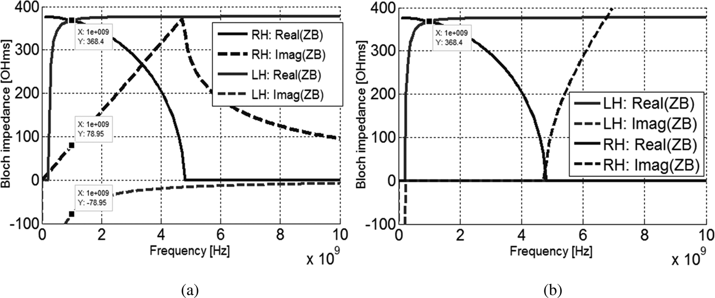
Yet, the Bloch impedances of symmetric RH/LH unit cells are purely real in the band pass delimited by the lower and upper cut-off frequencies of the LH and RH unit cells, respectively, as shown in Fig. 11. As a consequence, the propagating wave will not be attenuated after the ZIM region, as proved by the spatial variation of voltage shown in Fig. 12(b).
Variation of the constant of propagation according to the frequency: (a) for asymmetric RH/LH unit cells and (b) for symmetric RH/LH unit cells.
Voltage distribution along the transmission line using WCIP method (the same curves were obtained by an ADS simulator): (a) a purely RH transmission line; (b) the ZIM region (delimited by dashed lines) implemented by symmetric RH/LH unit cells; and (c) the ZIM region implemented by asymmetric RH/LH unit cells.

At 1 GHz, the RH/LH unit cells have insertion phases of 24 and −24°, respectively. The opposite insertion phases introduced by RH/LH unit cells can be clearly observed in the asymmetric case by the small undulations of the voltage through the ZIM region, as shown in Fig. 12(c).
The use of symmetric RH/LH unit cells to implement ZIM allows having an impedance matching between the various parts (Air, ZIM) of the analyzed circuits. Thus, we must have an electromagnetic wave propagation without attenuation after the ZIM region as shown in Fig. 12(b). Otherwise, with asymmetric RH/LH unit cells, we cannot maintain the matching condition. Therefore, an attenuation of the electromagnetic wave will be seen as shown in Fig. 12(c). In the case of ZIM-based asymmetric RH/LH unit cells, the voltage is measured at RH/LH unit cell's nodes alternatively. So, small undulations will happen on the ZIM region. But, when we have only one type of cell called CRLH unit cell, the insertion phase will be zero at each node and no undulations will be seen in this case.
In the following applications, we use symmetric unit cells to synthesize the ZIM medium, because we can match between the different cells since the characteristic impedance is purely real. After the theoretical explanation of the behavior of ZIM and how we use lumped element loaded microstrip transmission lines to generate them, we will illustrate the whole study by some applications highlighting the effectiveness of the WCIP method and the interest of the transmission line approach to synthesis ZIM. The next study will be based primarily on making interpretations starting from spatial distributions of voltage over the different circuits.
Applications
In all the following applications, we will consider an air filled medium matched with the ZIM medium. Thus, the calculated values of the lumped elements capacitors and inductors, at 1 GHz, are as the following: (C R = 88.5 fF, L R = 12.5 nH, C L = 2.0 pF, L L = 286 nH).
Behavior of waveguides partially loaded with zero-index materials
Figure 13(a) shows a 2-D waveguide loaded with ZIM. The excitation is done on the left by a line of sources. The waveguide is charged by a line of adapted impedances.
(a) Schematic of a rectangular waveguide loaded with ZIM, (b) the voltage distribution using WCIP method, and (c) the electric field distribution using COMSOL Multiphysics.

From Fig. 13(b), we can clearly see that there is no variation of the magnitude of voltage through the ZIM region. A total transmission and super-reflection of electromagnetic waves can be obtained by coating a region embedded in the ZIM medium by perfect magnetic conductor (PMC) or perfect electric conductor (PEC) boundary, as shown in Figs 14(a) and 14(d). Since we have manipulated periodic lumped circuits, the PMC and PEC boundaries are satisfied by doing open and short circuit boundaries, respectively. From Fig. 14(b), we can observe that the incident electromagnetic waves can pass the PMC-coated object which is located inside the ZIM region without reflection (total transmission). The same result was obtained using COMSOL Multiphysics software as shown in Fig. 14(c). However, when the object is coated by the PEC boundary, a super-reflection of the incident plane wave is observed, as depicted by the simulation results shown in Figs 14(e) and 14 (f) and obtained with WCIP method and COMSOL Multiphysics software, respectively.
(a) A waveguide which contains an air part coated with PMC boundary and its corresponding voltage distribution using WCIP method (b) and COMSOL Multiphysics (c); (d) a waveguide which contains an air part coated with PEC boundary and its corresponding voltage distribution using WCIP method (e) and COMSOL Multiphysics (f).

Effect of 2-D circular ZIM medium on the radiation of two embedded sources
First, two identical sources Sr1 and Sr2 are placed in free space, as shown in Fig. 15(a). We can detect from their radiation pattern a heterogeneous field distribution, which illustrates the interference phenomenon. The interference is constructive in a given position when the two emitted waves are in phase. However, the interference is destructive when the waves have phases with opposite signs. Second, the two sources are embedded in a circular ZIM region placed in free space as depicted in Fig. 15(b). We can clearly see a homogenous field distribution because all radiations exit the ZIM region with the same phase since there is no phase variation inside the metamaterial region.
(a) Two sources placed in free space and their corresponding spatial voltage distribution using WCIP method and (b) the two sources are embedded in a circular ZIM region.

To notice that all axes of voltage distribution are labeled according to the cell number. The right vertical scales designate the unit voltage.
Design of multi-beam antennas
If an electromagnetic source is placed inside a polygonal ZIM region embedded in a conventional dielectric medium, it will radiate into a number of directional beams equal to the number of sides of the peripheral boundary of the ZIM region [Reference He, Zhong, Zhou, Zhong and Dong7].
Figure 16 shows the cases of triangular, square and hexagonal ZIM regions. We see that the electromagnetic source radiates into three, four, and six directional beams respectively. Thus, we can have a multi-beam antenna by choosing a polygonal peripheral ZIM layer.
Voltage distribution through the ZIM-based antennas with free-space using WCIP method: (a) triangular-shaped antenna, (b) square-shaped antenna, and (c) hexagonal-shaped antenna.

Since the wavelength of the electromagnetic waves over ZIM media tends to infinity, many arbitrary embedded sources which initially have the same phase should interfere perfectly at all points in free space outside the ZIM region. We can use this characteristic to enhance the intensity of the electromagnetic field without perturbing the radiation pattern. This provides an interesting means to design antennas with enhanced far field radiation. Figures 17(a) and 17(b) show the voltage distribution through a ZIM square antenna, containing four sources.
Voltage distribution using WCIP method: (a) real (Ez) in volts, (b) abs (Ez) in volts, and (c) perfect combination of the sources’ radiations outside the ZIM region.

When the electromagnetic waves exit the ZIM metamaterial region, they radiate in the form of plane waves from the surrounding space to the far-field space. In Fig. 17(c), we can clearly observe that the sources’ radiations are perfectly combined outside the ZIM region. We can conclude that the use of ZIM permits to exhibit a perfect interference between many arbitrary located embedded sources without satisfying any particular interference condition.
Combination of the radiations of many sources embedded in ZIM on one focal point
Figure 18(a) shows an example of three point-sources located in arbitrary positions in the ZIM region. The frequencies of the three sources are the same in our simulations. The number of point sources in the ZIM region can be arbitrarily for both positions and numbers. The focuser region can be with an arbitrary outer boundary.
(a) Simulating model of the electromagnetic focuser with square shaped inner boundary; (b) 3-D view of abs (Ez) through the focuser and (c) top view of abs (Ez) using WCIP method; and (d) focalization of the radiations of the sources on the center of the square focuser.

From Fig. 18(c), we observe five focal points in the free space inner region of the focuser. Figure 18(d) shows that we can obtain a high voltage focal point at the center of the focuser by the addition of more sources inside the ZIM region. If the inner boundary of the focuser is circular, we will have a combination of all radiations in one focal spot at the center of the focuser. In fact, according to Snell's law, we can write the following equation:
 $$n_{ZIM}\sin \theta _{ZIM} = n_{AIR}\sin \theta _{AIR}\,\,\,$$
According to (21), if the ZIM refractive index n ZIM = 0 and the air refractive index n AIR ≠ 0, then sin θ AIR should be zero, which gives an angle of refraction equal to zero in free space. In other words, when the radiation of a given source is incident on the interface between the ZIM and free space, the refractive angle should be zero. Therefore, for a circular inner boundary focuser, all radiations exiting the ZIM region to the free space region should be focused on one focal point at the center of the focuser as shown in Fig. 19.
(a) 3D-view and (b) top view of Abs (Ez) through the electromagnetic focuser with circular-shaped inner boundary using the WCIP method.

A black circle is added in Fig. 19(b) to show the inner boundary of the circular focuser. ZIM can be used to exhibit a perfectly constructive interference independently of the locations of the embedded point sources. The above simulation results are convenient with the literature results depicted in [Reference Zhai, Shi, Chen, Liu and Zhang32].
Conclusion
In this paper, we have demonstrated how to use lumped element loaded transmission lines to synthesize ZIM. Then, we have illustrated the whole theoretical study by applications highlighting the importance of ZIM, such as the design of multi-beam antennas, the perfect combination of many sources’ radiations without any particular condition, and the transmission and the super reflection of electromagnetic waves inside waveguides partially loaded with ZIM. All simulations are carried out using an advantageous WCIP method suitable for this kind of electromagnetic problems.
 Mohamed Karim Azizi was born in Tunis, Tunisia, on December 26, 1979. He received his M.Sc. degree in Telecommunications from SupCom in 2008. He received his Ph.D. degree in Electronics from the Faculty of Sciences of Tunis, Tunisia in 2013. He is currently an associated Professor in the Department of Computer Sciences in The Higher Institute of Multimedia Arts of Mannouba, ISAMM, Tunisia. His research interest at present includes metamaterials, metasurfaces, and graphene antennas.
 Taieb Elbellili was born in Kasserine, Tunisia, on April 29, 1980. He received his M.Sc. degree in Electronic systems from the Faculty of Sciences of Tunis, Tunisia in 2006. Since 2015, he has been working toward his Ph.D. His research focuses on computational electromagnetic methods for metamaterial modeling.
 Henri Baudrand (SM'90–F'04–LF'14) received his Ph.D. degree in microwaves from the Institut National Polytechnique, Toulouse, France, in 1966. He is a Professor Emeritus with the Ecole Supérieure d'Electronique Electrotechnique Informatique, ENSEEIHT, National Polytechnic Institute of Toulouse, Toulouse, France. He has authored and coauthored six books: Introduction au calcul des éléments de circuits microondes, optimisation des circuits non linéaires, calcul des circuits microondes par les schémas équivalents (CEPADUES Editions Toulouse), New Trends and Concept in Microwave Theory and Technics, Adaptation de la méthode WCIP aux circuits SIW et SINRD: WCIP: Wave Concept Iterative Process, and Modélisation Globale des Circuits Electroniques Hautes Fréquences. He cosigned over 110 publications in journals, four chapters in scientific books, and 250 communications in international conferences. He is a Fellow Member of “Electromagnetism Academy” and Senior Member of IEE Society. He was President of URSI France Commission B for 6 years (1993–1999), the IEEE-MTT-ED French chapter (1996–1998), and the International Comity of O.H.D. (Hertzian Optics and Dielectrics) between 2000 and 2004. He was the recipient of Officier des Palmes académiques and Doctor Honoris causa of lasi University (1996).
 Hichem Trabelsi was born in Tunisia, in 1962. He received his Ph.D. in Electronics from the University of Pierre & Marie Curie, Paris VI, France in 1991. He joined the Department of Physics at the Faculty of Sciences, Tunis, in 1992, where he is currently working on microwave active and passive filters and electromagnetic theory for solving field problems in microwave circuits.



