1. INTRODUCTION
To reach the intensity goals of the FAIR project, intermediate charge state heavy ions, that is, U28+ will be accelerated. These ions suffer from high cross-sections for charge exchange at collisions with residual gas molecules. Due to the difference in magnetic rigidity, stripped ions are lost downstream at positions with high dispersion. The impact of these ions stimulates a local pressure bump. Consequently, the probability for further charge exchange is enhanced. Above a critical beam intensity a self-amplification with significant beam loss may develop. This self-amplification can be damped by several measures, for example, the installation of high pumping power and low desorbing surfaces at the positions of impact.
2. ION CATCHER SYSTEM IN SIS100
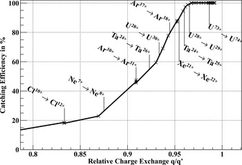
The ion optical layout of the superconducting synchrotron SIS100 has been optimized to generate a peaked loss distribution for ionized beam particles. Such a peaked loss distribution allows the implementation of an effective ion catcher system (Spiller et al., Reference Spiller, Blasche, Franczak, Stadlmann and Omet2004; Stadlmann et al., Reference Stadlmann, Blasche, Franczak, Omet, Pyka, Spiller and Kovalenko2006). Stripped beam ions are lost at well-defined, highly localized positions in the cryogenic arcs. The peaked loss distribution enables a stabilization of the amount of charge exchange processes. For the reference ion with the most probable charge exchange process U28+ → U29+, a catching efficiency above 99% is reached (see Fig. 1). The relative charge exchange q/q′ is the ratio of the ion's charge state before q and after q′ the charge exchange process. It determines the difference in deflection angles in the dipole magnets, the ionization loss distributions, and the catching efficiencies. This parameter does not depend on the beam energy. However, the catching efficiency benefits from the shrinking emittance during acceleration. Since the ionization cross-sections decrease with the atomic number, lower catching efficiencies and stronger vacuum dynamics do not generate enhanced beam loss during operation with lighter ions.
Catching efficiency of the SIS100 ion catcher system. Single ionization of heavy ions results in a small relative charge exchange q/q′.For example, for single ionization of the reference ion U28+ → U29+, almost 100% of the lost ions are controlled (Bozyk et al., Reference Bozyk, Hoffmann, Spiller and Kollmus2010).

A complete overview of the ion catcher system in SIS100, including the design of the cryocatcher, test setup, test procedures, and results can be found in (Bozyk, Reference Bozyk2012).
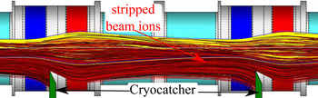
Figure 2 shows the working principle of the ion catcher system in SIS100: In dispersive elements (dipoles), ions with changed charge state are separated from the circulating beam. Due to their displacement from the design orbit and due to the defocussing of the first quadrupole, these ions hit the ion catcher which is situated in the middle of the quadrupole doublet.
In dispersive elements (dipoles, cyan), ions with changed charge states (red lines) are separated from the circulating beam (yellow). The charge separator lattice of SIS100 enhances the displacement from the design orbit. After the defocussing of the first quadrupole (blue), such ions are lost on the ion catcher.

In the existing normal conducting synchrotron SIS18, a room temperature ion catcher system (Omet, Reference Omet2009) has been installed. The ion catcher system is one of the upgrade measures for the planned booster operation and helps to stabilize the residual gas pressure at operation with high intensity U28+-beams. In contrary to SIS100, in SIS18 ion catchers are installed on both sides of the beam axis. The current on all ion catchers can be measured. Current measurements are also foreseen for the SIS100 cryocatchers. The catcher current scales with ionization losses and with the strength of the residual gas pressure dynamics upstream the ion catcher. The current measurement with the SIS18 catcher system has been used for systematic studies on ionization and capture loss processes (Bozyk & Spiller, Reference Bozyk and Spiller2014).
Electron capture processes are most pronounced at injection energy of SIS18. During the acceleration process, the cross-sections for electron capture drop several orders of magnitude below the cross-sections for electron loss. Therefore, in SIS100, ion catchers will only be installed on the inner side of the ring (Bozyk et al., Reference Bozyk, Hoffmann, Spiller and Kollmus2010).
3. ENGINEERING DESIGN OF THE SIS100 CRYOCATCHER
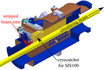
Since the ion catchers will be installed in the superconducting quadrupole doublets, their design has to be suitable for a cryogenic environment. The design of a single cryocatcher, including its surrounding chamber, is sketched in Figure 3.
Sketch of the cryocatcher prototype (orange): Vacuum chamber in blue, surrounding copper coating in brown, circulating beam in yellow, trajectories of ionized beam ions in red, desorbed gases as colored balls, cold surfaces (secondary chamber plates) in brown.

To avoid freeze-out of gas molecules on the surface of beam impact, the cryocatcher itself is stabilized at a higher temperature than the surrounding vacuum chamber. Thereby, its molecular surface occupancy and consequently the desorption yields remain low. To minimize the heat load onto the cooling system, the cryocatcher support is designed as a cold–warm transition. It contains a bellow which provides a high thermal resistance and separates the beam vacuum from the insulation vacuum (Bozyk et al., Reference Bozyk, Hoffmann, Spiller, Kollmus and Wengenroth2011).
The actual support of the cryocatcher consists of a copper block inside this bellow. The block provides a good thermal contact to the warmer side of the bellow. In this way, a thermal connection between the ion catcher and the insulation vacuum is established. The thermal contact is used to connect the cryocatcher to the thermal shield cooling. Thus, the energy deposited by lost ions is dissipated via the shield cooling instead of the chamber cooling and the cryocatcher is stabilized at a higher temperature than the surrounding vacuum chamber (Bozyk et al., Reference Bozyk, Hoffmann, Spiller, Kollmus and Wengenroth2011).
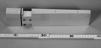
The cryocatcher consists of a 25 cm long copper block. The length was optimized by FLUKA-simulations (Ferrari et al., Reference Ferrari, Sala, Fassò and Ranft2005; Bozyk et al., Reference Bozyk, Hoffmann, Spiller and Kollmus2010, Bohlen et al., Reference Bohlen, Böhlen, Cerutti, Chin, Fassò, Ferrari, Ortega, Mairani Sala, Smirnov and Vlachoudis2014). The front part is electrically insulated from the rear part, such that the electrical current of ions hitting the cryocatcher can be measured. The copper catcher has a nickel–gold coating, which provides low desorption yields at room temperature (Bender, Reference Bender2008). Two different geometries have been tested in the prototype: a block catcher, as shown in Figure 3, similar to the approved catchers in SIS18, and a stair-like catcher, which provides perpendicular incidence and a shielding of the desorbed molecules from the circulating beam. The distance of the ion catcher from the beam axis (35 mm) is chosen such that the accelerator acceptance is not affected, while the catching efficiency is as high as possible (Bozyk et al., Reference Bozyk, Hoffmann, Spiller, Kollmus and Wengenroth2011). A photograph of the cryocatcher with block geometry is shown in Figure 4.
Photograph of the gold plated SIS100 cryocatcher block: The front part (left) is electrically insulated from the back part (right) by a ceramic spacer (not shown). Ions hit the cryocatcher from the left side.

The cryocatcher is embedded in shielding walls made of copper plates. This cold shielding reduces the vacuum conductance toward the beam axis and provides additional cold surfaces for pumping. To minimize the rise of the residual gas density during ion bombardment, the vacuum chamber around the cryocatcher has been increased relative to the beam pipe. The geometry of the secondary chamber, the distance of the front side of the cryocatcher from the chamber wall, and the increased aperture were optimized by means of Molflow (Kersevan & Pons, Reference Kersevan and Pons2009). Thus, the pressure rise on the beam axis could be significantly reduced (Bozyk et al., Reference Bozyk, Hoffmann, Spiller, Kollmus and Wengenroth2011).
The chamber surrounding the cryocatcher acts as a cryopump and provides high pumping power. To assure a uniform temperature distribution, the chamber, which is made of stainless steel, is coated with copper on the outer side. The coating has been explosively plated onto the stainless steel before the chamber was manufactured. Several tests have been performed to assure the cryosuitability of this coating technique. The chamber is connected to a helium supply line via flexible copper straps (Bozyk et al., Reference Bozyk, Hoffmann, Spiller, Kollmus and Wengenroth2011).
In SIS100, the cryocatcher will be installed between two quadrupole magnets, inside the quadrupole cryostat. Ten catchers are foreseen in each arc (60 in total). The vacuum chamber of the cryocatcher will also be used to evacuate the beam pipe before cooling-down the machine. This design assures that the initial areal density of frozen gases on the cryocatcher is minimized. The ultra-high vacuum (UHV)-pumping port will be attached in the rear part of the vacuum chamber.
4. PROTOTYPE TEST SETUP
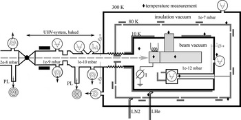
To verify the models for temperature and pumping, as well as to investigate the desorption behavior of the cold cryocatcher, a prototype cryocatcher has been built. Figure 5 shows a sketch of the prototype setup (Bozyk et al., Reference Bozyk, Spiller and Kollmus2012).
Sketch of the cryocatcher prototype test setup. The beam hitting the cryocatcher is indicated as long dashed arrow (Bozyk et al., Reference Bozyk, Spiller and Kollmus2012).

The chamber with the cryocatcher inside is connected to a LHe pipe. The chamber is surrounded by a LN2-cooled thermal shield inside the cryostat vessel. A cold–warm transition connects the cryocatcher chamber to the warm beam pipe. Different to the situation in SIS100, the prototype is directly irradiated by the primary beam from SIS18.
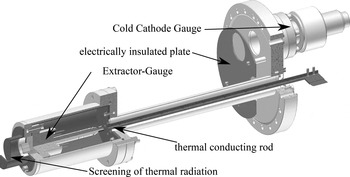
During the tests the pressure rise generated by desorbed molecules has been investigated. The pressure was measured by a cold penning gauge, which was mounted on the backside of the chamber and a thermally shielded hot extractor gauge, which was mounted on a long pipe sticking into the chamber (see Fig. 6). The latter allows pressure measurements close to the cryocatcher head surface. In front of the cold–warm transition, in the warm beam pipe section, a further extractor gauge and a residual gas analyzer were installed (Bozyk et al., Reference Bozyk, Hoffmann, Spiller, Kollmus and Wengenroth2011).
Pressure measurement inside the cold cryocatcher chamber: The hot extractor gauge is situated close to the cryocatcher. To dissipate the heat, the gauge is thermally connected to the radiation shield. On the backside of the chamber, a cold cathode gauge is installed. An electrically insulated plate is used to detect beam, which missed the cryocatcher.

A scintillator screen situated in the same chamber was used to adjust the beam position. For further control of the beam position during the tests, several electrically insulated plates have been mounted around the cryocatcher. The electrical currents onto these plates had to be minimized, whereas the current on the cryocatcher had to be maximal. One of these plates is shown in Figure 6 (Bozyk et al., Reference Bozyk, Hoffmann, Spiller, Kollmus and Wengenroth2011).
Since a residual gas pressure of P < 10−11 mbar was predicted for the inside of the cold chamber, a differential and bakeable pumping system with a small vacuum conductance was installed in front of the setup. Part of the differential pumping system is a resonant beam transformer, which allowed us to measure the particle currents. Upstream the pumping line, a further scintillator screen was installed to assure a parallel incoming beam. A full metal valve allowed us to separate the accelerator vacuum from the test setup.
To control the cooling, to verify temperature models, and to obtain reference temperatures for pressure measurements, temperature sensors were mounted on different components like the LHe-pipe, cold chamber, vacuum gauges, the cryocatcher, and its mounting.
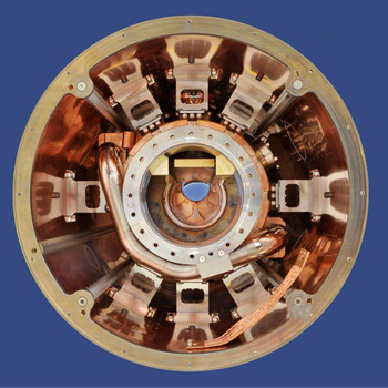
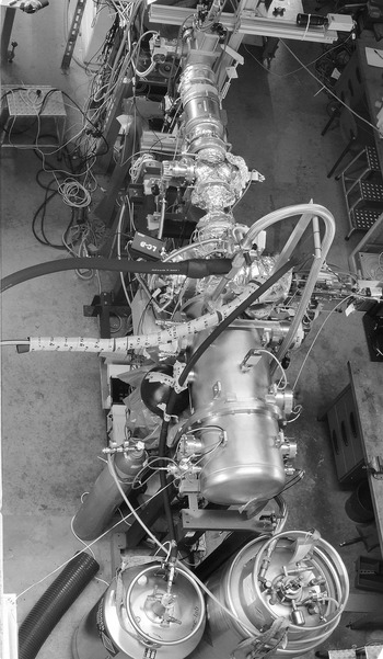
Figure 7 shows a photograph of the assembled prototype cryocatcher inside the thermal shield. The fully assembled setup in the cave, ready for beam tests, is shown in Figure 8.
Photograph of the assembled cryocatcher prototype from the backside: The cryocatcher itself (gold) is surrounded by an explosively plated UHV-chamber, which is aligned inside the thermal shield of the test-cryostat (Picture by G. Otto, GSI).

Photograph of the whole test setup installed in the experimental cave, ready for operation (Picture by G. Otto, GSI).

5. TESTS AND DESORPTION MEASUREMENT
For the experiments with ion beams, the cryocatcher prototype was cooled with liquid nitrogen and liquid helium. On the inner chamber, temperatures down to 10 K could be reached. A transition temperature of ~18 K, underneath a strong pumping of hydrogen emerges, could be verified several times. Each time a lower temperature has been reached, the pressure dropped within minutes by two orders of magnitude down to 10−12 mbar within several minutes. Exceeding the temperature results in a fast pressure rise by several orders of magnitude, and all adsorbed gases on the surface are released quickly (Bozyk et al., Reference Bozyk, Hoffmann, Spiller, Kollmus and Wengenroth2011).
Several beamtimes have been conducted to investigate the heavy-ion impact induced desorption yields at the cryocatcher. The block geometry was tested with gold and tantalum (Ta) beams at energies between 50 and 800 MeV. During the Ta-beamtime, measurements at room temperature have been performed. The stair-like catcher was tested with Bismuth ions at beam energies between 100 and 600 MeV. Only fast extracted beams were used, with intensities of up to 2 × 10⁹ ions per shot. For selected energies, the cryocatcher's temperature was varied between 35 and 90 K (Bozyk et al., Reference Bozyk, Hoffmann, Spiller, Kollmus and Wengenroth2011).
The cryocatcher and its support showed a quite homogeneous temperature. Fast beam-induced temperature changes on the cryocatcher-head were distributed quickly along the whole cryocatcher. The temperature of the support, measured from the insulation-vacuum side, differs only slightly from the cryocatcher's head, that is, the deposited energy can be dissipated effectively. The temperature of the cryocatcher could be varied by 40 K, while the temperature of the vacuum chamber only changed by <2 K. The support of the cryocatcher provides a high thermal resistance and thus fulfills its requirements (Bozyk et al., Reference Bozyk, Spiller and Kollmus2012).
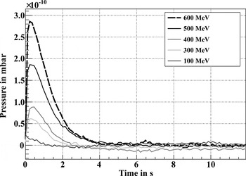
The ion current of the extractor gauge situated next to the cryocatcher head was measured with an external ampere meter. Thereby, a fast pressure measurement, triggered by the incoming beam, could be realized. Figure 9 shows exemplarily some pressure developments for different impact energies.
Pressure evolution after the impact of Bi ions onto the cryocatcher (Bozyk et al., Reference Bozyk, Hoffmann, Spiller, Kollmus and Wengenroth2011).

The difference between peak and relaxation pressure gives the ion induced pressure rise Δp. Using the number of incident particles N Ion, the gas temperature which is equivalent to the chamber temperature T, and the chamber volume V, the desorption yield η is calculated:
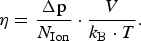 $${\rm \eta} = \displaystyle{{\rm \Delta p} \over {N_{{\rm Ion}}}} \cdot \displaystyle{V \over {k_{\rm B} \cdot T}}.$$
6. RESULTS
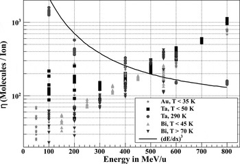
During the different beamtimes with gold, Ta, and bismuth, the desorption yield η was investigated as a function of ion energy and cryocatcher temperature. The measured yields are summarized in Figure 10. From room temperature measurements a scaling of the desorption yield with the electronic stopping power to the third power is known (Molvik et al., Reference Molvik, Kollmus, Mahner, Kireeff Covo, Bellachioma, Bender, Bieniosek, Hedlund, Krämer, Kwan, Malyshev, Prost, Seidl, Westenskow and Westerberg2007; Kollmus et al., Reference Kollmus, Krämer, Bender, Bellachioma, Reich-Sprenger, Mahner, Hedlund, Westerberg, Malyshev, Leandersson and Edqvist2009). This behavior could be reproduced using the cryocatcher test setup at room temperature, whereas at cryogenic temperatures a contrary scaling was observed: The desorption yield increases with increasing energy. In the investigated energy and temperature interval (30–90 K) this scaling shows no dependence on the temperature of the cryocatcher. Crossing the vapor pressure curve of CO2 about 63 K without any reaction of η shows, that no cryocondensation, but only cryoadsorption at higher temperatures takes place on the cryocatcher. During the bismuth beamtime the stair-like cryocatcher was used, but no significant screening of desorbed gases, that is, no different scaling of the desorption yield, could be observed.
Desorption yields measured at the cryocatcher during different beamtimes (Bozyk et al., Reference Bozyk, Spiller and Kollmus2012).

The slow pressure decay after beam impact was used to estimate pumping speeds. A qualitative saturation of the cold surfaces could be observed. Immediately after falling below the transition temperature, the highest pumping speed could be measured. The pumping power decreases with time, as gases from the warm sections flow into the cold chamber, saturating the surfaces. With fully saturated surfaces, the pumping power adopts the same value as with temperatures above 20 K. Dedicated measurements are planned to investigate the hydrogen pumping and its saturation (Bozyk et al., Reference Bozyk, Spiller and Kollmus2012).
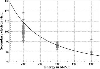
The measured electrical current on the cryocatcher head was used to calculate the secondary electron yields plotted in Figure 11. It scales with the electronic energy loss as expected from (Rothard et al., Reference Rothard, Kroneberger, Clouvas, Veje, Lorenzen, Keller, Kemmler, Meckbach and Groeneveld1990). However, the magnitude is reduced by a factor 5, which may be explained by a reduced electron mobility in a cryogenic target compared with room temperature measurements in (Rothard et al., Reference Rothard, Kroneberger, Clouvas, Veje, Lorenzen, Keller, Kemmler, Meckbach and Groeneveld1990), or by transmission losses to the readout electronics (Bozyk et al., Reference Bozyk, Spiller and Kollmus2012).
Secondary electron yields measured at the cryocatcher during gold-beamtime compared with the electronic stopping power on the surface in arbitrary units (Bozyk et al., Reference Bozyk, Spiller and Kollmus2012).

To use the measured desorption yields, the data in Figure 10 are described by the following parabola:
 $${\rm \eta} (E) = 1.27 \times 10^{ - 3} \cdot E^2 - 0.15 \cdot E + 50.$$
Here E is the energy in MeV/u (Bozyk, Reference Bozyk2012; Bozyk et al., Reference Bozyk, Spiller and Kollmus2012). This parametrization and its extrapolation to the SIS100-top-energy, has been implemented in the StrahlSim code (Puppel, Reference Puppel2012). The increasing desorption yields are compensated by decreasing charge exchange cross-sections during acceleration. This results in a stable operation with intensities of 5 × 10¹¹ U28+ particles per cycle (Bozyk et al., Reference Bozyk, Spiller and Kollmus2012).
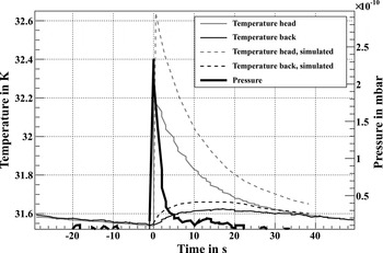
The temperature and pressure evolution during the impact of 1.12 × 10⁹ Ta-ions with an energy of 800 MeV/u onto the cryocatcher is shown in Figure 12. Both show a fast, beam induced rise, followed by a slow decay. Due to its thermal conductance and capacity, the temperature of the backside of the cryocatcher follows with a damped delay. The temperature of the support also responds delayed with respect to the beam impacts. The thermal reaction of the cryocatcher can be well reproduced by ANSYS simulations. In the simulations, the temperature on the surfaces of the cryocatcher was calculated. The small difference of <400 mK between measured and simulated evolution is due to the neglected thermal capacity and conductance of the temperature sensors. The thermal conductivity of the different connections and junctions of the cryocatcher were estimated for the simulations and the thermal stability of the cryocatcher for different loss scenarios in SIS100 was verified (Bozyk, Reference Bozyk2012; Bozyk et al., Reference Bozyk, Spiller and Kollmus2012).
Pressure and temperature evolution in the cryocatcher. The thermal reaction can be reproduced with ANSYS-simulations (Bozyk et al., Reference Bozyk, Spiller and Kollmus2012)

7. IMPLICATIONS FOR THE SIS100 CRYOCATCHER SYSTEM
Since the tests and measurements have proven the desired functionality, the SIS100 series cryocatcher has been specified and constructed based on the design of the prototype. Nevertheless, the measurements have some implications for the SIS100 cryocatcher. To have a sufficient pumping power, it is important to keep the chamber temperature below the transition temperature of 18 K. The gas flow into the cold sections has to be kept low, in order to preserve the pumping power. Therefore the room temperature parts of the pumping posts should be equipped with additional hydrogen pumps, for example, non-evaporable getter (NEG) cartridges. Since beam impacts were noticeable at the temperature measurements on the support of the cryocatcher, a temperature sensor must not necessarily be mounted on the cryocatcher itself. To assure that during cooldown the cryocatcher remains warmer than its surrounding vacuum chamber, the temperature of the cryocatcher can be adjusted by a heater element mounted on the support. This is necessary to keep the initial surface adsorbates low (Bozyk et al., Reference Bozyk, Spiller and Kollmus2012).
The temperature of the thermal shield of SIS100, where the cryocatcher will be thermally connected to, is expected to vary between 50 and 80 K along one arc. Since in the investigated temperature interval, the desorption yield is independent from the temperature of the cryocatcher, this represents no issue. Regardless from this fact, the connection to the thermal shield has to remove the deposited energy of the lost ions (Puppel et al., Reference Puppel, Spiller and Ratzinger2011) reliable. Simulations have confirmed the thermal stability of the cryocatcher for high beam loss scenarios (Bozyk, Reference Bozyk2012; Bozyk et al., Reference Bozyk, Spiller and Kollmus2012).
The thermal simulations have also indicated, that by choosing a different material for the head of the cryocatcher, the desorption yield could be further reduced. By changing the temperature of the cryocatcher from room temperature to cryogenic temperatures, its thermal capacity drops, while its conductivity rises. Such, the energy deposited by the beam ions, which is absorbed deep inside the material, propagates more efficient to the surfaces, where desorption is triggered. Planned dedicated measurements on cryogenic desorption will show, if an optimized material can be found (Bozyk et al., Reference Bozyk, Spiller and Kollmus2012).
According to this consideration, the screening effect of the stair-like cryocatcher is compensated by its bigger surface. Since no visible dependence of the beam energy could be observed, a calibration of the electrical current measurement is not trivial. Additionally the manufacturing is more demanding for which reason the simple block geometry has been preferred (Bozyk et al., Reference Bozyk, Spiller and Kollmus2012).
The length of the head of the cryocatcher is chosen such that lost beam ions are completely stopped inside. This divides the cryocatcher into a high and a low activated part. After the beamtime only slight activation of the backside could be measured. The activation of the front part is mainly determined by cobalt isotopes, with a maximum half-life of 5.2 years (Bozyk et al., Reference Bozyk, Spiller and Kollmus2012).
8. SUMMARY
A cryocatcher for SIS100 has been designed and a prototype including dedicated test cryostat has been constructed and manufactured. Several tests have been performed with liquid helium, liquid nitrogen cooling, and heavy-ion beam bombardment from SIS18 at GSI. Residual gas pressures in the low 10−12 mbar regime were reached. The transition temperature of 18 K underneath a high pumping power for hydrogen emerges, could be verified. Exceeding this temperature resulted in fast pressure rises by several orders of magnitude.
The effective desorption yields of the cryocatcher prototype were investigated. An unexpected energy scaling was observed for the first time: the desorption yield increases with increasing energy. From room temperature measurements a scaling with the electronic energy loss on the surface, that is, a decrease with increasing energy is known. This scaling was reproduced with the cryocatcher test setup at room temperature.
The thermal response of the cryocatcher can be reconstructed in simulations and its thermal stability for predicted loss scenarios in SIS100 could be verified. Dynamic vacuum simulations using the measured desorption yields predict a stable operation at high intensities.
The cryocatcher fulfills its requirements and assures that no vacuum instabilities and self-amplifying ionization losses occur in SIS100. The series cryocatcher for SIS100 is specified on the basis of the prototype.
ACKNOWLEDGMENTS
The authors would like to thank all the people, who helped during design, construction, installation of the test setup, and measuring. The tests were an exemplary GSI-wide collaboration between many departments.