Introduction
Nowadays wearable technology is a developing area based on energy harvesting. It is used to power the integrated devices into clothing like sensors, LED displays, and to charge the super capacitors etc. Mostly the energy can be harvested from solar, piezoelectric, microwave energy sources to power low, ultra-low power electronics, sensors or to recharge thin super capacitors. Researchers are inventing new technologies and materials which have less weight and flexible to wear and it can integrate into clothing. Especially, the flexible solar cell has more potential applications in the real-time energy harvesting applications because they are light in weight, thin, flexible, and easy to integrate with clothes. Thus, the energy harvesting system has been reported using polyamide thin film photovoltaic smart bracelet for healthcare application, measuring the heartbeats of a patient through photoplethysmography (PPG) [Reference Jokic and Magno1, Reference Wu, Arefin, Redouté and Yuce2]. Inductively, the power transfer circuit is designed on plastic with the flexible solar cell as a power source [Reference Hu, Rieutort-Louis, Huang, Sanz-Robinson, Wagner, Sturm and Verma3], an intelligent hardware-based charging controller circuit is presented for wireless sensor application [Reference Li and AU-Shi4].
The concept of solar cell antenna is the integration of solar cell and microwave antenna, therefore it becomes a hybrid energy harvesting system. There are several methods to achieve this. At first rigid solar cell integration are reported here, in [Reference Tanaka, Suzuki, Araki and Susuki5], an antenna is superimposed on silicon solar cell with separation gap of 5.5 mm, direct stimulation of GaAs solar cell and monocrystalline Si (mono-Si) solar cell is detailed in [Reference Vaccaro, Mosig and de Maagt6, Reference Henze, Giere, Fruchting and Hofmann7]; In [Reference Nair, Roo Ons, Ammann, McCormack and Norton8] a shorted patch over solar cell is reported. The integration methods that are reported above are the effected electrical output of the rigid solar cell due to the shadow of the integrated antenna.
Several researchers have reported a flexible solar cell integrated antenna. An amorphous-Silicon (a-Si) grown directly on the ground plane of a 4.1 GHz stainless steel slot antenna in [Reference Vaccaro, Torres, Mosig, Shah, Zürcher, Skrivervik, de Maagt and Gerlach9], a low cost compact solar/electromagnetic harvester designed on flexible polyester in [Reference Andia Vera, Georgiadis, Collado and Via10], dual band rectenna made of flexible Polyethylene Terephthalate (PET) substrate in [Reference Collado and Georgiadis11], multi-input multi-output three source solar, vibration and thermal harvester in [Reference Sun, Guo, He and Zhong12], and vibration-based micro-electrometrical energy harvester in [Reference Song, Houng, Zhou, Zhang, Yuan and Carter13, Reference Bandyopadhyay and Chandrakasan14]. In the research work reported above, the solar cell is not part of the radio frequency (RF) operation, which means antenna and solar cell are the two separate elements.
The conversion of ambient microwave power into direct current (DC) power has been done by a circuit called rectenna. Usually, rectenna consists of a RF receiving antenna and a rectifying circuit. Generally, three types of diode rectifier circuits are used in the rectification process, which are a diode [Reference Popovic15], a bridge of diode [Reference Ghovanloo and Najafi16], and a voltage rectifier multiplier [Reference Curty, Declercq, Dehollain and Joehl17]. The different matching and rectifier circuits for solar/electromagnetic energy harvesting are well discussed in [Reference Niotaki and Collado18], such as conventional coplanar waveguide (CPW) [Reference Niotaki, Giuppi, Georgiadis and Collado19], resistance compression network (RCN), and combination of both are reported in [Reference Yehui, Leitermann, Jackson, Rivas and Perreault20].
This paper reports, for the first time, a flexible and wearable photovoltaic cell fully integrated antenna system, which is designed to harvest both photovoltaic and microwave energies. The solar cell, rather than being used as a separate element (antenna will function without solar cell [Reference Tanaka, Suzuki, Araki and Susuki5–Reference Bandyopadhyay and Chandrakasan14]), it works as a part of the RF operation in addition to their photovoltaic function. A thin film amorphous solar cell encapsulation has multiple layers in it, these layers are used as substrate for the design of dual band rectangular loop antenna. The flexible solar antenna is coupled to the rectification circuit, which is designed on a jeans fabric. The complete system harvests microwave energies at 1.85 and 2.45 GHz bands with power level start from −15 dBm and solar energy from the surrounding environment.
Design of wearable antenna
The planar microstrip antenna is a low weight device. It is easy to design and fabrication. The wideband and multiband operation is obtained at low cost. The way, the microstrip antenna is incorporated with modern electronics for communication, in the same way, we can power the wearable electronics and sensors. There are two methods to integrate the antenna with a solar cell for energy harvesting. First one is autonomous integration of antenna with a solar cell, in which solar cell is a separate power source. The second one is the full integration of antenna with a solar cell, in which the antenna is designed upon the solar cell.
To power the wearable electronics, full integration technique is used in this work, which means microstrip antenna is integrated with thin film solar cell. The flexible solar cell is enclosed with flexible dielectric materials like ethylene-vinyl acetate (EVA), nylon polymer and ethylene tetrafluoroethylene (ETFE) in a stacked manner, thus these stacked multilayers are used as a substrate for the antenna design. The microstrip antenna integrated with a solar cell has the rectangle ring shape. The geometry of the proposed antenna is shown in Fig. 1. Firstly the rectangular patch with dimensions L 1 = 58 mm and W 1 = 198 mm is printed on the top surface of the solar cell and a rectangular cut with dimensions L 2 = 50 mm and W 2 = 88 mm to remove the portion of the rectangular patch is embedded. The dimension of the rectangular slot is the same as the stainless steel sheet on which amorphous silicon is coated, this stainless steel sheet is shown in Fig. 2(a). A partial ground plane with dimensions Lg = 22 mm, Wg = 188 mm is used in the antenna design; An inset feed technique is used to match the impedance of the rectangular ring with SMA connecter for better results and the physical dimensions of the rectangular ring antenna are presented in Table 1
Geometry of a rectangular loop microstrip antenna.

Multiple layers in the encapsulation of a solar cell.

Antenna parameters

Any microstrip antenna mainly requires three elements, radiating element, dielectric substrate, and ground plane; encapsulating materials are mostly dielectric materials and the radiating rectangular ring and ground plane is designed by a copper foil tape. Multilayers in the encapsulation are shown in Fig. 2(b), and the same is modeled in CST Microwave Studio as a six-layer structure as, Nylon-EVA-Nylon-EVA-ETFE, which is shown in Fig. 3 (Table 2).
Stacked layers in the encapsulation are designed in CST microwave environment.

Layers in the encapsulation

Microwave rectification
Analysis of voltage doubler
There are several types of topologies in the rectification of RF to DC such as single series, single shunt, full-wave diode rectifiers [Reference Marian, Allard, Vollaire and Verdier21], and voltage double rectifiers. The efficiency of the rectenna depends on frequency, RF diode type, input power level, matching between antenna and rectifier circuit; power losses if rectifier offers minimum losses electrical efficiency is high. Therefore standard voltage doubler is the noble option over half-wave rectifier at ultra-low power levels. Microwave signal arrived at the input of the rectifier vin = VAC Sinωt here VAC is the amplitude and ω is the frequency of the input signal.
Figure 4 explains the rectification of microwave positive and negative half cycle at voltage doubler. The diode D 1 comes into forward bias to negative half-wave and capacitor C 1 charges, the diode D 2 rectifies the positive half-wave, and capacitor C 2 is charged. Finding the input impedance of the RF (voltage doubler) diode for the design of matching circuit is the vital point since diode has non-linear characteristics. The output DC voltage (VDC) at the load is given by Eq. (1) and input impedance of the voltage doubler is calculated by using Eq. (2) [Reference Song, Huang, Carter, Zhou, Yuan, Xu and Kod22], where IS is the diode saturation current, m is the ideality factor, and VT is the thermal voltage.


Schematic of the voltage doubler circuit and its operation.

Large-signal S-parameter (LSSP) is a non-linear simulation that accounts for power level-dependent behavior of the diode. The LSSP simulation of the impedance circuits is carried out to measure the degree of matching between source and voltage doubler against microwave input power level.
The voltage doubler circuit, designed in ADS software is shown in Fig. 5, and the same is analyzed with LSSP simulation to verify the power level-dependent and non-linear characteristics behavior of the Schottky diode SMS7630 [23]. The input impedance of the voltage doubler (ZVD) obtained from ADS simulation is depicted in Fig. 6, at 1.85 GHz the impedance is ZVD = 43.071-j301.519 and 2.45 GHz it is ZVD = 28.963-j228.833 with −30 dBm as input power for a load resistance of 7.5 KΩ. It is clear that the real part of the voltage doubler is affected by the frequency, it changes from 43.071 to 28.963 Ω; the imaginary part effected more rapidly changes from 301.519 to 228.833 Ω.
Voltage doubler block designed in ADS software.

Simulated input impedance of the voltage doubler.

Dual band impedance matching
The primary goal of the matching circuit minimizes the reflection from the voltage doubler, maximizes the received microwave power, and matching is necessary for power transfer from one stage to another [Reference Pavone, Buonanno, D'Urso and Corte24–Reference Wang, Zhang, Xu, Bai, Liu and Shi27].
In the microwave frequency region, filters can be designed using distributed transmission lines. Series inductors and shunt capacitors can be realized with microstrip transmission lines.
There are different kinds of approaches which are used to design dual band filter such as filters operating for each frequency and adding them in parallel. Dual band stub is like a parallel open-shorted stub, simple Tee, Pi circuits, and steeped impedance matching. In case of dual band energy harvesting, rectifier has to be matched with the antenna at both the frequencies to increase the conversion efficiency. Thus, two individual filters are designed for each operating frequency and connected in parallel to match the impedance between the source and voltage doubler.
The microstrip line filter is designed with shunt open and series stubs technique by using smith chart utility in ADS and implemented on jeans textile dielectric substrate with a relative dielectric constant of 1.6 and thickness of 1 mm. The ADS model of the matching filter is shown in Fig. 7(a) and the simulated and measured return loss plot (S11) of the rectifier circuits is shown in Fig. 7(b) at two resonance frequencies. The matching circuit has the return loss coefficient of −20 dB at both resonance frequencies for a −5 dBm power level, for −10 dBm input power level the S11 magnitude is below −20 dB but slightly shifted from center frequencies but still within the band limits. The rectifier is well matched for input RF power levels from −20 to −5 dBm.
(a) Rectifier ADS model. (b) Measured and simulated S 11 plot for three different input power levels at 2.45 and 1.86 GHz.

Fabrication of rectifier
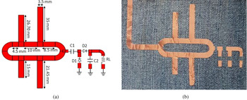
Voltage doubler long with matching circuit was built on jeans textile. Textile material properties such as dielectric permittivity (ε r=1.67), thickness (t = 1 mm), and loss tangent (tanδ = 0.02) are measured by conducting the dielectric test on 1 m length fabric. Once matching circuit is optimized with voltage doubler in ADS, the printed circuit board (PCB) layout of the design is exported as CAD file to print on copper adhesive foil tap. After printing, the design is transferred onto jeans fabric and components of the voltage doubler are assembled with the help a low temperature soldering paste. Solder paste is a mixture of minute solder spheres held within a specialized form of solder flux. As the name indicates it has the texture of a paste, and hence the name. The rectifier circuit Simulink model and fabricated are shown in Fig. 8.
(a) Rectifier ADS model exported to print. (b) Fabricated rectifier on jeans textile.

Experimental setup and results
Antenna performance
The key-sight microwave analyzer is used to measure the return loss parameters of the antenna in both bent and flat conditions. The measured return loss for the bent antenna (R = 11 cm) with the help of microwave analyzer is shown in Fig. 9(a). In order to demonstrate the effect of radiating element on the amorphous silicon solar cell, the output voltage was measured with an integrated antenna. As can be seen in Fig. 9(b) multimeter reading shows the rated open-circuit voltage of the solar cell, which means the electrical performance of the solar cell is unaffected by the radiating element.
Measuring return loss of flexible antenna (a) H-plane bending (R = 11 cm). (b) Measuring output voltage of the solar cell.

The measured result shows that the antenna has dual band nature; the energy harvesting frequencies are 2.45 and 1.85 GHz with bandwidths of 1.70–1.90 GHz (200 MHz) and 2.35–2.48 GHz (130 MHz). The primary band center resonance frequency is 1.85 GHz with return loss magnitude of −27 dB and the resonance frequency of the second band is 2.45 GHz with the return loss magnitude of −28 dB. The simulated and measured comparative return loss plot is shown in Fig. 10. The antenna return loss in bent formats has no effect in lower band, whereas at upper band the return loss character has two resonance frequencies [Reference Amaro, Mendes and Pinho28–Reference Montero, Espí, Cordero and Martínez Rojas30]. Furthermore, antenna has maintained the dual band nature in bent conditions with return loss less than −20 dB though it has multiple layers of substrates. In case of stacked layers there may be some air gaps in between layers, however in encapsulation process air between layers is removed and a high pressure is applied on multilayer so that they all become single layer; as a result, the proposed flexible antenna has better performance in flat as well as bent condition.
Comparative simulated and measured return loss (S 11) in dB.

In order to examine the effect of solar cell on the antenna performance, two models of the antenna with and without solar cell (p-i-n silicon layers) were designed in CST Microwave studio. The flexible solar cell consists of a p-i-n silicon layer of thickness 0.4 μm and dielectric constant (ɛ r) = 11.7 sandwiched between two zinc oxide (ZnO) layers of thickness 1.5 μm and the simulation results are shown in Fig. 11. However, there is a slight shift of resonance frequencies towards the higher frequency side is observed due to incorporation of p-i-n silicon layers. But still the operating frequencies are in the band limits. Therefore, solar cell under illumination has a negligible effect on resonance frequencies of the proposed antenna.
Solar cell effect on antenna performance.

Figures 12 and 13 show the simulated surface current distribution of the proposed antenna in both the resonating bands. It is observed that radiating patch has more current at lower resonance frequency compared to upper resonance frequency which in turn validate gain.
Simulated surface current distribution of the proposed antenna at 1.85 GHz, 0o.

Simulated surface current distribution of the proposed antenna at 2.45 GHz, 0o.

The E- and H-plane radiation patterns measured at both the frequencies in flat and bend (R = 11 cm) format are shown in Figs 14 and 15. The nature of the H-plane radiation pattern is closely Omni-directional with small reductions at 1.85 GHz and 2.45 GHz multiple depreciations are observed. The nature of E-plane measured and simulated radiation pattern is a figure of eight. There is no much change in antenna radiation patterns in flat and bent conditions.
Simulated and measured radiation pattern of principale planes at 1.85 GHz.

Simulated and measured radiation pattern of principale planes at 2.45 GHz.

RF to DC rectification
The conversion efficiency of the voltage doubler at resonance frequencies is studied for different input power levels. Two zero-bias Schottky diode (SMS7630), the bypass capacitors (C 1, C 2) were chosen to be 100 pF and storage capacitors (C 3) 100 μF. The distance (Dr .) between the transmitting horn antenna with the gain of GtX = 11 dBi and the rectenna is 1 m. The Friis transmission Eq. (4) is used to find out the micro power available at rectenna terminals.

where PtX is the transmitting power at a given field strength E (mV/m) GrX is the receiving antenna gain (4.82 dBi) the constant C and f 0 are the velocity of light and frequency of the microwave. The output DC voltage (VoutDC) and overall efficiency (η EH) of the rectenna against power density are calculated by Eq. (4).

The RF to DC conversion efficiency of the rectifier as a function of input power (in dBm) and frequency are shown in Fig. 8. The voltage doubler conversion efficiency at 1.85 and 2.45 GHz are 57.8 and 42.6%, respectively, for a load of 7.5 kΩ is shown in Fig. 16(a). In Fig. 16(b) conversion efficiency is plotted against power levels, at −5 dBm a maximum efficiency of 57.8%, at −10 dBm 42.4% and at −20 dBm the maximum efficiency is 11.2% is obtained at 1.85 GHz.
(a) Simulated and measured rectifier RF–DC conversion efficiency with load resistance 7.5 kΩ. (b) Simulated and measured rectifier RF–DC conversion efficiency for different load resistances.

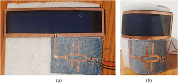
The load-dependent conversion efficiency measured at 1.85 GHz frequency for input power levels is depicted in Fig. 17(a) and it can be seen that the efficiency is greater than 50 and 40%, respectively, for the load resistance between 7.5 and 10 kΩ. The effect of load resistance on power conversion efficiency is studied at both operating frequencies. The power conversion efficiency of the rectifier is increased up to 7.5 kΩ and later it is decreased significantly from 7.5 to 50 kΩ with respect to change in load and the graph is shown in Fig. 17(b). The proposed flexible antenna performance and a comparison of proposed work with other reported rectenna designs is illustrated in Tables 3 and 4, respectively. The fabricated solar cell rectenna is depicted in Fig. 18(a) as a flat energy harvesting system and in Fig. 18(b) it is bent on polyvinyl chloride (PVC) pipe with a diameter of 11 cm.
(a) Conversion efficiency for input power variation for fixed load. (b) Conversion efficiency for load resistance variation.

(a) Wearable rectenna on thin film solar cell flat position. (b) Wearable rectenna on thin film solar cell bent position (D = 11 cm).

Flexible rectenna performance

Comparison of proposed work with other rectenna designs

Hybrid energy harvesting system
The output voltage of the rectenna circuit is determined by the level of electromagnetic energy available at the receiving antenna. These energy levels are irregular in the environment, thus sometimes rectenna is inadequate to generate required DC voltage. Thus, hybrid energy harvesting is an alternative solution to this problem, where energy from different energy sources like solar, wind, temperature, and vibration. In this paper, the selected solar cells are flexible thin film amorphous silicon, with open-circuit voltage of VOC = 2 V and short circuit current of ISC = 420 mA. In this hybrid energy harvesting system, the DC output of the solar cell is integrated with voltage double rectifier and the schematic of the proposed DC combining circuit is shown in Fig. 19(a).
(a) Solar cell rectenna ADS simulink model. (b) Solar cell connected to RF energy harvesting system.

The RF energy harvesting system and solar cell were connected via an inductor (L 1) in parallel. The values of the L 1, is selected by using an optimization technique in ADS software and the aim of this optimization is minimizing the effect of variations produced by changing solar irradiation on rectifier efficiency. The current generated from solar enters onto the rectifier through the inductor (L 1), because an inductor acts as a short circuit for DC current and at the same time the capacitor (C 1) blocks the DC currents entering into matching circuit. In the prototype, solar cell connections are designed at the backside of cotton jeans and inductor (L 1) and capacitor (C 1) are connected via hole through jeans textile which is illustrated in Fig. 19(b).
The Fig. 20(a) shows the optioned DC output voltage of the combining circuit for different irradiance with an input power level of −5 dBm and for a resistive load of 7.5 kΩ. In practice solar cell is considered as a current source the terminal voltage variation is less effected by irradiation, thus the output voltage is above 1 V at low irradiation conditions (as shown in Fig. 14 600 W/m2).
(a) Measured DC output voltage versus frequency for change in irradiation. (b) Measured power conversion efficiency versus irradiation.

However, the current regenerated by the solar cell is much affected with change in irradiation, so that the power conversion efficiency is less under low irradiation conditions that are depicted in Fig. 20(b). The power conversion efficiency is above 70% for solar cell rectenna with 1.85 GHz RF input and is 65% for solar cell rectenna with 2.45 GHz RF input. Finally, the DC combining circuit performance for different combinations of RF signal is presented in Table 5.
Solar cell Rectenna performance

Conclusion
This paper explains the design and testing of an antenna integrated thin film solar cell and also its potential application in the wearable wireless energy harvesting system. The multilayers in the solar cell encapsulation like EVA, nylon and top layer ETFE are used as a substrate to design the antenna. From the measured results it is clear that the fabricated antenna has a dual band operation and the operating frequencies are 1.85 and 2.45 GHz. Proposed solar cell rectenna performances are investigated for different micropower levels as −30 to 10 dBm along with changing solar irradiation. The rectenna maximum conversion efficiency obtained at 1.85 GHz is 58% for an input power level of −5 dBm with DC output voltage of 0.83 V and the maximum efficiency at 2.45 GHz is 42.6% with an output voltage of 0.57 V. Also the conversion efficiency of the solar cell rectenna is above 50% in the bent condition with measured DC voltage of 1 V. Finally, this wearable harvesting system is suitable for low power and ultra-low power electronic applications and the performance of the system is improved by connecting power control unit like LTC3105 and BQ54405.
 Naresh B received B.Tech. and M. Tech. degrees in Electrical and Electronics Engineering from Jawaharlal Nehru Technological University, Hyderabad, India, in 2006 and 2012, respectively. He is currently pursuing Ph.D. in Electrical engineering from Bhagwant University, Ajmer, Rajasthan, India. He has published more than 25 research papers in renowned International Journals such as IEEE, Springer and published one patent in theOofficial Journal of The Patent Office.
 Prof. (Dr.) V. K. Singh has done B. Tech. in Electrical Engineering from IET Rohilkhand University, Bareilly, UP, M. Tech. in Digital Communication System in 2009 from Bundelkhand Institute of Engineering & Technology, Jhansi, UP and received his Ph.D. in the field of Microstrip Antenna in 2013 from BU Rajasthan. He has more than 16 years of experience in the field of Electrical and Electronics Engineering. Currently, he is working as a Professor and Head in Electrical Engineering Department at S.R. Group of Institutions, Jhansi UP, India. He is a senior member of International Association of Computer Science and Information Technology (IACSIT) and International Association for the Engineers and Computer Scientists (IAENG). He is also a member Institute of Electrical and Electronics Engineers (IEEE). He has been working as a Coordinator of National Programme on Technology Enhanced Learning (NPTEL), IIT Kanpur and also a nodal coordinator of Virtual Labs, Indian Institute of Technology Roorkee. He is a Vice Editor In Chief Blue Eyes Intelligence Engineering & Sciences Publication Pvt. Ltd. (BEI-ESP).
Prof. Singh has published more than 200 research papers in the renowned International Journals such as IEEE, Springer and Willey. He is the author of one edited book of renowned publisher, IGI Global (USA) and two reference books. He has published more than 25 book chapters in Springer and published one patent in the Official Journal of The Patent Office. He has guided six Ph.D. Scholars and More than 30 M.Tech. Students. He has guided for the project selected for financial grant under Council of Science & Technology Govt. of UP (CST UP). He has delivered Experts lectures in many seminar and workshops and has organized many interactive workshops and seminars. He was appointed as the external examiner for Ph.D. defense viva in many universities.
Prof. Singh has chaired the sessions such as IEEE Conference (ICACAT-2018) at LNCT Bhopal, Springer Conference (ICSC-2019) at Institute of Hydro power Engineering and Technology Tehri, Uttarakhand, International conference (ICRESE-2016) at Govt. VYTPG, Raipur C.G.. He is the reviewer of many renowned SCI Journals and International and national conferences.
 Prof (Dr.) V. K. Sharma has done his B.E. from KREC (NIT) Surathkal, M.Tech. and Ph.D. from IIT Delhi. He has done 1-year stint as post-doctoral fellow at École de Technologies Superieure at Montreal Canada. Currently, he is working as a Professor and Vice Chancellor at S.R. Bhagwant University, Ajmer, Rajasthan, India. He is a senior member of Institute of Electrical and Electronics Engineers (IEEE), Life Member of Indian Society for Technical Education (ISTE), Life Fellow of Institute of Electronics and Telecommunication Engineers (IETE), New Delhi and Life Member of Indian Science Congress, Calcutta, India. He has published one patent in the Official Journal of The Patent Office and guided more than 10 Ph.D. Scholars. He has visited more than 20 countries. His research area includes DSP control of electric drives, active filters, power electronics application to power systems and renewable energy conversion techniques, sensor networks, computational algorithms etc.