



1 Introduction
Shape-changing bodies moving in a fluid can generate forces by rapidly imparting momentum to the fluid, provided there is subsequent flow control to avoid uncontrolled separation and ensure the formation of flow patterns conducive to the generation of suitable fluid forces. Marine animals and birds extensively employ shape and volume body change for propulsion and manoeuvering. Small fish have flexible fins that can undergo deformation during a cycle of oscillation, including shape change (Drucker & Lauder Reference Drucker and Lauder2000; Ramamurti et al. Reference Ramamurti, Sandberg, Lohner, Walker and Westneat2002; Dong et al. Reference Dong, Bozkurttas, Mittal, Madden and Lauder2010). Bats employ flexible, shape- and area-changing wings (Hedenstrom, Johansson & Spedding Reference Hedenstrom, Johansson and Spedding2006; Lindhe Norberg & Winter Reference Lindhe Norberg and Winter2006; Wolf et al. Reference Wolf, Johansson, von Busse, Winter and Hedenstrom2010). Squid and octopus employ large volume and shape deformations to power their locomotion and manoeuvering (Packard Reference Packard1969; Muller & Lentink Reference Muller and Lentink2004; Huffard Reference Huffard2006; Polet, Rival & Weymouth Reference Polet, Rival and Weymouth2015). Rowing involves imparting momentum to the fluid through motion of the oars, which are then retracted leaving an energetic wake behind; likewise, insects and lizards can walk on water by submerging and then retracting their legs (Dickinson Reference Dickinson2003; Hsieh & Lauder Reference Hsieh and Lauder2004; Hu & Bush Reference Hu and Bush2010).
Engineering studies have also addressed studying the physics of shape-changing bodies in a fluid. Childress, Vanderberghe & Zhang (Reference Childress, Vanderberghe and Zhang2006) showed that a body with time-varying cross-section within an oscillatory flow can suspend itself against gravity. Spagnolie & Shelley (Reference Spagnolie and Shelley2009) showed that a cylinder with variable frontal area can propel itself within an oscillatory flow by appropriate active phase control. Finally, in cases of matter phase change, for example in moving bubbles that turn from gas to liquid, the initial energy and vorticity generated by the bubble is shed in the fluid (Hunt & Eames Reference Hunt and Eames2002; Eames Reference Eames2008). All these cases involve transfer of added mass-related kinetic energy to the fluid, as well as simultaneous shedding of boundary layer vorticity over large areas of the body, what is termed ‘global vorticity shedding’ (Weymouth & Triantafyllou Reference Weymouth and Triantafyllou2012; Wibawa et al. Reference Wibawa, Steele, Dahl, Rival, Weymouth and Triantafyllou2012).
A foil that is retracted rapidly in the spanwise direction can capture some of the basic features of shape change. In (Wibawa et al. Reference Wibawa, Steele, Dahl, Rival, Weymouth and Triantafyllou2012), a high aspect ratio, square-tipped foil was towed with constant angle of attack and steady speed before being rapidly retracted through the free surface of the tank. This experiment was designed as a model problem for morphing bodies that undergo large shape changes, since the cross-section of the body appears to vanish when viewed from a two-dimensional plane within the tank. The choice for a retracting foil as a representative model of ‘vanishing’ bodies was made because of the simplicity of the experimental set-up, as compared to more elaborate models of deflating or folding bodies. A foil geometry has also the advantage that, at angles of attack below stalling, the foil can impart significant kinetic energy to the surrounding fluid with minimal flow separation. A sharp, square-tipped foil was chosen based on considerations from inviscid slender body theory, where it is known that in order to shed momentum in the wake, a body must have a finite two-dimensional added mass at its trailing edge (Lighthill Reference Lighthill1975), i.e. a sharply ending tip. Additionally, retracting foils have application in the study of rowing propulsion and human swimming.
The results from Wibawa et al. (Reference Wibawa, Steele, Dahl, Rival, Weymouth and Triantafyllou2012) showed that a solid, retracting foil, with a rectangular planar form ending with a sharp, square tip, sheds its boundary layer vorticity and added mass energy as it is being retracted, leaving ultimately two strong columnar vortices parallel to its spanwise direction; as well as an additional vortex ring with its axis in the spanwise direction, formed at its sharp tip. The additional ring vortex introduces significant transient three-dimensional flow structures near the tip of the retracting foil. This vortex ring contains the added mass energy caused by the retraction, which is significant for the studied high retraction speeds. The presence of the vortex ring and the resulting transient structures makes the visualization of the flow difficult through two-dimensional planar cuts. More importantly, the columnar vortices do not remain straight, and under the influence of the vortex ring become significantly distorted. For vorticity control, where oncoming coherent vortices may be manipulated to either enhance forces or recover energy by downstream bodies (Gopalkrishnan et al. Reference Gopalkrishnan, Triantafyllou, Triantafyllou and Barrett1994; Beal et al. Reference Beal, Hover, Triantafyllou, Liao and Lauder2006), this poses difficulties since the orientation of shed columnar vortices does not remain predictable. Hence, finding ways to reduce three-dimensionality are desirable.
Subsequent studies by Weymouth & Triantafyllou (Reference Weymouth and Triantafyllou2012, Reference Weymouth and Triantafyllou2013), addressing bodies undergoing large volume change, showed that two different flow configurations may emerge:
-
(i) A towed deflating body can recover its added mass energy through the generation of a thrust force in the direction of towing, while commensurate vorticity is annihilated in the boundary layer, and hence no vortical patterns are shed in the wake. This is conditioned on avoiding any uncontrolled flow separation, which prevents energy recovery and results instead in energy and vorticity shedding in the wake.
-
(ii) A towed ‘melting’ body sheds its added mass energy and vorticity in the wake forming strong vortical patterns.
A ‘melting’ body is assumed to undergo an orderly and gradual phase change from solid to liquid; and it is similar to a disappearing (vanishing) body, except that it does not require fluid to move in to replace the void that would have been created by a disappearing body. The energy recovery in a deflating body was demonstrated experimentally by Weymouth, Subramaniam & Triantafyllou (Reference Weymouth, Subramaniam and Triantafyllou2015), where an octopus-like robot undergoing deflation to propel itself also recovers its added mass energy, providing a high final escape speed.
In light of these results, the retracting foil is revisited to consider situations under which different volume change configurations as in Weymouth & Triantafyllou (Reference Weymouth and Triantafyllou2012, Reference Weymouth and Triantafyllou2013) may be considered. There is a fundamental difference between a shape-changing body and a retracting rigid foil, where in the former case, kinetic energy and momentum may be shed across the entire body, whereas, in the latter case, energy and momentum may be shed only at the tip (unless flow separation across the body occurs). This necessitates a very rapid retraction of the foil, in order to closely match a global vorticity shedding. In addition, as the foil is accelerated when it is being retracted, additional momentum and energy are introduced to the flow in the direction of retraction, which depends on the projected area of the foil in the same direction. It is to be expected, therefore, that the shape of the tip will have a great impact on the resulting flow field.
It should be noted that when energy and vorticity are shed in the wake, they is potentially recoverable if, for example, the unsteadily moving body re-enters the wake during stroke reversal, such as in flapping flight, in what is termed wake capture (Birch & Dickinson Reference Birch and Dickinson2003); or if the flow is captured by a downstream fin, as in dragonflies (Wang & Sun Reference Wang and Sun2005; Huang & Sun Reference Huang and Sun2007; Lehmann Reference Lehmann2008). Also, in fish swimming, it is shown that the caudal fin operates in the wake of upstream fins, gaining propulsive efficiency through interaction with the oncoming vortices (Zhu et al. Reference Zhu, Wolfgang, Yue and Triantafyllou2002). The ability of bodies to extract energy from oncoming coherent vortices has been demonstrated in Beal et al. (Reference Beal, Hover, Triantafyllou, Liao and Lauder2006), who showed that a dead trout can extract energy from the coherent vortices of an oncoming Kármán street wake generated by a D-shaped cylinder, causing it to surge upstream. The same results were demonstrated with a passive foil in the wake behind a D-shaped cylinder. In order for such energy extraction to occur, it is required that vortices shed by the upstream fins or bodies be coherent and quasi two-dimensional along their axis. Hence the unsteady columnar vortices found in Wibawa et al. (Reference Wibawa, Steele, Dahl, Rival, Weymouth and Triantafyllou2012) are ill-suited for subsequent energy recovery and alternative tip geometries provide a different method for controlling energy deposited in the fluid.
As a result of these considerations, three alternative shapes of retracting foils (figure 1) are studied:
-
(i) A solid, squared-tip foil similar to the foil used in Wibawa et al. (Reference Wibawa, Steele, Dahl, Rival, Weymouth and Triantafyllou2012), which serves as a model of a vanishing body.
-
(ii) A streamlined-tipped foil, which is expected to allow at least partial recovery of added mass energy and hence formation of much weaker vortical structures; in analogy to a deflating body.
-
(iii) A squared tipped but hollow foil, which allows energy and momentum shedding without introducing added energy in the direction of retraction; in analogy with a melting body.
Retraction through the laser plane, dashed green line. (a) Square-tipped foil’s cross-section ‘vanishes’ in the plane. (b) Streamlined-tipped foil’s cross-section ‘shrinks’ in the plane. (c) Hollow foil ‘melts’ in the plane when the thin walls of constant cross-section retract through the plane and leave the internal slug of fluid, as though the foil becomes liquid. Sketches in second row depict ultimate wake shape at laser plane.

2 Energy and vorticity transfer considerations
Within potential flow theory, an accelerating body experiences a reactive force proportional to its acceleration, the added mass force, which is a conservative force; hence the energy expended to accelerate a body may be completely recovered when the body decelerates to rest. In the context of viscous fluid flows, Burgers (Reference Burgers1921) and Biesheuvel & Hagmeijer (Reference Biesheuvel and Hagmeijer2006) consider the resistance experienced by a moving object in a fluid as a function of discrete vorticity impulses generated at the boundary of the object. As time progresses, the vorticity impulse diffuses from the transition layer, advects downstream in the fluid, and a new impulse forms at the boundary, where the resistance exerted on the body is described as the sum of these vortex layer impulses over time. Burgers (Reference Burgers1921) argues that characterizing the force exerted on the body is the same for viscous and inviscid fluid flows, as long as the no-slip boundary condition is satisfied on the surface of the body. A second component associated with the viscous diffusion of vorticity generated on the boundary is irreversible and will be lost to the flow even if the body comes to rest.
The application of the no-slip boundary condition in inviscid flow introduces an infinitely thin vortex sheet on the surface of the body. This vortex sheet never diffuses to the fluid interior as happens in a viscous fluid, since there is no viscosity. In steady state conditions, the strength of the vortex impulse in this sheet remains constant and its strength will only change if the body accelerates or decelerates, introducing a new vortex impulse to the boundary in order to satisfy the no-slip boundary condition. If the body comes to rest, new vortex impulse created at the boundary must cancel the existing vortex impulse.
Added mass forces play a significant role in unsteady locomotion of deformable bodies (Lighthill Reference Lighthill1975; Kanso Reference Kanso2009), especially at large Reynolds number. In the case of a suddenly retracted body (Klein Reference Klein1910), a melting disk (Taylor Reference Taylor1953) or a vanishing body (Hunt & Eames Reference Hunt and Eames2002; Eames Reference Eames2008), the body boundary is presumed to instantaneously disappear, releasing its entire added mass energy and boundary vorticity to the fluid. In viscous flow, added mass energy is also recoverable, as shown in Weymouth & Triantafyllou (Reference Weymouth and Triantafyllou2012, Reference Weymouth and Triantafyllou2013).
For a retracting foil, the release of energy to the fluid will depend on whether the body recovers energy from the fluid during retraction or not. In the case of a ‘shrinking’ foil, the varying foil cross-section can allow for the recovery of energy associated with the added mass of the object as its size decreases, as in Weymouth & Triantafyllou (Reference Weymouth and Triantafyllou2012, Reference Weymouth and Triantafyllou2013). By contrast, suddenly ‘vanishing’ and ‘melting’ objects have boundaries which instantaneously vanish from the fluid, and hence there can be no mechanism for the added mass energy to be recovered by the object; this energy is released to its wake along with the vorticity in the boundary layer.
The breakdown of the hydrodynamic forces exerted on a body is expressed through Lighthill (Reference Lighthill1986)’s force expression:
 $$\begin{eqnarray}\displaystyle \boldsymbol{D}=-\frac{\text{d}\boldsymbol{I}}{\text{d}t}=\frac{\text{d}}{\text{d}t}\left(\unicode[STIX]{x1D70C}\int _{S_{B}}\unicode[STIX]{x1D719}\boldsymbol{n}\,\text{d}S\right)-\frac{\text{d}}{\text{d}t}\left(\frac{1}{2}\unicode[STIX]{x1D70C}\int _{V}\boldsymbol{x}\times \unicode[STIX]{x1D74E}_{a}\,\text{d}V\right), & & \displaystyle\end{eqnarray}$$
where the force
 $\boldsymbol{D}$
is expressed as the change of fluid impulse
 $\boldsymbol{I}$
in time, consisting of an irrotational part represented by a potential function
 $\unicode[STIX]{x1D719}$
integrated over the body surface
 $S_{B}$
with unit normal
 $\boldsymbol{n}$
and density
 $\unicode[STIX]{x1D70C}$
and a rotational part with the first moment of additional vorticity distribution
 $\unicode[STIX]{x1D74E}_{a}$
integrated over the volume
 $V$
. This breakdown of the fluid force based on inviscid and viscous components, however, is difficult to analyse in measured viscous flows since the field cannot be separated into an inviscid and a viscous part. Instead, an extension of Wu, Ma & Zhou (Reference Wu, Ma and Zhou2006)’s boundary vorticity flux theory is employed in § 6.3, which allows for the definition and calculation of contributions to the boundary layer circulation reduction related to the expected differences in energy released to the wake of a ‘vanishing’ object, as compared with a ‘shrinking’ object and a ‘melting’ object.
2.1 Boundary vorticity flux
The boundary vorticity flux
 $\unicode[STIX]{x1D748}$
is equal to the normal component of the gradient of the vorticity
 $\unicode[STIX]{x1D74E}$
at the fluid–solid boundary, multiplied by the kinematic viscosity
 $\unicode[STIX]{x1D708}$
:
 $$\begin{eqnarray}\displaystyle \unicode[STIX]{x1D748}\equiv \unicode[STIX]{x1D708}\boldsymbol{n}\boldsymbol{\cdot }\unicode[STIX]{x1D735}\unicode[STIX]{x1D74E}=\unicode[STIX]{x1D708}\frac{\unicode[STIX]{x2202}\unicode[STIX]{x1D74E}}{\unicode[STIX]{x2202}n}. & & \displaystyle\end{eqnarray}$$
It measures the rate of vorticity creation at the boundary and simultaneous diffusion into the fluid per unit time and area (Wu & Wu Reference Wu and Wu1993, Reference Wu and Wu1998; Wu et al.
Reference Wu, Ma and Zhou2006). The vorticity at the boundary depends on the integrated effect of the boundary vorticity flux over time; thus, if the boundary vorticity and
 $\unicode[STIX]{x1D748}$
are of the same sign, the boundary vorticity magnitude is strengthened. If, instead,
 $\unicode[STIX]{x1D748}$
has opposite sign, then
 $\unicode[STIX]{x1D748}$
acts to weaken the boundary vorticity magnitude, implying cross-diffusive annihilation of vorticity (Morton Reference Morton1984).
The different contributions to vorticity generation at the boundary can be expanded as:
 $$\begin{eqnarray}\displaystyle & \displaystyle \unicode[STIX]{x1D748}=\boldsymbol{n}\times \left(\boldsymbol{a}-\boldsymbol{f}+\frac{1}{\unicode[STIX]{x1D70C}}\unicode[STIX]{x1D735}p\right)+\unicode[STIX]{x1D708}(\boldsymbol{n}\times \unicode[STIX]{x1D735})\times \unicode[STIX]{x1D74E}, & \displaystyle\end{eqnarray}$$
 $$\begin{eqnarray}\displaystyle & \displaystyle \boldsymbol{a}=\frac{\unicode[STIX]{x2202}\boldsymbol{u}}{\unicode[STIX]{x2202}t}+(\boldsymbol{u}\boldsymbol{\cdot }\unicode[STIX]{x1D735})\boldsymbol{u}, & \displaystyle\end{eqnarray}$$
 $\boldsymbol{f}$
is the body force,
 $\unicode[STIX]{x1D70C}$
is the density and
 $p$
is the pressure. The shorthand
 $\boldsymbol{a}$
is used for the material derivative of the fluid velocity
 $\boldsymbol{u}$
, equation (2.4). The contributions of each term from (2.3) can be separated as:
 $$\begin{eqnarray}\displaystyle \left.\begin{array}{@{}c@{}}\displaystyle \unicode[STIX]{x1D748}_{a}=\boldsymbol{n}\times \boldsymbol{a},\\ \displaystyle \unicode[STIX]{x1D748}_{f}=-\boldsymbol{n}\times \boldsymbol{f},\\ \displaystyle \unicode[STIX]{x1D748}_{p}=\frac{1}{\unicode[STIX]{x1D70C}}\boldsymbol{n}\times \unicode[STIX]{x1D735}p,\\ \displaystyle \unicode[STIX]{x1D748}_{vis}=\unicode[STIX]{x1D708}(\boldsymbol{n}\times \unicode[STIX]{x1D735})\times \unicode[STIX]{x1D74E},\end{array}\right\} & & \displaystyle\end{eqnarray}$$
where
 $\unicode[STIX]{x1D748}_{a}$
is the contribution due to tangential fluid acceleration,
 $\unicode[STIX]{x1D748}_{f}$
is the contribution due to the tangential body force,
 $\unicode[STIX]{x1D748}_{p}$
is the contribution due to the tangential pressure gradient and
 $\unicode[STIX]{x1D748}_{vis}$
is a viscous contribution that is non-zero only in three-dimensional flows (Wu et al.
Reference Wu, Ma and Zhou2006).
3 Experimental methodology
The experiments follow a similar procedure to those of Wibawa et al. (Reference Wibawa, Steele, Dahl, Rival, Weymouth and Triantafyllou2012), where a surface piercing foil is towed at a constant angle of attack, allowed to reach a steady forward speed and then quickly moved in the spanwise direction. The foil is viewed using a particle image velocimetry (PIV) system, where the system illuminates the foil and wake in a two-dimensional plane that intersects the foil at a cross-section within the region over which the foil is retracted. This intersection is such that the cross-section of the foil is in the field of view for a portion of the retraction time and out of the field of view for the latter portion of the retraction time. Figure 2 illustrates the general retraction procedure for a given foil.
Schematic of foil retraction in towing tank. The foil is towed at a constant forward speed
 $U$
and retracted with time varying vertical speed
 $W(t)$
. Black solid line shows example foil-tip kinematics within the towing tank and dashed green line shows example position of PIV measurement laser plane.

The foil was initially towed with a constant forward velocity of
 $U=0.2~\text{m}~\text{s}^{-1}$
. An optical trigger was used to start the vertical retraction of the foil, which was controlled by a Copley Controls STA2504 linear motor. The foil tip was initially located at mid depth in the tank to ensure the formation of a clean tip vortex before moving upward in its trajectory, reducing the submerged span of the foil. The towing tank was
 $2.4~\text{m}\times 0.75~\text{m}\times 0.75~\text{m}$
large.
Three separate foil geometries were tested: (i) a constant cross-section, square-tipped, solid foil, (ii) a streamlined-tipped foil where the leading edge, trailing edge and thickness follow an approximate parabolic tapering at the tip of the foil, and (iii) a constant cross-section, square-tipped, thin-walled, hollow foil. The solid square-tipped foil had a constant NACA 0012 cross-section throughout its span. The streamlined-tipped foil had a NACA 0012 cross-section, where starting at one half of a chord length from the tip, the foil tapered off along both the chord and thickness directions. The chord length of both foils was
 $c=68.5~\text{mm}$
and the span was
 $0.43~\text{m}$
. The hollow foil was modified from a hobby helicopter wing, HD800N 800 carbon fibre blade from Align. The cross-section of the commercial foil was symmetric and similar to a NACA 0012 section, with chord length
 $c=68.9~\text{mm}$
, maximum thickness of
 $8.8~\text{mm}$
and span of
 $0.49~\text{m}$
. The wing had thin exterior carbon fibre walls with supporting internal bracing for stiffness. The internal bracing was removed to produce a thin-walled foil with a hollow interior. The geometry of the three foils is shown in figure 3.
Planform (upper row) and cross-section (lower row) views of the (a) solid, (b) streamlined, and (c) hollow, thin-walled foils. The solid and streamlined foils are NACA0012 cross-sections, while the hollow foil has similar thickness to chord ratio of a NACA0012 cross-section.

In the experiments, a laser plane was positioned within the tank to quantitatively measure the wake of the foil as it passes through the laser plane using PIV. In each experiment, the foil followed a cosine or s-curve trajectory during the retraction, while the maximum speed of retraction was varied for different experiments. Details of the experimental set-up including laser plane position, retraction distance and retraction speed are given in table 1 for the different foil configurations. It was found previously (Wibawa et al. Reference Wibawa, Steele, Dahl, Rival, Weymouth and Triantafyllou2012) that as long as the laser plane is positioned near the centre of the retraction region, the resulting velocity field is not statistically different from a slightly different height. Additionally, differences between the cosine and s-curve trajectories were negligible.
Experiment set-up and test parameters.

Experiments were conducted with the foils oriented at an angle of attack of
 $10^{\circ }$
for all foil geometries. Experiments were repeated at least 25 times to obtain a statistically significant number of experiments for averaging. The Reynolds number based on the chord length and forward towing velocity was
 $Re=13\,700$
.
PIV measurements were taken for all foils retracting through the measurement laser plane, shown as a dashed line in figure 2. The laser plane position ensures that the foils have identical cross-sections at the laser plane at the beginning of the foil motion while the cross-sectional shape of the foil evolves in time during retraction, depending on the specific foil model. Time-resolved PIV was performed using a two-dimensional system by LaVision GmbH, which utilized a Quantronix Darwin Nd:YLF
 $\unicode[STIX]{x1D706}=527~\text{nm}$
single-cavity laser and a 10 bit Imager Pro HS CMOS camera. The high speed camera recorded single frames at a frame rate of 600 Hz at a resolution of
 $1200\times 1024$
pixels. The laser plane was approximately
 $2{-}2.5~\text{mm}$
thick and polyamide seeding particles with mean particle diameter of
 $50~\unicode[STIX]{x03BC}\text{m}$
were used. Vector fields for the solid and streamlined-tipped experiments were calculated using multi-pass correlation with the first pass using a
 $32\times 32$
pixels interrogation windows, and a second pass using a
 $16\times 16$
pixels interrogation window, both passes with a
 $50\,\%$
overlap. Vector fields for the hollow experiments were calculated using multi-pass correlation with the first pass using a
 $64\times 64$
pixels interrogation windows, and a second pass using a
 $32\times 32$
pixels interrogation window, both passes with a
 $50\,\%$
overlap. A local median filter was used in order to eliminate outliers, as well as a
 $3\times 3$
median filter to lightly smooth the vector fields. The estimated accuracy of the vector fields was within
 $1\,\%$
of the towing speed (Raffel et al.
Reference Raffel, Willert, Wereley and Kompenhans2007).
Sequence of PIV vorticity plots for the solid, square-tipped foil: non-dimensionalized ensemble-averaged vorticity field
 $\unicode[STIX]{x1D714}_{z}c/U$
, obtained from 25 repeat experiments; at non-dimensional times
 $t^{\ast }=t(U/c)$
as marked, with
 $t^{\ast }=0$
corresponding to the onset of foil retraction. Note that in addition to the originally imparted boundary layer vorticity rolling up to form vortices denoted as A and B, two rapidly growing vortices, denoted as C and D (to correspond to those described in Wibawa et al. (Reference Wibawa, Steele, Dahl, Rival, Weymouth and Triantafyllou2012), their figure 14) appear as early as
 $t^{\ast }=0.01$
that last until
 $t^{\ast }=0.30$
, as a result of the formation of a strong vertical vortex ring: these additional vortices cause the wake to become unsteady and complex.

For each foil geometry, the velocity field was first derived using the PIV algorithm and filtered to produce a smooth velocity. The velocity fields were ensemble averaged to produce an average time history. Finally, the vorticity field was derived from the ensemble-averaged velocity field.
4 Effect of foil shape – experiments
To compare the effect of the foil-tip geometry, the three foils are tested with a high speed retraction rate to investigate the shedding of kinetic energy in their wake. The angle of attack was set at
 $10^{\circ }$
and the retraction velocity was six times the forward towing speed.
4.1 Solid, square-tipped foil
The time evolution of the wake for the solid foil is shown in figure 4. Six snapshots of the ensemble-averaged vorticity field are shown for non-dimensional times
 $t^{\ast }=t(U/c)$
, between 0 and 1, where
 $t^{\ast }=0$
is defined as the time when the foil’s cross-section has first completely vanished from the measurement plane. PIV data for times
 $t^{\ast }<0$
are not shown, as shadows from the presence of the body limit the ability to accurately measure the velocity field surrounding the body.
As seen in figure 4, the boundary layer that is shed from the body to the wake, quickly reconfigures into two vortices, labelled A and B. The stronger intensity vortex B forms at the position where the foil leading edge was prior to retraction. A jet-like flow forms at later times, as an additional vortex structure (consisting of labelled vortices C and D) forms. This secondary structure appears almost immediately after the foil cross-section vanishes from the plane. It was shown in Wibawa et al. (Reference Wibawa, Steele, Dahl, Rival, Weymouth and Triantafyllou2012) that this structure is related to a ring vortex forming near the tip of the foil during the retraction process. The highly transient wake is consistent with the observations from Wibawa et al. (Reference Wibawa, Steele, Dahl, Rival, Weymouth and Triantafyllou2012), where the ring vortex formed in the retraction process is entrained in the wake, leading to increased three-dimensionality. Over a longer period of time,
 $t^{\ast }=0.3{-}1$
, the intensity and unsteadiness of this additional structure reduces, until only two lasting vortex structures are left in the wake.
The positive and negative circulations in the wake of the foil are computed from the PIV measurements with a similar technique as used in Wibawa et al. (Reference Wibawa, Steele, Dahl, Rival, Weymouth and Triantafyllou2012). For each time step, a bounding box is defined to separately bin positive and negative signed vorticity in the wake of the foil, based on the computer velocity field before applying a median filter. The bins only include vorticity regions with magnitudes larger than the ambient vorticity level, based on a simple ambient level test on the data set. The bounding box is chosen to exclude the foil’s downstream wake and the boxes are allowed to advect in time with an advection rate chosen by linearly interpolating manually determined bounding box positions. The vorticity field within a given bounding box is numerically integrated to determine the separate positive and negative circulations.
Figure 5 shows the total positive, total negative and net non-dimensional circulation for the solid square-tipped foil geometry at time instances
 $t^{\ast }=0{-}1$
. Before retraction, by Kelvin’s law, the net circulation is directly related to the steady lift. The total positive and total negative circulations, however, left in the wake are related to the hydrodynamic impulse (Biesheuvel & Hagmeijer Reference Biesheuvel and Hagmeijer2006) and also depend on the retraction speed of the foil and the foil geometry. More specifically, if there is energy recovery, then there is also vorticity annihilation; thus the total positive or total negative circulation in the wake may differ. Due to these reasons, one would expect differences between measured positive/negative circulations in Wibawa et al. (Reference Wibawa, Steele, Dahl, Rival, Weymouth and Triantafyllou2012) and the present study due to differences in the retraction distances and accelerations.
For reference, a potential flow estimate of the expected positive, negative and net circulation in the wake of the foil is given in figure 5 as well. The theoretical estimate is based on lift characteristics computed for a Joukowski foil that most closely matches the geometry (chord length and thickness) of the NACA 0012 profile. The positive and negative circulations are obtained by computing the circulation based on a line integral along the body surface between the stagnation points of the Joukowski foil (Milne-Thomson Reference Milne-Thomson1968). The potential flow estimate also includes downwash effects for the different foil geometries from expected tip vortex formations (Lighthill Reference Lighthill1986), with details of the calculation given in the appendix. The downwash effects are negligible between the different foil geometries, such that the potential flow circulation estimates are nearly indistinguishable for all foil geometries.
Total positive, total negative and net circulations averaged over 25 runs for the solid, square-tipped foil. Dashed lines show circulation estimates from potential flow for an equivalent Joukowski foil. Total circulations are initially greater than the theoretical estimate due to additional energy induced and shed in the wake by the retraction motion.

As seen in figure 5, the net circulation in the wake of the solid foil matches well with the theoretical expected circulation. This serves to confirm the accuracy of the PIV measurements and computation of circulation in the wake of the foil. For the total positive and total negative circulation, however, there is a discrepancy between the theoretical circulation and the measured circulation, particularly for low
 $t^{\ast }$
. At initial retraction times near
 $t^{\ast }=0$
, the magnitude of the circulation in the wake is much larger than the theoretical value, indicating that the retraction process has increased the energy shed to the wake. As the wake evolves in time, the magnitude of the total positive and total negative circulation decreases, eventually levelling near
 $t^{\ast }>0.7$
with values near the theoretical estimates. It must be noted that the time scales over which the wake evolves are too fast for viscous dissipation to be a significant factor, hence the evolution of the circulation is attributed largely to vorticity annihilation and three-dimensional effects in the wake. Numerical experiments are conducted that support this conclusion.
4.2 Streamlined-tipped foil
Figure 6 shows a markedly different wake evolution for the streamlined-tipped foil. While the solid, square-tipped foil’s wake showed a very energetic, transient condition with several interacting vortical structures, the streamlined-tipped foil’s wake shows a gradual transition of the deposited shear layers into a single lasting vortical structure. The wake is much less energetic and changes over time are much more gradual.
Sequence of PIV vorticity plots for the streamlined-tipped foil: non-dimensionalized ensemble-averaged vorticity field
 $\unicode[STIX]{x1D714}_{z}c/U$
, obtained from 25 repeat experiments; versus non-dimensional time
 $t^{\ast }=t(U/c)$
as marked, with
 $t^{\ast }=0$
corresponding to the onset of foil retraction. Deposited vorticity in the wake gradually reforms into a single vortex structure.

Figure 6 shows the time sequence of vorticity evolution in the wake of the streamlined foil for the same time instances as the solid, square-tipped foil. What is immediately apparent in the wake visualization is that there is no significant transient or secondary vortex formation in the wake attributed with ring vortex formation at the tip. Instead, the boundary layer of the foil sheds immediately and the boundary layer gradually rolls up into a single lasting vortex. The smooth tip of the streamlined foil ensures that additional ring vorticity associated with the retraction motion does not form near the tip, such that the boundary layer is smoothly deposited in the wake. This process is clearly evident in the computation of the circulation.
The positive, negative and net circulations for the streamline-tipped foil are shown in figure 7. Again, the net circulation of the hollow foil matches well with the theoretical circulation estimate. However it is apparent that the wake of the streamlined foil is significantly less energetic, as the magnitude of the total positive and total negative circulation are significantly less than the theoretical estimates. The magnitude of the circulation components slightly decreases over time and remains significantly less than the theoretical estimate of the finite-span square-tipped foil. It is important to note that at time
 $t^{\ast }=0$
, the foil has completely vanished from the plane, so these computations of circulation only show the evolution of circulation in the wake after the foil has disappeared. Since the circulation is observed to be significantly lower than the theoretical estimate at
 $t^{\ast }=0$
, this implies that the smoothly shrinking cross-section of the foil plays a central role in the formation of a reduced energetic wake. Based on previous observations for shrinking bodies (Weymouth & Triantafyllou Reference Weymouth and Triantafyllou2012, Reference Weymouth and Triantafyllou2013), it is concluded that the smoothly shrinking cross-section of the foil results in recovery of most of the added mass energy previously imparted to the fluid during the rapid retraction, such that by the time the foil finally disappears in the plane of observation, very little of the added mass kinetic energy is left in the wake. Again, numerical experiments are performed to shed further light into this process and provide additional information about the forces acting on the body.
Total positive, total negative and net circulations averaged over 25 runs for the streamline-tipped foil. Dashed lines show circulation estimates from potential flow for an equivalent Joukowski foil. Initial and final circulations are lower than the theoretical estimate. This lower circulation is caused by energy recovery to the body from the wake as the cross-section of the body shrinks during retraction.

4.3 Hollow foil
The hollow, square-tipped foil results in a different behaviour of the wake during retraction. With a hollow foil, its interior is filled with a slug of fluid, which is left in the wake when the foil retracts, producing a ‘melting’-like condition. Figure 8 shows the time sequence of the wake vorticity for the hollow foil under similar rapid retraction as for the solid and streamlined foils.
In contrast with the solid foil and similar to the streamlined foil, the initial boundary layer sheds from the tip and then forms lasting vortex structures, without the additional formation of transient secondary vortex structures. Similar to the streamlined foil, the boundary layer simply coalesces into a large vortex structure. In contrast with the streamlined foil, however, the resulting wake is significantly more energetic.
Sequence of PIV vorticity plots for the hollow foil: non-dimensionalized ensemble-averaged vorticity field
 $\unicode[STIX]{x1D714}_{z}c/U$
, obtained from 30 repeat experiments; versus non-dimensional time
 $t^{\ast }=t(U/c)$
as marked, with
 $t^{\ast }=0$
corresponding to the onset of foil retraction. In contrast with the solid foil, no secondary vortex structures form and the wake is structurally similar to that of the streamlined foil, but it is much more energetic because no energy recovery occurs.

The circulation from the wake of the hollow foil is seen in figure 9, where, again, the net circulation is nearly equal to the theoretical estimate. In contrast to the solid and streamlined foils, the positive and negative circulations match well with the theoretical estimates at all times, resulting in an energetic wake that does not involve vorticity annihilation and transient effects. This selectively combines some features from the wakes of the solid and streamlined foils, as the wake is largely energetic, similar to the solid foil, but also the wake vorticity remains relatively constant over time, similar to the streamlined foil. The hollow foil not only provides a very energetic wake, but also allows flow control, as the resulting circulation matches that predicted by the theoretical estimates, while remaining relatively constant over time. Some reduction in the vorticity magnitude does occur at later times, following the rate also observed for the streamlined foil. Since no energy recovery occurs, the wake is energetic because the entire initial added mass energy is shed to the wake. No added mass energy is imparted during the retraction, since the foil is hollow, and hence no vortex ring forms. Again, numerical simulations are performed to provide further detail the flow at the tip.
Total positive, total negative and net circulations averaged over 30 runs for the hollow, square-tipped foil. Dashed lines show circulation estimates from potential flow for an equivalent Joukowski foil. Initial and final circulations are very close to the theoretical estimate. The entire original added mass energy is shed to the wake and no additional energy is imparted during retraction as the foil is hollow.

5 Effect of the retraction rate
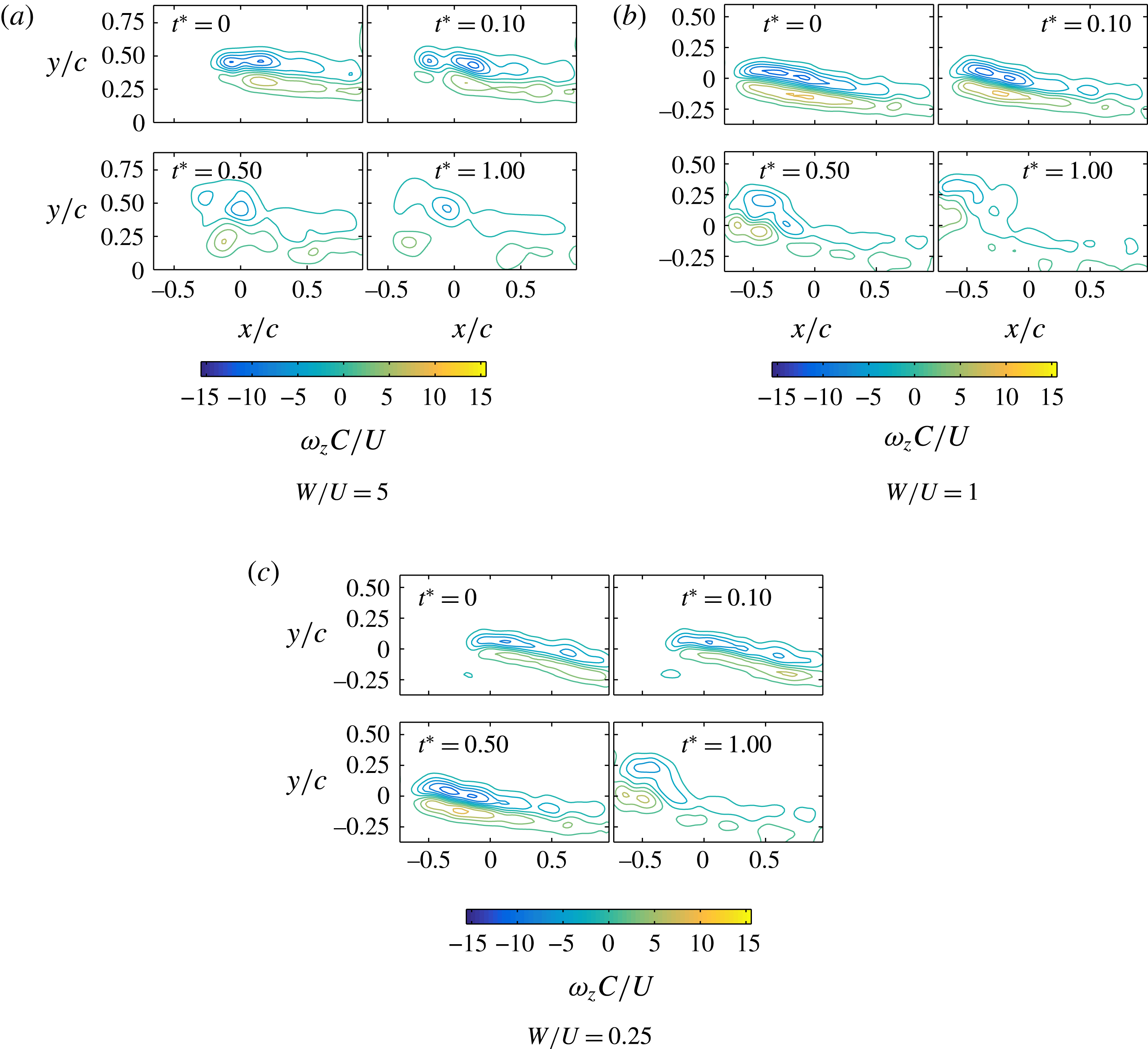
The retraction rate of the foil was also varied in a series of experiments. Since the hollow foil has a qualitatively similar wake to the streamlined foil, only the solid and hollow foils were studied. Three maximum speeds of retraction (
 $W$
) were used, while the forward speed (
 $U$
) was kept constant: (i) a rapid retraction,
 $W/U=6$
for the solid foil and
 $W/U=5$
for the hollow foil, (ii) a moderate retraction,
 $W/U=1$
and (iii) a slow retraction,
 $W/U=0.25$
.
Figure 10 shows the time history for the solid foil wake at the three retraction rates tested. At the highest retraction rate, a highly energetic wake and secondary vorticity formation result, as the tip ring vortex is dragged through the PIV plane. At the moderate retraction rate, a strong ring vortex does not form and the resulting wake appears similar to that of the hollow foil at high retraction speeds. At the lowest retraction rate, shedding of the boundary layer only appears for a short time after the disappearance of the foil from the observation plane; it appears that the tip vortex is simply dragged through the laser plane. Hence, the retraction rate has a significant effect on the shedding and evolution of the vorticity of the boundary layer in the wake of the solid foil.
Time history of the solid foil wake for varying retraction rates (
 $W/U$
). Shedding of the entire initial boundary layer vorticity is apparent for the fast and moderate retraction rates only; a vortex ring appears only for the fast retraction.

The behaviour of the hollow foil is quite different than that of the solid foil, as shown in figure 11. For all three retraction rates, the resulting wake is similar, showing a boundary layer that re-forms into two large vortex structures and is independent of the retraction rate for the speeds tested.
Time history of the hollow foil wake for varying retraction rates (
 $W/U$
). Shedding of the entire initial boundary layer vorticity is apparent for all retraction rates.
6 Numerical results
To provide a global, three-dimensional view of the wake, numerical simulations are performed.
6.1 Numerical methodology
Three-dimensional flow simulations were performed for the same kinematic conditions as for the PIV experiments with the highest retraction rate for all three foil geometries. For the hollow foil, the internal fluid flow of the foil was prescribed with the thickness of the solid walls set to
 $c/100$
, similar to the internal flow’s boundary layer thickness. This procedure follows a similar method in Weymouth & Triantafyllou (Reference Weymouth and Triantafyllou2013).
Simulations were performed using the boundary data immersion method, a robust immersed boundary method implemented on a Cartesian grid, specifically developed for fluid–body interactions (Weymouth & Yue Reference Weymouth and Yue2011; Maertens & Weymouth Reference Maertens and Weymouth2015). The method is well validated for foils with very similar grid spacing and resolution (Maertens & Weymouth Reference Maertens and Weymouth2015), as well as dynamic deforming bodies (Weymouth & Triantafyllou Reference Weymouth and Triantafyllou2012, Reference Weymouth and Triantafyllou2013). Based on previous convergence studies with 100 grid points per chord length near the foil (Maertens & Weymouth Reference Maertens and Weymouth2015), the resolution is chosen to be 96 points across the chord length of the foil. An adaptive time-stepping scheme was used, with an average step of approximately
 $0.1(\unicode[STIX]{x0394}x/U)$
. The simulation was performed at
 $Re=1000$
. The simulations were performed in the frame of reference of the foil, with appropriate acceleration correction terms, and, as with PIV measurements,
 $t^{\ast }=0$
is defined as the time that the foil tip crosses the corresponding laser measurement plane and disappears from the plane of interest. The plane for numerical analysis is set at
 $c$
. The numerical simulations were performed at an angle of attack of
 $10^{\circ }$
, consistent with the experiments.
6.2 Comparison with experimental results
First, in order to compare the simulations to the experimental results, the circulation of the simulation data in the equivalent laser plane is calculated using the same method as applied for the experiments. Figure 12 shows the time evolution of the circulation for the solid and streamlined foil geometries. As with the experiments, the positive, negative, and net circulation are given.
Total positive, total negative and net circulations for solid and streamlined foils determined from numerical simulation. Calculations are made in a plane corresponding to the fixed laser plane from experiments.
 $Re=1000$
.

Four observations are noted in comparison with the experiments:
-
(i) Under steady towing, the difference in Reynolds number between simulation and experiments provides different (but consistent) circulation and resulting lift coefficient for an angle of attack of
 $10^{\circ }$
. The non-dimensional net circulation determined from simulations is
$-0.18$
at
$Re=1000$
, giving a lift coefficient of
$C_{L}\approx 0.36$
, while the circulation from the experiments is
$-0.35$
at
$Re=13\,700$
, giving a lift coefficient of
$C_{L}\approx 0.7$
. Indeed, experimental measurements from Alam et al. (Reference Alam, Zhou, Yang, Guo and Mi2010) for a NACA 0012 foil give lift coefficient for
$Re=5300$
to be
$C_{L}\approx 0.35$
and for
$Re=10\,500$
to be
$C_{L}\approx 0.6$
.
-
(ii) Simulation provides the circulation for
$t^{\ast }<0$
. There is a significant increase in the magnitude of the positive and negative circulation for the solid foil during the retraction process (near
$t^{\ast }=0$
). This increase is consistent with the observations from the experiments, where circulations are observed to be higher than the theoretical estimate for the solid foil. The circulation magnitudes for the streamlined foil decrease for
$t^{\ast }<0$
, again consistent with experimental observations where the circulation is observed to be less than the theoretical estimate. -
(iii) Once the streamlined-tipped foil has vanished from the observation plane, for
$t^{\ast }>0$
the magnitude of the positive and negative circulations remain relatively constant over the remaining time. This observation is consistent with the observations from the PIV measurements; however, the PIV measurements showed a slight decrease in the magnitude of circulations over time, rather than a consistently flat value. This may be due to increased turbulent mixing at the higher Reynolds number. -
(iv) The reduction in the circulation is closely associated with the mechanism of energy recovery by the body. During ‘shrinking’, as circulation is reduced, a line integration of
$-p\boldsymbol{n}$
around the instantaneous foil cross-section in the plane shows that there is a large thrust force on the cross-section, see figure 13. This fluid force does positive work on the body, hence, the energy is recovered by the body. The lower pressure at the leading edge generates an in-plane tangential pressure gradient
$\unicode[STIX]{x1D70E}_{p,z}$
on the foil that produces opposite-sign
$z$
-vorticity, which partially annihilates the boundary layer vorticity.


(a) Pressure force distribution
 $-p\boldsymbol{n}_{body}$
around the instantaneous foil cross-section in the plane (scaled by 4). (b) Horizontal pressure force on the cross-section. (c) Fluid-normal arrows of in-plane tangential pressure gradient
 $\unicode[STIX]{x1D70E}_{p,z}$
(scaled by 50).

It should be noted that the difference in Reynolds number between experiment and simulation is reflected in the difference in circulation and hence lift coefficient before retraction. However, the principal physical mechanism during retraction is the shedding of the initial added mass energy, and hence the resulting wakes are similar.
6.3 Circulation balance
As the simulations demonstrate good qualitative comparison with experiments, a detailed analysis of the wake circulation can give a better understanding of the differences in energy transfer among the foil-tip geometries. In this section, Wu et al. (Reference Wu, Ma and Zhou2006)’s boundary vorticity flux theory is extended to estimate the circulation balance for the streamlined-tipped foil. The theory is modified to apply specifically to the
 $z$
-component of vorticity observed in the two-dimensional laser plane.
First consider the vorticity transport equation,
 $$\begin{eqnarray}\displaystyle \frac{\unicode[STIX]{x2202}\unicode[STIX]{x1D74E}}{\unicode[STIX]{x2202}t}+(\boldsymbol{u}\boldsymbol{\cdot }\unicode[STIX]{x1D735})\unicode[STIX]{x1D74E}=(\unicode[STIX]{x1D74E}\boldsymbol{\cdot }\unicode[STIX]{x1D735})\boldsymbol{u}+\unicode[STIX]{x1D708}\unicode[STIX]{x1D6FB}^{2}\unicode[STIX]{x1D74E}, & & \displaystyle\end{eqnarray}$$
along with the divergence theorem and kinematic transport theorem.
Integrating (6.1) over a non-material plane surface domain area
 $D(t)$
with its bounding contour
 $C(t)$
gives
 $$\begin{eqnarray}\displaystyle \int _{D(t)}\frac{\unicode[STIX]{x2202}\unicode[STIX]{x1D74E}}{\unicode[STIX]{x2202}t}\,\text{d}A=-\int _{D(t)}(\boldsymbol{u}\boldsymbol{\cdot }\unicode[STIX]{x1D735})\unicode[STIX]{x1D74E}\,\text{d}A+\int _{D(t)}(\unicode[STIX]{x1D74E}\boldsymbol{\cdot }\unicode[STIX]{x1D735})\boldsymbol{u}\,\text{d}A+\int _{D(t)}\unicode[STIX]{x1D708}\unicode[STIX]{x1D735}\boldsymbol{\cdot }\unicode[STIX]{x1D735}\unicode[STIX]{x1D74E}\,\text{d}A. & & \displaystyle\end{eqnarray}$$
Applying the divergence theorem to the last term on the right-hand side of (6.2) gives
 $\oint _{C(t)}\unicode[STIX]{x1D708}\boldsymbol{n}\boldsymbol{\cdot }\unicode[STIX]{x1D735}\unicode[STIX]{x1D74E}\,\text{d}s$
, where the integrand is recognized as
 $\unicode[STIX]{x1D748}$
.
The two-dimensional PIV plane measurements capture only the
 $z$
-component of vorticity; thus the circulation balance must reflect changes in the
 $z$
-component of vorticity in a non-material surface. Taking the
 $z$
-component of the modified vorticity transport equation gives
 $$\begin{eqnarray}\displaystyle \int _{D(t)}\frac{\unicode[STIX]{x2202}\unicode[STIX]{x1D714}_{z}}{\unicode[STIX]{x2202}t}\,\text{d}A=-\int _{D(t)}(\boldsymbol{u}\boldsymbol{\cdot }\unicode[STIX]{x1D735})\unicode[STIX]{x1D714}_{z}\,\text{d}A+\int _{D(t)}(\unicode[STIX]{x1D74E}\boldsymbol{\cdot }\unicode[STIX]{x1D735})\text{w}\,\text{d}A+\oint _{C(t)}\unicode[STIX]{x1D70E}_{z}\,\text{d}s, & & \displaystyle\end{eqnarray}$$
where the components of vorticity are
 $(\unicode[STIX]{x1D714}_{x},\unicode[STIX]{x1D714}_{y},\unicode[STIX]{x1D714}_{z})$
, the components of velocity are
 $(u,v,\text{w})$
, and the
 $z$
-component of
 $\unicode[STIX]{x1D748}$
is
 $\unicode[STIX]{x1D70E}_{z}$
, accounting for the change of
 $z$
-vorticity within the plane area
 $D(t)$
, due to vorticity convection, vortex tilting and stretching and vorticity creation terms.
If the plane domain area
 $D(t)$
moves in time, the kinematic transport theorem must be applied in order to express the change rate of circulation inside
 $D(t)$
,
 $$\begin{eqnarray}\displaystyle \frac{\text{d}}{\text{d}t}\unicode[STIX]{x1D6E4}_{D}(t)=\frac{\unicode[STIX]{x2202}}{\unicode[STIX]{x2202}t}\int _{D(t)}\unicode[STIX]{x1D714}_{z}\,\text{d}A=\int _{D(t)}\frac{\unicode[STIX]{x2202}\unicode[STIX]{x1D714}_{z}}{\unicode[STIX]{x2202}t}\,\text{d}A+\oint _{C(t)}\unicode[STIX]{x1D714}_{z}U_{n}\,\text{d}S, & & \displaystyle\end{eqnarray}$$
where
 $U_{n}$
is the normal velocity of the contour
 $C(t)$
.
Combining (6.3) and (6.4) into
 $$\begin{eqnarray}\displaystyle \frac{\text{d}}{\text{d}t}\unicode[STIX]{x1D6E4}_{D}(t)=\oint _{C(t)}\unicode[STIX]{x1D714}_{z}U_{n}\,\text{d}S-\int _{D(t)}(\boldsymbol{u}\boldsymbol{\cdot }\unicode[STIX]{x1D735})\unicode[STIX]{x1D714}_{z}\,\text{d}A+\int _{D(t)}(\unicode[STIX]{x1D74E}\boldsymbol{\cdot }\unicode[STIX]{x1D735})\text{w}\,\text{d}A+\oint _{C(t)}\unicode[STIX]{x1D70E}_{z}\,\text{d}s & & \displaystyle\end{eqnarray}$$
accounts for the total time rate of change of circulation in the
 $z$
-direction inside a moving surface plane domain
 $D(t)$
. For the right-hand side of (6.5): the first term is the time rate of circulation change due to convection from the moving domain area, the second term is the change due to in-plane and out-of-plane convection of
 $\unicode[STIX]{x1D714}_{z}$
, the third term is the change due to tilting and stretching of the vorticity lines and the fourth term is the change due to boundary vorticity flux.
6.4 Circulation reduction
Figure 14 shows the shrinking foil cross-section at the laser plane for several time instances. Arrows on the surface of the foil show the
 $z$
-component of the boundary vorticity flux,
 $\unicode[STIX]{x1D70E}_{p,z}$
generated as a function of the changing pressure gradient on the foil. Arrows pointing into the body denote production of positive-signed vorticity. In regions where boundary vorticity flux is positive and the vorticity near the body is negative, cross-diffusive annihilation will occur, reducing the circulation. This condition can be seen for
 $t^{\ast }=0.07$
at the leading edge of the foil, where negative field vorticity is accompanied by a positive boundary vorticity flux on the top side of the foil and a positive field vorticity is accompanied with a negative boundary vorticity flux on the bottom of the foil.
Simulation results for the vorticity contour plots in the laser plane during foil retraction at angle of attack
 $10^{\circ }$
. Superimposed are fluid-normal arrows of
 $\unicode[STIX]{x1D70E}_{p,z}$
(scaled by 50).

Figure 15 shows the breakdown of components of the out-of-plane convective field, the
 $z$
-component of the second term in (6.5). Area integrals are computed over bounding regions where positive (red) or negative (blue) field vorticity exists. The out-of-plane convection is activated by spanwise motion of the foil and resulting shrinking of the foil cross-section in the plane, as the field values are large only when the
 $(\unicode[STIX]{x2202}\unicode[STIX]{x1D714}_{z}/\unicode[STIX]{x2202}z)(c^{2}/U)$
field is large. The out-of-plane field indicates that as the streamlined foil retracts, the boundary layer vorticity below the plane is being pulled up to increase the overall circulation in the plane. As the foil retracts, fluid is entrained in the wake, which acts to pull vorticity upward in the wake of the foil.
Out-of-plane convective term of (6.5), shown in the laser plane for angle of attack
 $10^{\circ }$
. Columns show fields at
 $t^{\ast }=-0.09,-0.07,-0.05$
. First row shows vorticity contours, illustrating the bounding domains for the area integrals (in red and blue thin lines); second and third rows show constituent fields of convective term; fourth row shows total convective field. All values are non-dimensionalized.

For the same time instances, figure 16 shows the breakdown of the
 $z$
-component of the tilting field, the third term in (6.5). The tilting field values are only large when the velocity change with respect to the
 $z$
-direction is large. The field values are then significant only when the cross-section is changing size. The tilting field corresponds to
 $x$
- and
 $y$
-direction vortex tubes that are produced during retraction and reoriented so that there is a
 $z$
-direction contribution that annihilates existing
 $z$
-direction vorticity in the plane.
Non-dimensionalized out-of-plane tilting term of (6.5) in the laser plane for simulations at angle of attack
 $10^{\circ }$
. Columns show fields at
 $t^{\ast }=-0.09$
,
 $-0.07$
,
 $-0.05$
. Red and blue thin lines illustrate the bounding domains for the area integrals. First four rows show constituent fields of tilting term, fifth row shows total tilting field.

6.5 Three-dimensional flow characteristics
Figure 17 shows the three-dimensional structure of the foil wake for the three simulated geometries. Two time instances during the retraction process are shown for the three foil geometries. For each time frame shown in figure 17, two images of the foil are shown to illustrate the wake. The left image shows the vortex cores in the wake of the foil as determined based on the
 $\unicode[STIX]{x1D706}_{2}$
criteria of Jeong & Hussain (Reference Jeong and Hussain1995). The right image of the foil shows coloured iso-surfaces of the vertical component of the vorticity to indicate both rotation direction in the wake and to help indicate where the shed boundary layer exists in the wake since the
 $\unicode[STIX]{x1D706}_{2}$
criteria will threshold flow regions with less rotation. The initial times shown for the simulations are
 $t^{\ast }=0$
, for the solid and streamlined foils and
 $t^{\ast }=0.08$
for the hollow foil; the different value for the latter is chosen since the laser planes matching that of the experiments are at slightly different locations due to a slight difference in rapid retraction rate for the hollow foil. The later times,
 $t^{\ast }=0.19$
for the solid and streamlined foils, and
 $t^{\ast }=1.1$
for the hollow foil, are shown to illustrate the evolution of the wake over time; the longer time for the hollow foil is chosen to allow sufficient time for the long-lasting, stable columnar vortices to form. Supplementary movies of the simulations are made available online at http://dx.doi.org/10.1017/jfm.2016.553.
Visualization of the wake for three-dimensional simulation of the three foil geometries. For each image, on the left vortex cores are shown in white, as determined from
 $\unicode[STIX]{x1D706}_{2}$
criteria (Jeong & Hussain Reference Jeong and Hussain1995). On the right non-dimensional vorticity
 $\unicode[STIX]{x1D714}_{z}(c/U)$
is shown. Fluid flow is travelling left to right, while the foil is retracted in the vertical direction. Dashed line indicates laser plane position for force and vorticity calculations.

A difference in the three-dimensional wake of the three foil geometries is apparent in figure 17, consistent with the observations from the experiments. The solid foil geometry displays a complex wake, where strong vortical structures intertwine in the wake of the foil. A ring vortex forms at the tip of the foil, entraining vorticity and leading to an energetic, but transient and less organized wake. In contrast, the streamlined foil shows a significantly less energetic wake, with a single vortex core following the foil-tip trajectory. The hollow foil displays two strong, columnar vortex cores forming in the wake of the foil, while a ring vortex does not form at the tip of the foil. The lack of the ring vortex for the hollow foil allows the columnar vortex cores to remain stable, leading to an energetic, but significantly more organized wake than for the solid foil.
A principal difference between the wake of the solid foil from the wakes of the streamlined and hollow foils on the other, is the presence of the strong, vertically moving vortex ring. This ring results from the shedding of the additional added mass energy that is imparted by the retraction velocity. This difference is also reflected in the vertical (spanwise) force that each retracting body feels. While the streamlined-tipped foil and hollow foils would both be expected to generate small spanwise forces from primarily friction drag, the square-tipped foil would be expected to experience a much larger spanwise force from friction and form drag.
Like the streamlined case, which behaves like a shrinking body, the hollow case, which behaves like a melting body avoids entrainment of additional ring vortex energy. The ‘melting’ hollow foil does not impart added mass energy as it moves in the spanwise direction, and hence no vortex ring forms.
Finally, while both streamlined and hollow foils shed wakes where the boundary layer evolved into predictable lasting vortex structures, the different tip geometries result in significantly different energy levels in the wakes. The ‘shrinking’ disappearance condition allows recovery of added mass energy, such that the wake is much less energetic, while the ‘melting’ condition of the hollow foil allows for a larger release of added mass energy to the wake. This has a significant implication on the control of energy release while maintaining a predictable vortex structure in the wake of the foil.
7 Discussion
By contrasting the flows generated by retracting the three different foils used in this study, it is found that the shape of the tip can change significantly the flow features and hence the associated forces. The influence of the tip shape features is so large because the retraction speed is high and flow separation happens at the tip. Depending on whether added mass energy is recovered or not, the vortical structures left behind the tip can vary substantially. As shown with the solid foil, if the retraction speed is reduced, the fundamental behaviour of the tip flow changes significantly. Indeed, ensemble-averaged wake vorticity fields and in-plane circulation calculations from PIV show that major differences exist in the shed wake structures as well as energy release among the retracting solid square-tipped, streamlined-tipped and hollow foil geometries.
It is found that a rectangular, sharp-edged solid foils sheds added mass energy in the fluid, generating strong columnar vortices, formed at the foil tip and parallel to the span of the foil, but also forms a vertically moving strong vortex ring that distorts the columnar vortices and causes strong transient effects. The basic flow mechanism is close to that of a vanishing body.
A hollow rectangular foil does not impart additional momentum in the direction of retraction and hence the flow remains stable and lacks the strong three-dimensional, transient effects noted in Wibawa et al. (Reference Wibawa, Steele, Dahl, Rival, Weymouth and Triantafyllou2012). In flow control applications where it may be desirable to quickly shed an energetic wake, the hollow foil is energetically superior, as it requires much less energy to retract. More importantly, the resulting columnar vortices remain two-dimensional and may be used for subsequent force enhancement or energy recovery by another foil or body. The hollow foil is a suitable geometry for releasing significant energy to the fluid to form stable, orderly vortical structures. It combines the advantages of near-complete transfer of the initial added mass-related energy to the wake, with a stable and simple, cleanly evolving wake, similar to that left by the retracting streamlined-tipped foil, but far more energetic. In addition, the hollow foil is capable of exhibiting this behaviour independent of the spanwise retraction speed. There is close analogy of the properties of the hollow foil with those of a melting body.
As discussed in the Introduction, after the body has retracted, the energetic wake left behind in the fluid can be used to generate forcing on other bodies still in the fluid. Another example of how the wake could be used is inspired by a swift’s aerial acrobatics: swifts are able to ‘turn on a dime’ without reducing much cruising speed (Muller Reference Muller2004). At small angles of attack, the wings of a swift generate stable leading edge vortices (LEVs) close to the body that may be used to manipulate acrobatic manoeuvers (Videler, Stamhuis & Povel Reference Videler, Stamhuis and Povel2004). In both the dead trout and swift example, coherence of the vortical structures producing forces is key. For fish swimming behind rocks, the bluff rock produces a coherent Kàrmàn street. For the swift, the LEVs are coherent and stably attached to the hand wing.
Finally, it is found that a streamlined-tip foil recovers partially the initial added mass energy, and most of the added mass energy in the direction of retraction, resulting in weaker columnar vortices, which are stable. The streamlined-tipped foil has a gradually tapered tip that allows energy to be recovered through a positive pressure gradient acting on the smooth-tip profile, in the direction of motion, also generating opposite-sign vorticity, hence partially annihilating the vorticity. Through the pressure gradient, the original added mass energy is partially recovered, as well as the energy imparted in the spanwise direction. As a result, no vortex ring forms, while the reduced released energy results in a stable, but also a less energetic wake. Simulation results shed light on the cause of the reduced entrained wake energy; the loss of energy in the shed wake is manifested as transferred energy back to the foil through a pressure gradient resulting in a thrust force. Circulation balance calculations show that the loss of energy from the flow to the body is also associated with both pressure gradient-induced vorticity annihilation as well as vorticity tilting-induced annihilation, whereby opposite-sign vorticity, which is created on the boundary, immediately cross-diffusively annihilates with existing boundary vorticity. Opposite-sign vorticity is generated by the same pressure gradient that produces the thrust force, and which is similar to that of a shape-changing ‘shrinking’ object (Weymouth & Triantafyllou Reference Weymouth and Triantafyllou2013). There is close analogy with a deflating (shrinking) body, although energy recovery is less for the rapid retraction used.
8 Conclusions
We study experimentally and through simulation, the flow generated by foils towed at an angle of attack of
 $10^{\circ }$
at steady speed, that are rapidly retracted by a certain distance in the spanwise direction. Three different foils with distinct tip shapes are studied, (i) a rectangular sharp-edge solid foil; (ii) a rectangular sharp-edge hollow foil; and (iii) a foil with a smoothly tapering edge. The basic mechanism controlling the flow features in the foils studied are those of added mass energy release and recovery, and rapid vorticity shedding. We show that the foils can serve as simple but effective models of shape- and volume-changing bodies:
-
(i) A foil with rectangular planform and sharply edged tip sheds its added mass energy in the fluid, generating strong columnar vortices, formed behind the tip and parallel to the span of the foil. A solid foil imparts additional energy in the form of a ring vortex, causing the wake to become unstable.
-
(ii) A hollow foil forms a strong wake but does not impart additional momentum in the direction of retraction, and hence the flow remains stable, and does not exhibit the strongly three-dimensional, transient effects noted in Wibawa et al. (Reference Wibawa, Steele, Dahl, Rival, Weymouth and Triantafyllou2012). Hence, it is energetically superior for flow control applications, as it requires much less energy to retract the foil. The resulting columnar vortices remain straight and coherent and can be used for subsequent force enhancement or energy recovery by another foil or body. The behaviour is found to be independent of the retraction speed. There is close analogy of the properties of the hollow foil with those of a melting body as found in Weymouth & Triantafyllou (Reference Weymouth and Triantafyllou2012).
-
(iii) A streamlined-tip foil recovers a significant part of the added mass energy resulting in much weaker columnar vortices, which are also stable and coherent as the added momentum in the direction of retraction is relatively small. A positive pressure gradient and hence a thrust force is found to develop during retraction, which constitutes the mechanism of energy recovery, in complete analogy with the findings of Weymouth & Triantafyllou (Reference Weymouth and Triantafyllou2013) for a deflating body.
Acknowledgements
The authors wish to acknowledge support from the Singapore-MIT Alliance for Research and Technology under the CENSAM project.
Supplementary movies
Supplementary movies are available at http://dx.doi.org/10.1017/jfm.2016.553.
Appendix A. Potential flow circulation estimates with downwash
Calculation of the total positive, negative and net circulation expected for a NACA 0012 foil are based on potential flow estimates of an equivalent Joukowski foil. The Joukowski foil is chosen to match chord length and minimize differences between the thickness of the NACA 0012 section and Joukowski section. Given that the tip vortex on a finite-span wing will reduce the angle of attack experienced by the wing, Lighthill (Reference Lighthill1986) gives a method to calculate the effective angle of attack,
 $\unicode[STIX]{x1D6FC}^{\prime }$
assuming downwash effects.
The tip vortex is modelled according to a two-dimensional velocity potential
 $\unicode[STIX]{x1D719}_{T}$
allowing variable vortex strength
 $k(X)\,\text{d}X$
at positions over the wake of the foil,
 $x=X$
and
 $y=0$
. For a foil span of
 $2b$
, the total potential is given as:
 $$\begin{eqnarray}\displaystyle \unicode[STIX]{x1D719}_{T}=\int _{-b}^{b}\frac{k(X)}{2\unicode[STIX]{x03C0}}\tan ^{-1}\left(\frac{y}{x-X}\right)\,\text{d}X. & & \displaystyle\end{eqnarray}$$
Knowing that the trailing vorticity will produce an induced velocity component at the leading edge of the wing, the induced velocity is defined as
 $\unicode[STIX]{x2202}\unicode[STIX]{x1D719}_{T}/\unicode[STIX]{x2202}y|_{y=0}$
, where:
 $$\begin{eqnarray}\displaystyle \left.\frac{\unicode[STIX]{x2202}\unicode[STIX]{x1D719}_{T}}{\unicode[STIX]{x2202}y}\right|_{y=0}=-2U\unicode[STIX]{x1D700}(x), & & \displaystyle\end{eqnarray}$$
and the angle
 $\unicode[STIX]{x1D700}(x)$
is considered to be small.
If the angle of attack with respect to the free stream is given as
 $\unicode[STIX]{x1D6FC}$
and the effective angle of attack with respect to the total velocity is
 $\unicode[STIX]{x1D6FC}^{\prime }$
, then the following holds:
 $$\begin{eqnarray}\displaystyle \unicode[STIX]{x1D6FC}^{\prime }=\unicode[STIX]{x1D6FC}-\unicode[STIX]{x1D700}(x). & & \displaystyle\end{eqnarray}$$
For the present experiments,
 $\unicode[STIX]{x1D6FC}^{\prime }=0.77\unicode[STIX]{x1D6FC}$
for the solid and hollow foils.
For the two-dimensional lift on a wing, standard potential flow theory based on the Kutta–Joukowski relation gives:
 $$\begin{eqnarray}\displaystyle \unicode[STIX]{x1D6E4}=\unicode[STIX]{x03C0}cU\sin (\unicode[STIX]{x1D6FC}^{\prime }), & & \displaystyle\end{eqnarray}$$
where
 $c$
is the chord length of the airfoil and
 $U$
is the free stream velocity.
Finally, from the Joukowski transform for the equivalent foil, the stagnation points may be found on the unit circle:
 $$\begin{eqnarray}\displaystyle & \displaystyle \unicode[STIX]{x1D703}_{1}=\sin ^{-1}\left(\frac{\unicode[STIX]{x1D6E4}}{4\unicode[STIX]{x03C0}Ua}\right), & \displaystyle\end{eqnarray}$$
 $$\begin{eqnarray}\displaystyle & \displaystyle \unicode[STIX]{x1D703}_{2}=\unicode[STIX]{x03C0}-\unicode[STIX]{x1D703}_{1}. & \displaystyle\end{eqnarray}$$
Integrating the tangential velocity on the surface of the circle between the two stagnation points, the expected values of the total positive and total negative circulations may be found:
 $$\begin{eqnarray}\displaystyle \unicode[STIX]{x1D6E4}_{+}=2aU(\cos (\unicode[STIX]{x1D703}_{1})-\cos (\unicode[STIX]{x1D703}_{2}))+\unicode[STIX]{x1D6E4}(\unicode[STIX]{x1D703}_{1}-\unicode[STIX]{x1D703}_{2}+2\unicode[STIX]{x03C0})/2\unicode[STIX]{x03C0}, & & \displaystyle\end{eqnarray}$$
and
 $$\begin{eqnarray}\displaystyle \unicode[STIX]{x1D6E4}_{-}=2aU(\cos (\unicode[STIX]{x1D703}_{2})-\cos (\unicode[STIX]{x1D703}_{1}))+\unicode[STIX]{x1D6E4}(\unicode[STIX]{x1D703}_{2}-\unicode[STIX]{x1D703}_{1})/2\unicode[STIX]{x03C0}. & & \displaystyle\end{eqnarray}$$



