1. Introduction
Legged robots can flexibly work in unstructured three-dimensional environments compared to wheeled and crawler robots. They are widely used in dangerous environment detection, disaster rescue, and other non-direct contact environments. Especially the quadruped robot, such as ANYmal from ETH [Reference Bellicoso, Krmer, Stuble, Sako and Hutter1], the Laikago series, and Aliengo quadruped robot from Unitree [Reference Zhou, Lee, Yoshinaga, Balakirsky, Guo and Zhao2], Jueying [Reference Yang, Yuan, Zhu, Yu and Li3], and the Spot [Reference Bouman, Ginting, Alatur, Palieri and Agha-Mohammadi4]/BigDog [Reference Raibert, Blankespoor, Nelson and Playter5] from Boston Dynamics, are massive commercially sold.
However, although the legged robot can walk flexibly in an unstructured environment, its inherent mechanical structure lacks interaction with the environment. The legged robot can only detect the environment and recognize the target through different integrated detectors, such as binocular cameras and infrared sensors. In some specific task missions, the legged structure can be used as a manipulation tool. Without the help of other devices, obstacles can be kicked away through leg structure, but these application scenarios are too minimal. Wouter installed two additional support structures under the main body of ANYmal. They support the body as legs when the robot is squatting. So the two non-supporting legs can thus be used for clamping operations or other motions. However, the robot cannot move while squatting [Reference Wolfslag, Mcgreavy, Xin, Tiseo, Vijayakumar and Li6].
Besides, Fan presented a novel quadruped manipulation skill for dexterous full-limb operation by deep reinforcement learning and verified by the rolling ball experiments. This approach is inspired by the legged animal’s playful movement [Reference Shi, Homberger, Lee, Miki, Zhao, Farshidian, Okada, Inaba and Hutter7]. Another quadruped robot named ALPHRED showed great manipulation and locomotion abilities by the leg and manipulation arm converts. It can convert to biped dual manipulation mode to work as a humanoid robot [Reference Hooks, Ahn, Yu, Zhang, Zhu, Chae and Hong8]. However, the author only provided the schematic diagram and did not perform experimental verification.
In addition to using legs as operating tools in some specific and limited scenarios, it is an effective method to mount a robotic arm on the legged robot system. We usually refer to a system with mobility and manipulation capabilities as a locomotion manipulation system or LMS. Biped humanoid robots, such as Atlas [Reference Kuindersma, Deits, Fallon, Valenzuela, Dai, Permenter, Koolen, Marion and Tedrake9] and Cassie [Reference Gong, Hartley, Da, Hereid, Harib, Huang and Grizzle10], are a typical LMS.
Research on quadruped robots interacting with the environment by carrying a robotic arm is also underway. Robot Centauro, developed by IIT, is a legged-wheeled quadruped robot with two manipulation arms. Each equipped arms have seven-degree-of-freedom to realize the manipulation tasks [Reference Kashiri, Baccelliere, Muratore, Laurenzi, Ren, Hoffman, Kamedula, Rigano, Malzahn, Cordasco, Guria, Margan and Tsagarakis11]. Centauro builds the environment map through the lidar and camera on the head to complete autonomous movement [Reference De Luca, Muratore, Raghavan, Antonucci and Tsagarakis12]. During the task operation, the support area can be continuously adjusted to ensure the balanced state of the robot [Reference Kameduła and Tsagarakis13].
Sleiman proposed a unified Model Predictive Control (MPC) framework to complete the real-time control of the quadruped LMS by ANYmal [Reference Sleiman, Farshidian, Minniti and Hutter14]. Bellocoso constructed the Articulated Locomotion and Manipulation (ALMA) framework for motion planning and control, ensuring the overall center of mass is always within the range of the supporting polygon when the LMS works [Reference Bellicoso, Krmer, Stuble, Sako and Hutter1]. In the following research, Ma et al. completed the algorithm verification of the locomotion platform traversing the unstructured environment under the ALMA framework through deep reinforcement learning [Reference Ma, Farshidian, Miki, Lee and Hutter15]. Yao’s work also verifies a similar mobile manipulation framework on simulation [Reference Yao, Wang, Yang, Wang, Meng, Zhang and Wang16].
Similar to the Atlas bipedal robot, the hydraulic quadruped robot Bigdog cooperates with a robotic arm to achieve a long throw of an average distance of 4.2 m to an object with a mass of 16.5 kg, which shows excellent performance [Reference Murphy, Stephens, Abe and Rizzi17]. The control strategy from the Boston Dynamic is based on the time-varying LQR and convex optimization [Reference Kuindersma, Deits, Fallon, Valenzuela, Dai, Permenter and Tedrake18]. After the quadruped robot platform reaches a specific point, the LMS operates under the condition that the foot is positioned at a fixed point. Ferrolho proposed an algorithm to use projection to improve the overall stability during task operation. The constraints, such as the friction cone and position of the foot point, are considered [Reference Ferrolho, Merkt, Ivan, Wolfslag and Vijayakumar19].
Besides, Xin presented an optimization-based dynamic whole-body controller for the quadruped manipulation system. Different modes, such as manipulation and loco-manipulation, are analyzed to accommodate different tasks. This controller is verified in the simulation [Reference Xin, Zeng and Qin20]. Fu controlled the quadruped robot and robotic arm as a whole and designed a controller that could output both the quadruped platform’s motion strategy and the robot arm’s operation strategy at the same time [Reference Fu, Cheng and Pathak21].
Some studies also focus on the dynamic balance of the manipulation arm and quadruped locomotion platform during the movement process. Simon used the Spot quadruped robot and robotic arm Spova to build an LMS. With visual assistance, this system can dynamically capture the targets during the walking process [Reference Zimmermann, Poranne and Coros22].
The literature mentioned above only considers the LMS structure itself. Zhang completed the robot ontology’s modeling and modeled the dynamics of the entire system with the manipulation objects. The proposed constraints are that the contact point between the manipulator and objects is constant, and the contact speed is equal. Simulation and physical experiments verify the algorithm’s effectiveness [Reference Zhang, Ma, Shen and Li23]. Similar works are also presented in the Unitree quadruped platform [Reference Sombolestan and Nguyen24].
This paper introduces the model kinematics of the whole-body LMS manipulation process with the contact foot no-sliding hypothesis. A trajectory planning method, which considers the body’s stability and manipulability, is also proposed. The main innovations are as follows:
-
A. In previous studies, the LMS was always modeled separately, considering the manipulation arm a disturbance for the quadruped platform. So the balance algorithms only focused on the stability of the locomotion platform. This paper establishes a hybrid kinematics model for the whole system, which is better for coordinating all joint trajectories of the whole system for operational tasks.
-
B. While the LMS is in the operational tasks, we always constrain the contact foot movement to avoid sliding. So the foot contact point can be regarded as a spherical hinge. The whole quadruped platform is a parallel mechanism. A hybrid kinematics model is established by considering the serial robotic arms connecting this parallel mechanism.
-
C. Manipulability and balance are the two critical aspects of LMS operation. Previous studies focus on the manipulability of the manipulation arm and the stability of the quadruped platform. We introduce a unified trajectory planning method for the whole joints to increase the manipulability and balance of the LMS.
-
D. All algorithms are validated on the self-developed quadruped locomotion system HIphanT.
The structure of this paper is as follows. Section 2 builds the kinematics model of the unified position and velocity level of the HIphanT system. The trajectory planning method is proposed considering the manipulability and LMS balance in Section 3. The fourth section introduces the HIphanT system briefly and the corresponding experiments. The last part is the conclusion.
2. Kinematics model of HIphanT locomotion system
Since the LMS reaches a specific position to operate tasks, a common way is to constrain the foot position. Otherwise, the foot sliding will cause the LMS to unbalance, which causes damage to the robot. The legged robot can be considered as a parallel robot with support leg number branches. The whole LMS is in parallel and serial. The state estimator does the traditional way to obtain the state of the base. However, this state estimator process needs many sensor data for fusion. A high-performance computing system is required. Furthermore, state estimation is mainly used for the long-term or long-distance movement of the robots. For the operation of HIphanT, it is more reasonable and accurate to regard it as a serial and parallel structure, which can directly get the HIphanT LMS state.
Besides, most of the balanced analysis of the LMS considers the robotic manipulation arm and locomotion platform separately. They treated the locomotion platform as disturbed by force from the manipulation arm. However, ensuring the force from the arm to the platform is difficult without an external force sensor.
The unified modeling of the LMS introduced in this section converts the external force to the internal force. The system stability can be more accurately guaranteed through the overall analysis.
2.1. Kinematics in position level
The HIphanT LMS comprises the self-developed quadruped locomotion platform HIboT and the six-degree-of-freedom manipulation robotic arm HIT-Armc. We first analyze the forward position kinematics of the locomotion platform HIboT. When the HIphanT LMS operates, the most stable way is to ensure the system’s center of mass within the support polygon. Assuming the three legs are left-rear (lr) leg, right-rear (rr) leg, and right-front (rf) leg with the corresponding contact point
 $\boldsymbol{O}_{lr}$
,
 $\boldsymbol{O}_{rr}$
, and
 $\boldsymbol{O}_{rf}$
separately. And their position is known in the world coordinate frame, respectively
 ${}^{w}{\boldsymbol{p}}{_{lr}^{}}, {}^{w}{\boldsymbol{p}}{_{rr}^{}}, {}^{w}{\boldsymbol{p}}{_{rf}^{}}$
. Since the foot contact point does not change, it is equivalent to adding a three-DOF ball joint at each point. Meanwhile, the position of the contact point in the base coordinate frame can be calculated:
 \begin{equation} {}^{b}{\boldsymbol{P}}{_{fi}^{}}=f\text{kine}\left(\boldsymbol{q}_{{f_{i}}}\right) \end{equation}
where
 $f\text{kine}(\boldsymbol{q}_{{f_{i}}})$
represents the forward kinematics from the base to the support leg fi. The fi is the supporting leg label. So the coordinates of these three support legs in the base frame are
 ${}^{b}{\boldsymbol{p}}{_{lr}^{}}, {}^{b}{\boldsymbol{p}}{_{rr}^{}}$
, and
 ${}^{b}{\boldsymbol{p}}{_{rf}^{}}$
.
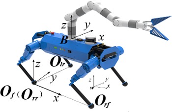
The coordinate frames of the HIboT.

As shown in Fig. 1, we construct the foot plane coordinate system of { O f }, treated O rr O rf as the x-axis, which is
 \begin{equation} \boldsymbol{n}_{f}=\frac{\boldsymbol{p}_{rf}-\boldsymbol{p}_{rr}}{\left\| \boldsymbol{p}_{rf}-\boldsymbol{p}_{rr}\right\| } \end{equation}
The z-axis is the normal vector of the foot plane constructed by the supporting foot:
 \begin{equation} \boldsymbol{a}_{f}=\frac{\boldsymbol{n}_{f}\times \left(\boldsymbol{p}_{lr}-\boldsymbol{p}_{rr}\right)}{\left\| \boldsymbol{n}_{f}\times \left(\boldsymbol{p}_{lr}-\boldsymbol{p}_{rr}\right)\right\| } \end{equation}
where the symbol × means cross product. So the y-axis is
 \begin{equation} \boldsymbol{o}_{f}=\boldsymbol{a}_{f}\times \boldsymbol{n}_{f} \end{equation}
The above formulas can be expressed both in the base coordinate frame and the world coordinate frame. Therefore, the pose transformation matrix from the world coordinate frame to the foot frame is
 \begin{equation} {}^{w}{\boldsymbol{T}}{_{f}^{}}=\left[\begin{array}{c@{\quad}c@{\quad}c@{\quad}c} {}^{w}{\boldsymbol{n}}{_{f}^{}} & {}^{w}{\boldsymbol{o}}{_{f}^{}} & {}^{w}{\boldsymbol{a}}{_{f}^{}} & {}^{w}{\boldsymbol{p}}{_{rr}^{}}\\ \\[-8pt] 0 & 0 & 0 & 1 \end{array}\right] \end{equation}
The pose transformation matrix from the base coordinate frame to the world coordinate frame is
 \begin{equation} {}^{b}{\boldsymbol{T}}{_{f}^{}}=\left[\begin{array}{c@{\quad}c@{\quad}c@{\quad}c} {}^{b}{\boldsymbol{n}}{_{f}^{}} & {}^{b}{\boldsymbol{o}}{_{f}^{}} & {}^{b}{\boldsymbol{a}}{_{f}^{}} & {}^{b}{\boldsymbol{p}}{_{rr}^{}}\\ \\[-8pt] 0 & 0 & 0 & 1 \end{array}\right] \end{equation}
Then the forward position kinematics transformation matrix from the world frame to the base frame is obtained:
 \begin{equation} {}^{w}{\boldsymbol{T}}{_{b}^{}}={}^{w}{\boldsymbol{T}}{_{f}^{}}{}^{f}{\boldsymbol{T}}{_{b}^{}}={}^{w}{\boldsymbol{T}}{_{f}^{}}\left({}^{b}{\boldsymbol{T}}{_{f}^{}}\right)^{-1} \end{equation}
Therefore, the HIphanT LMS transformation matrix from the world coordinate frame to the robotic manipulation arm end effector is
 \begin{equation} {}^{w}{\boldsymbol{T}}{_{e}^{}}={}^{w}{\boldsymbol{T}}{_{f}^{}}\left(^{b}\boldsymbol{T}_{f}\right)^{-1}\cdot {}^{b}{\boldsymbol{T}}{_{e}^{}} \end{equation}
where
 ${}^{b}{\boldsymbol{T}}{_{e}^{}}$
is the transformation matrix from the base coordinate frame to the robotic manipulator end effector, which is
 \begin{equation} {}^{b}{\boldsymbol{T}}{_{e}^{}}=f\text{kine}\left(\boldsymbol{q}_{\text{arm}}\right) \end{equation}
where
 $\boldsymbol{q}_{\text{arm}}$
expresses the arm joint angles.
The inverse kinematics is relatively more straightforward. If only the pose of the end effector and foot position are determined, the final solution still has infinite solutions. We need to add additional constraints to solve, for example, the pose of the base. It will be easier to solve. The arm joint is
 \begin{equation} \boldsymbol{q}_{\text{arm}}=i\text{kine}\left({}^{b}{\boldsymbol{T}}{_{e}^{}}\right) \end{equation}
The fi leg joint is
 \begin{equation} \boldsymbol{q}_{fi}=i\text{kine}\left({}^{b}{\boldsymbol{T}}{_{fi}^{}}\right) \end{equation}
Although there will still be multiple solutions in calculating the formula (10) and (11), the only solution we need can be chosen by a reasonable configuration judgment.
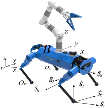
The screw coordinates frame of HIphanT LMS.

2.2. Kinematics in velocity level
There are 18 joints in HIphanT LMS. This system belongs to a super redundant mechanical system. Obstacle avoidance and stability planning by controlling the system’s center of mass should be considered while operating. So it is necessary to carry out the velocity kinematics analysis.
The velocity forward kinematics analysis is based on the homogeneous transformation matrix of the base relative to the world coordinate frame
 ${}^{w}\boldsymbol{T}_{b}$
, and the angle and speed of each joint to solve the speed of the end effector of the robotic manipulation arm relative to the world. Since the foot contact point does not change, we can model the forward velocity kinematics through the screw of the parallel mechanism of the HIboT.
We only constrain contact foot position, not its attitude. Take the right front leg as an example. As shown in Fig. 2, three screws are added at the foot as
 . These three screws are perpendicular to each other, and the intersection is at the origin of the rf foot coordinate frame
 $O_{rf}$
. The direction of
 is parallel to the main axis of the world coordinate frame. These three joints are passive. There are three active joints along the positive direction of the z-axis of the three joints of the rf leg. We first calculate the formula expression of the direction of the three active joints in the world coordinate frame. Formula (7) presents the homogenous transform matrix of the base relative to the world coordinate frame. Combined with the specific joint forward kinematics of each leg, the transformation matrix of the corresponding joint direction vector relative to the world frame can be obtained as:
 \begin{equation} {}^{w}{\boldsymbol{T}}{_{i}^{}}={}^{w}{\boldsymbol{T}}{_{B}^{}}\cdot ^{B}\boldsymbol{T}_{i}=\left[\begin{array}{c@{\quad}c@{\quad}c@{\quad}c} ^{w}\boldsymbol{n}_{i} & ^{w}\boldsymbol{o}_{i} & ^{w}\boldsymbol{a}_{i} & ^{w}\boldsymbol{p}_{i}\\ \\[-8pt] 0 & 0 & 0 & 1 \end{array}\right] \end{equation}
where
 $^{B}\boldsymbol{T}_{i}$
is the transformation matrix of the i-th joint frame relative to the base frame.
So the first joint frame relative to the world frame is
 \begin{equation} {}^{w}{\boldsymbol{T}}{_{1}^{}}={}^{w}{\boldsymbol{T}}{_{B}^{}}\cdot ^{B}\boldsymbol{T}_{1}=\left[\begin{array}{c@{\quad}c@{\quad}c@{\quad}c} ^{w}\boldsymbol{n}_{1} & ^{w}\boldsymbol{o}_{1} & ^{w}\boldsymbol{a}_{1} & ^{w}\boldsymbol{p}_{1}\\ \\[-8pt] 0 & 0 & 0 & 1 \end{array}\right] \end{equation}
The second joint frame relative to the world frame is
 \begin{equation} {}^{w}{\boldsymbol{T}}{_{2}^{}}={}^{w}{\boldsymbol{T}}{_{B}^{}}\cdot ^{B}\boldsymbol{T}_{2}=\left[\begin{array}{c@{\quad}c@{\quad}c@{\quad}c} ^{w}\boldsymbol{n}_{2} & ^{w}\boldsymbol{o}_{2} & ^{w}\boldsymbol{a}_{2} & ^{w}\boldsymbol{p}_{2}\\ \\[-8pt] 0 & 0 & 0 & 1 \end{array}\right] \end{equation}
The third joint frame relative to the world frame is
 \begin{equation} {}^{w}{\boldsymbol{T}}{_{3}^{}}={}^{w}{\boldsymbol{T}}{_{B}^{}}\cdot ^{B}\boldsymbol{T}_{3}=\left[\begin{array}{c@{\quad}c@{\quad}c@{\quad}c} ^{w}\boldsymbol{n}_{3} & ^{w}\boldsymbol{o}_{3} & ^{w}\boldsymbol{a}_{3} & ^{w}\boldsymbol{p}_{3}\\ \\[-8pt] 0 & 0 & 0 & 1 \end{array}\right] \end{equation}
The position direction of the second and the third joints are parallel to each other in space:
 \begin{equation} ^{w}\boldsymbol{a}_{2}={}^{w}{\boldsymbol{a}}{_{3}^{}} \end{equation}
The six screw frames of the right front leg are as follows:


where the formulas (17)–(22) are expressed in the world coordinate frame. Representing this screws system in the matrix form:

where
 are the active joints’ screws and
 are the passive joints’ screws. The reciprocal theory can calculate the active joints’ reciprocal screws
 . That is, the reciprocal screw
 of the j-th joint is reciprocal to the other screws
J
j
besides the screw
 . Where
J
j
is

The solution is solved by the null space of the screw matrix
J
j
to get
 , which is
 to the active joint. The matrix constructed by
 is the projection matrix
A
rf
, which is

where
 \begin{equation} \boldsymbol{E} = \left[\begin{array}{c@{\quad}c} \mathbf{0}_{\mathbf{3}} & \boldsymbol{I}_{\mathbf{3}}\\ \\[-8pt] \boldsymbol{I}_{\mathbf{3}} & \mathbf{0}_{\mathbf{3}} \end{array}\right] \end{equation}
Or matrix A rf can be expressed as:

The final projection matrix A , founded by all the support legs is

where n is the number of the support leg.
The inverse solution of the joint angular velocity and the base velocity is
 \begin{equation}\dot{\boldsymbol{q}}_{\text{leg}}=AEv_{\text{base}}\end{equation}
where
 $\dot{\boldsymbol{q}}$
leg is the angular velocity of the active joint of the support legs.
 $\boldsymbol{v}_{\text{base}}$
is the base velocity.
Conversely, the forward solution for the active joint relative to the base is
 \begin{equation} \boldsymbol{v}_{\text{base}}=\boldsymbol{J}\left(\boldsymbol{AEJ}\right)^{-1}\dot{\boldsymbol{q}}_{\text{leg}} \end{equation}
where J is one set basis of the free movement space of the platform’s base. For the three-leg support or four-leg support situation,
 \begin{equation} \boldsymbol{J}=\boldsymbol{I}_{6} \end{equation}
Besides, if the
 $(\boldsymbol{AEJ})$
is irreversible, use the pseudo-inverse to calculate.
The speed of the robotic arm relative to the base is
 \begin{equation} ^{b}\boldsymbol{v}_{e}=\boldsymbol{J}_{\text{arm}}\dot{\boldsymbol{q}}_{\text{arm}} \end{equation}
where
J
arm is the jacobian matrix of the robotic manipulation arm.
 $^{b}\boldsymbol{v}_{e}$
is the end effector’s velocity and
 $\dot{\boldsymbol{q}}$
arm is the angular velocity of the robotic arm joints.
So the velocity of the end effector relative to the world coordinate frame is
 \begin{align} \left[\begin{array}{c} \boldsymbol{v}_{e}\\ \\[-8pt] \boldsymbol{\omega }_{e} \end{array}\right] & =\left[\begin{array}{c} \boldsymbol{v}_{\text{base}}+^{w}{\boldsymbol{R}_{b}}^{b}\boldsymbol{v}_{\text{arm}}+\boldsymbol{w}_{\text{base}}\times ^{w}\boldsymbol{R}_{b}{\overline{{^{b}\boldsymbol{r}_{\text{arm}}}}}\\ \\[-8pt] \boldsymbol{w}_{\text{base}}+^{w}\boldsymbol{R}_{b}\boldsymbol{w}_{\text{arm}} \end{array}\right]\nonumber\\[3pt] & =\left[\begin{array}{c@{\quad}c} \boldsymbol{J}_{v\_ \text{leg}}\left(\boldsymbol{AE}\boldsymbol{J}_{\text{leg}}\right)^{-1}-\left(\left(^{w}\boldsymbol{R}_{b}{\overline{{^{b}\boldsymbol{r}_{\text{arm}}}}}\right)^{\times }\left(\boldsymbol{J}_{w\_{\text{leg}}}\left(\boldsymbol{AE}\boldsymbol{J}_{\text{leg}}\right)^{-1}\right)\right) & {}^{w}{\boldsymbol{R}}{_{b}^{}}\boldsymbol{J}_{v\_ \text{arm}}\\ \\[-8pt] \boldsymbol{J}_{w\_{\text{leg}}}\left(\boldsymbol{AE}\boldsymbol{J}_{\text{leg}}\right)^{-1} & ^{w}\boldsymbol{R}_{b}\boldsymbol{J}_{w\_ \text{arm}} \end{array}\right]\left[\begin{array}{c} \dot{\boldsymbol{q}}_{\text{leg}}\\ \\[-8pt] \dot{\boldsymbol{q}}_{\text{arm}} \end{array}\right] \end{align}
where
 $\boldsymbol{J}_{v\_ \text{leg}}$
and
 $\boldsymbol{J}_{w\_ \text{leg}}$
are the linear and angular velocities of Jacobian matrix of the base relative to the world frame,
 $\boldsymbol{J}_{v\_ \text{arm}}$
and
 $\boldsymbol{J}_{w\_ \text{arm}}$
are the linear and angular velocities of Jacobian matrix of the end effector relative to the base coordinate frame, and
 ${}^{b}\boldsymbol{r}_{\text{arm}}$
is the vector distance of the end effector relative to the base.
If only considering the floating base manipulator, the system velocity kinematics is
 \begin{equation} \begin{array}{c@{\quad}c} \left[\begin{array}{c} \boldsymbol{v}_{e}\\ \\[-8pt] \boldsymbol{\omega }_{e} \end{array}\right] & =\left[\begin{array}{c} \boldsymbol{v}_{\text{base}}+^{w}{\boldsymbol{R}_{b}}^{b}\boldsymbol{v}_{\text{arm}}+\boldsymbol{w}_{\text{base}}\times ^{w}\boldsymbol{R}_{b}{\overline{{^{b}\boldsymbol{r}_{\text{arm}}}}}\\ \\[-8pt] \boldsymbol{w}_{\text{base}}+^{w}\boldsymbol{R}_{b}w_{\text{arm}} \end{array}\right]\\ \\[-8pt] & =\left[\begin{array}{c} \boldsymbol{v}_{\text{base}}+{}^{w}{\boldsymbol{R}}{_{b}^{}}\boldsymbol{J}_{v\_ \text{arm}}\cdot \dot{\boldsymbol{q}}_{\text{arm}}-\left({}^{w}{\boldsymbol{R}}{_{b}^{}}{\overline{{^{b}\boldsymbol{r}_{\text{arm}}}}}\right)^{\times }\boldsymbol{w}_{\text{base}}\\ \\[-8pt] \boldsymbol{w}_{\text{base}}+^{w}\boldsymbol{R}_{b}\boldsymbol{J}_{w\_ \text{arm}}\cdot \dot{\boldsymbol{q}}_{\text{arm}} \end{array}\right]\\ \\[-8pt] & =\left[\begin{array}{c@{\quad}c@{\quad}c} \mathbf{\textit{I}}_{3} & -\left({}^{w}{\boldsymbol{R}}{_{b}^{}}{\overline{{^{b}\boldsymbol{r}_{\text{arm}}}}}\right)^{\times } & {}^{w}{\boldsymbol{R}}{_{b}^{}}\boldsymbol{J}_{v\_ \text{arm}}\\ \\[-8pt] \mathbf{0}_{3} & \mathbf{\textit{I}}_{3} & ^{w}\boldsymbol{R}_{b}\boldsymbol{J}_{w\_ \text{arm}} \end{array}\right]\left[\begin{array}{c} \boldsymbol{v}_{\text{base}}\\ \\[-8pt] \boldsymbol{w}_{\text{base}}\\ \\[-8pt] \dot{\boldsymbol{q}}_{\text{arm}} \end{array}\right] \end{array} \end{equation}
where
 $\boldsymbol{v}_{\text{base}}$
and
 $\boldsymbol{w}_{\text{base}}$
are the linear and angular velocities of the base, respectively.
3. Locomotion manipulation system trajectory planning method
3.1. The unified trajectory planning method
The HIPhanT LMS performs tasks such as opening doors and moving goods. Firstly, it is necessary to ensure that the overall manipulation process is stable by adjusting the system’s center of mass. Secondly, the operability index should increase to make the manipulation more flexible. Therefore, the most basic requirement is to ensure the LMS’s balanced state and manipulability without affecting the end effector’s movement. Since the HIphanT LMS has 18 DOFs, the trajectory of each joint can be solved from the null space projection.
From the formula (34), the base has six DOFs. We set the first three DOFs of the base coordinate frame as the translation joints along the world frame’s x-, y-, and z-axis. The last three joints are the revolutes joints that rotate around the world frame’s x-, y-, and z-axis. The forward solution of the kinematics relationship between the end effector and each joint is
 \begin{equation} \dot{\boldsymbol{x}}_{e}=\left[\begin{array}{c} \boldsymbol{v}_{e}\\ \\[-8pt] \boldsymbol{w}_{e} \end{array}\right]=\boldsymbol{J}\dot{\boldsymbol{q}} \end{equation}
where
 $\dot{\boldsymbol{x}}_{e}$
is the velocity of the end effector,
J
is the LMS jacobian, and
 $\dot{\boldsymbol{q}}$
is the joint angular velocity.
To increase the manipulability of the HIphanT LMS in a specific end effector position, we need to calculate the velocity of each joint by the null space projection method:
 \begin{equation} \dot{\boldsymbol{q}}=\boldsymbol{J}^{+}\dot{\boldsymbol{x}}+\left(\boldsymbol{I}-\boldsymbol{J}^{+}\boldsymbol{J}\right)\boldsymbol{\phi } \end{equation}
where
 $\boldsymbol{\phi }$
is desired joint velocity and
 $(\boldsymbol{I}-\boldsymbol{J}^{+}\boldsymbol{J})$
is the null space projection matrix,
 \begin{equation} \boldsymbol{J}^{+}=\boldsymbol{J}^{T}\left(\boldsymbol{J}\boldsymbol{J}^{T}\right)^{-1} \end{equation}
One of the main tasks of an LMS is to interact with environments. So manipulability is critical to the whole system. According to the definition of manipulability, which is
 \begin{equation} w\left(\boldsymbol{q}\right)=\sqrt{\det \left(\boldsymbol{J}\left(\boldsymbol{q}\right)\boldsymbol{J}\left(\boldsymbol{q}\right)^{{T}}\right)} \end{equation}
The manipulability is positively correlated with the root mean square of the eigenvalues of the jacobian matrix of the system. Thus, the joint velocity directions that can increase the manipulability under the current configuration are calculated:
 \begin{equation} \dot{q}_{i}=\dot{w}\left(q_{i}\right)=\frac{\partial w}{\partial q_{i}} \end{equation}
However, this only works when the end effector can move freely in space or each joint can work independently. When the end effector pose is not changed, each joint is not independent. In other words, since the movement of the current end effector is constrained, the rest of the joint angles will also be adjusted accordingly when one of the joint angles is changed. Thus, the formula (39) should be rewritten as:
 \begin{align} \dot{w}\left(q_{i}\right)&=f\left(q_{1}\left(q_{i}\right),q_{2}\left(q_{i}\right),\ldots,q_{i},\ldots,q_{12}\left(q_{i}\right)\right)\nonumber \\[3pt] &=\frac{\partial w}{\partial q_{1}}\cdot \frac{\partial q_{1}}{\partial q_{i}}+\ldots +\frac{\partial w}{\partial q_{i}}+\ldots +\frac{\partial w}{\partial q_{12}}\cdot \frac{\partial q_{12}}{\partial q_{i}} \end{align}
The analytic expression
 $\dot{w}(q_{i})$
cannot be expressed, so the formula (40) is solved by the numerical method. When the joint q
i
increases to
 $q_{i}+\Delta q$
in unit time,
 $\boldsymbol{\phi }$
is
 \begin{equation} \boldsymbol{\phi }=\left[0,\ldots,q_{i}+\Delta q,\ldots 0\right] \end{equation}
We calculate the other joint angle changes according to the formula (36),
 \begin{equation} {\boldsymbol{q}_{\boldsymbol{f}}}=\left[q_{1}+\Delta q_{1},\ldots,q_{i}+\Delta q_{i},\ldots,q_{12}+\Delta q_{12}\right] \end{equation}
So
 $\dot{w}(q_{i})$
is
 \begin{align} \dot{w}\left(q_{i}\right) & =\frac{w\left(q_{f}\right)-w\left(q\right)}{\Delta q_{1}}\cdot \frac{\Delta q_{1}}{\Delta q_{i}}+\ldots +\frac{w\left(q_{f}\right)-w\left(q\right)}{\Delta q_{i}}+\ldots +\frac{w\left(q_{f}\right)-w\left(q\right)}{\Delta q_{12}}\cdot \frac{\Delta q_{12}}{\Delta q_{i}} \nonumber\\[3pt] & =12\times \frac{w\left(q_{f}\right)-w\left(q\right)}{\Delta q_{i}} \end{align}
Making
 \begin{equation} \phi _{\,i}=\dot{w}\left(q_{i}\right) \end{equation}
After calculating all the joint angles by the formula (43), we obtain the joint velocity direction
 $\boldsymbol{\phi }$
that increases the manipulability of the HIphanT system:
 \begin{equation} \boldsymbol{\phi }=\left[\dot{w}\left(q_{1}\right),\ldots,\dot{w}\left(q_{12}\right)\right] \end{equation}
We can obtain the joint velocity by substituting formula (45) into formula (36).
3.2. Joint constraints
In addition to the manipulability requirements, another critical condition is that the system must be stable. For the three or four supporting leg situations, this requirement is equal to ensure the COM of the HIphanT LMS is within the support ranges. So the first two translational DOFs can effectively and quickly adjust the planning of the COM.
Let the mass of each joint is mi
, and the coordinate of the center of mass in the respective joint coordinate frame is
 $({}^{i}{x}{},{}^{i}{y}{},{}^{i}{z}{})$
. The coordinate of the center of mass in the world frame is
 $({}^{w}{x}{_{i}^{}},{}^{w}{y}{_{i}^{}},{}^{w}{z}{_{i}^{}})$
by the homogenous transformation of the formula (12):
 \begin{equation} {}^{w}{\overline{\boldsymbol{p}_{i}}}{}=\left[\begin{array}{c} {}^{w}{x}{_{i}^{}}\\ \\[-8pt] {}^{w}{y}{_{i}^{}}\\ \\[-8pt] {}^{w}{z}{_{i}^{}}\\ \\[-8pt] 1 \end{array}\right]={}^{w}{\boldsymbol{T}}{_{i}^{}}\left[\begin{array}{c} {}^{i}{x}{}\\ \\[-8pt] {}^{i}{y}{}\\ \\[-8pt] {}^{i}{z}{}\\ \\[-8pt] 1 \end{array}\right] \end{equation}
So the COM of the HIphanT LMS is
 \begin{equation} {}^{w}{\boldsymbol{p}}{_{\text{com}}^{}}=\frac{\sum _{i=1}^{18}\left({}^{w}{\boldsymbol{p}}{_{i}^{}}\cdot m_{j}\right)}{\sum _{i=1}^{18}m_{j}} \end{equation}
If it is within the support range,
 \begin{equation} \left\{\begin{array}{c} \dot{q}_{1}=p_{x}d_{x}\\ \\[-8pt] \dot{q}_{2}=p_{y}d_{y} \end{array}\right. \end{equation}
where
 $p_{x}, p_{y}$
are the proportional factors of the first joint, d
x
and d
y
are the distances between the COM and support range center in the x- and y-directions.
Therefore, we have completed the null space joint velocity-solving solution
 $\phi$
. By substituting into the formula (36), the final joint velocity is obtained. The base velocity
 $\boldsymbol{v}_{\text{base}}$
is
 \begin{equation} \boldsymbol{v}_{\text{base}}=\dot{\boldsymbol{q}}_{\left(1\,{:}\, 6\right)} \end{equation}
where
 $\dot{\boldsymbol{q}}$
(1:6) are the former six elements of the final joint velocity. From the formula (29), we have the joint velocity of the legs.
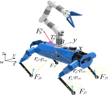
However, even the robot’s COM is within the support range, we cannot satisfy the contact foot not sliding assumption. It is necessary to constrain the corresponding contact force. As shown in Fig. 3, the desired force on the base is
 $(\boldsymbol{F}_{B}^{d},\boldsymbol{T}_{B}^{d})$
. This force is generated from the contact force
 $\boldsymbol{F}_{fi}$
and the moment of contact force relative to system COM. The contact force can be decomposed into support force
 $\boldsymbol{F}_{fi}^{n}$
and friction force
 $\boldsymbol{F}_{fi}^{t}$
. The support force is in the z-axis direction of the world frame. The friction is in the x/y axis of the world frame. So in the balance state, we have
 \begin{equation} \left[\begin{array}{c@{\quad}c@{\quad}c} \boldsymbol{I}_{3} & \ldots & \boldsymbol{I}_{3}\\ \\[-8pt] \left[\boldsymbol{r}_{f1}-\boldsymbol{p}_{\text{com}}\right]\times & \ldots & \left[\boldsymbol{r}_{f1}-\boldsymbol{p}_{\text{com}}\right]\times \end{array}\right]_{6\times 3n}\left[\begin{array}{c} \boldsymbol{F}_{f1}\\ \\[-8pt] \vdots \\ \\[-8pt] \boldsymbol{F}_{fn} \end{array}\right]_{3n\times 1}=\left[\begin{array}{c} \boldsymbol{F}_{B}^{d}\\ \\[-8pt] \boldsymbol{T}_{B}^{d} \end{array}\right] \end{equation}
where
 $\boldsymbol{r}_{fi}$
is the i-th foot contact position in the world frame,
 $\boldsymbol{p}_{\text{com}}$
is the COM of the system, obtained from formula (47), and n is the contact foot number.
The system force analysis diagram.

The desired base force is calculated by the single-body dynamic algorithms, which is
 \begin{equation} \left[\begin{array}{c} \boldsymbol{F}_{B}^{d}\\ \\[-8pt] \boldsymbol{T}_{B}^{d} \end{array}\right]=\left[\begin{array}{c} m\left(\ddot{\boldsymbol{p}}_{\mathrm{com}}+\boldsymbol{g}\right)\\ \\[-8pt] \boldsymbol{I}_{B}\dot{\boldsymbol{\omega }}_{B} \end{array}\right]_{6\times 1} \end{equation}
where
 $m$
is the system total mass,
 $\,\ddot{\boldsymbol{p}}$
com is the COM’s linear acceleration,
 $\boldsymbol{I}_{B}$
is the system’s inertial matrix, and
 $\dot{\boldsymbol{\omega }}$
B is the base angular acceleration.
However, there are situations where multiple legs support the robot, so the solution of contact force
 $\boldsymbol{F}_{fi}$
may be infinite. Under the contact foot not sliding assumption, the contact force should be within the friction cone. We use quadratic programming to solve this problem:
 \begin{equation} \begin{array}{c} \min \boldsymbol{F}_{\text{err}}=\left(\boldsymbol{Ax}-\boldsymbol{b}\right)^{T}\boldsymbol{S}\left(\boldsymbol{Ax}-\boldsymbol{b}\right)\\ \\[-8pt] \text{subject to}\colon \left\{\begin{array}{c} \boldsymbol{F}_{fi}^{n}\geq \boldsymbol{F}_{\min }\\ \\[-8pt] -\mu \boldsymbol{F}_{fi}^{n}\leq \boldsymbol{F}_{fi}^{t}\leq \mu \boldsymbol{F}_{fi}^{n} \end{array}\right. \end{array} \end{equation}
where x is the contact force, b is the desired base force, S is the selection matrix, and A is the contact force distribution matrix in the formula (50).
After solving the formula (52), we check the value of
 $\min \boldsymbol{F}_{\text{err}}$
. We believe the contact force is solved if this value is smaller than a threshold. The corresponding COM of the system is reachable. Otherwise, we should plan the system trajectory again.
4. Simulation and experiments
4.1. Experimental setup
The HIphanT system’s overall mass is 45 kg, with 35 kg from the HIboT. The HIboT torso size is 1.00 m × 0.50 m. It loads with rich sensors such as inertial measurement units (IMU), lidar sensors, visual cameras, which can detect the environment and calculate the system’s pose. The HIboT has four three DOF serial legs with 0.6 m length. The second and third joints are arranged in an offset manner so that the work range angle of the third joint exceeds 360°, which significantly improves the flexibility of the HIphanT LMS movement. The lower legs are constructed of carbon fiber tubes to reduce the legs’ inertia. The foot is a balloon structure. The air pressure of the balloon judges the foot contact state. Besides, the balloon structure filled with air can effectively reduce the impact during the walking process.
In terms of the joint design, all 12 joints are modular. To minimize the transmission loss and improve the response time of the joints, a planetary reducer ratio of 18.6:1 is used. The motors are from Allied Motion Company’s MF series motor, which can provide an 18-Nm stalled torque. The parameters of joints are as follows. The joint mass is 2.3 kg with stalled torque 80 Nm. Each joint has an absolute position encoder at the motor end to record the joint position and the rotation speed of the motor. The motor driver is from ELMO. It can calculate the motor torque through the torque current coefficient. After the joint friction force calibration, the joint output torque can be estimated and the joint torque control can be performed.
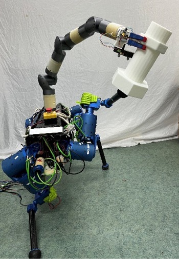
The robotic manipulation arm is also self-developed. It is described in detail in reference [Reference Wu, Chen and Xu25]. Finally, connect the HIT-Armc and HIboT through the bolt to the HIphanT LMS, as shown in Fig. 4. All the programs run on ROS based on the Intel NUC [Reference Peng, Haibin, Lei and Wenfu26].
HIphanT locomotion manipulation system.

4.2. Static end point control experiment
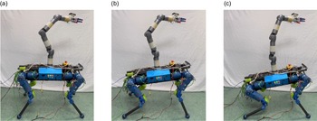
This experiment verifies that the end effector remains unchanged by adjusting the joint angle, increasing the HIphanT LMS manipulation. Figure 5 shows this adjustment process by the initial, middle, and final configuration of the HIphanT.
Static end effector control experiment. (a) Initial configuration. (b) Middle configuration. (c) Final configuration.

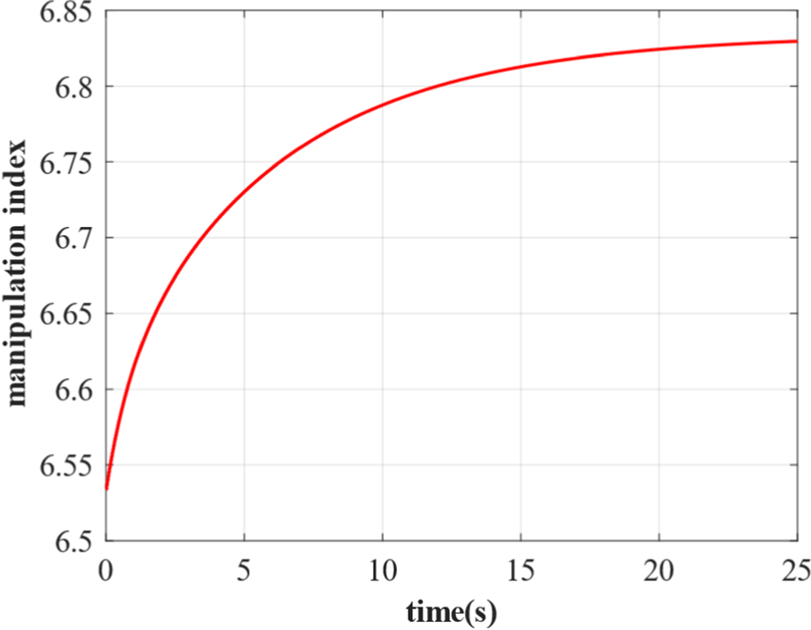
Figure 5a shows the initial configuration of the HIphanT LMS. The manipulability is 6.54. All joints are in the middle range of the joint working space. However, after the adjustment process, as shown in Fig. 5b, the final manipulability reaches 6.835. The manipulability curve is shown in Fig. 6.
Manipulability curve.

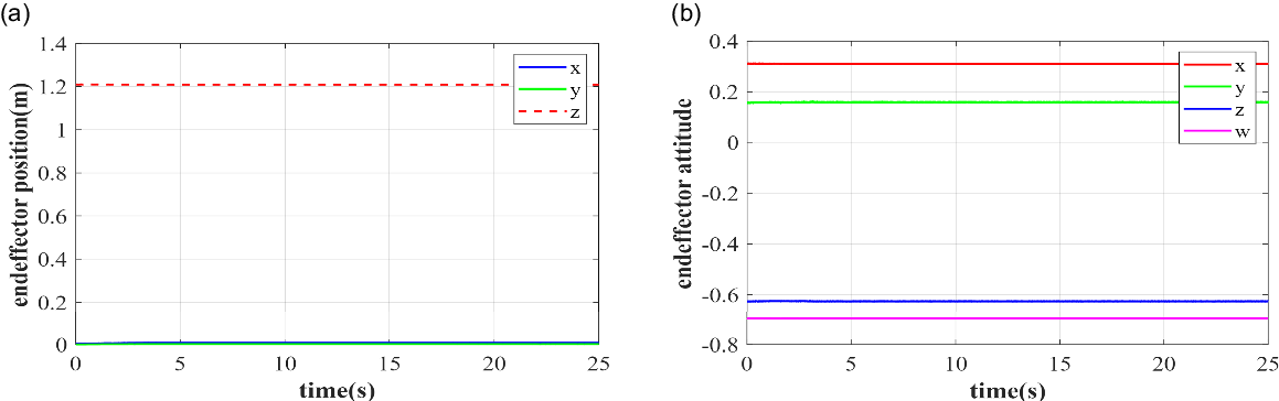
The OptiTracker V120 TRIO system collects the pose of the end effector by three independent markers placed nonlinear on the end effector. These noncollinear markers form a rigid body. Since the rigid body and the end effector are rigidly coupled, the pose change of the end effector can be obtained by collecting the pose change of the rigid body. The pose curve is shown in Fig. 7. Figure 7a is the end effector position curves. Figure 7b is the end effector pose, expressed by the unit quaternion.
The pose curve of the LMS end effector. (a) End effector position curves. (b) End effector attitude curves.

Fit the trajectory curves of the end effector by the expression:
 \begin{equation} y=\text{const}\!\left(t\right) \end{equation}
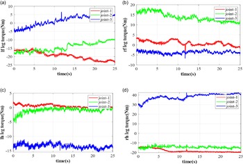
where t is the time. const(t) returns a constant value, which is the average value of the corresponding trajectory. The sums of the squared difference of pose trajectories are in the order of 10e-5. The leg torques are shown in Fig. 8.
Leg torques. (a) Left front leg joints torques. (b) Right front leg joints torques. (c) Left hind front leg joints torques. (d) Right hind leg joints torques.

This experiment verifies the effectiveness of the static end point control algorithm.
4.3. Linear motion experiment
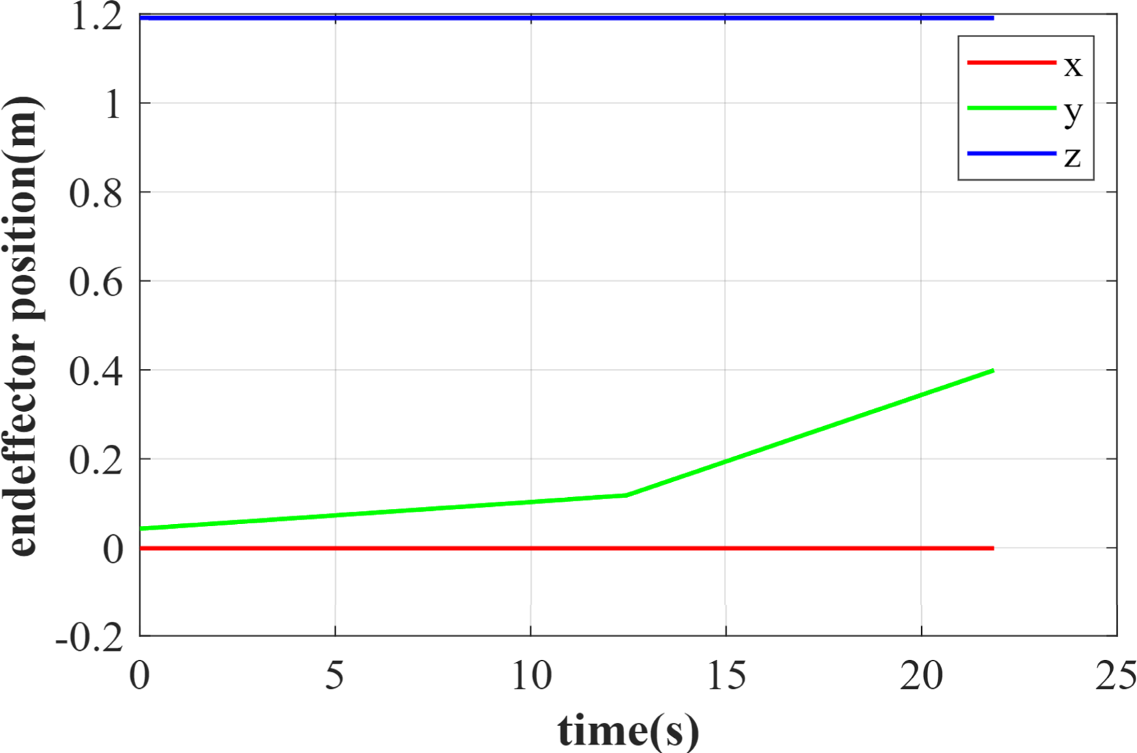
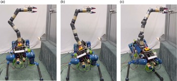
In this experiment, the end effector of the HIphanT LMS moves linearly along the positive y-axis for 0.4 m in the world frame. The position of the other two axes remains unchanged. The trajectory curves are shown in Fig. 9. During the motion planning, the manipulability and COM position of the LMS are considered simultaneously. At the start time, the COM position is located near the center of the support area. The manipulability is “far away” from the optimal manipulability. So manipulability significantly affects the joint angles’ motion planning, which causes a considerable joint angular velocity. Since the movement of the early state, before 12.5 s, is the manipulability increasing time, we set a lower movement speed to reduce the joint speed. Figure 10 shows the experiment process. Figure 10a is the initial configuration, and b and c are the middle and final configurations, respectively.
End effector position curves.

Static end effector control experiment. (a) Initial configuration. (b) Middle configuration. (c) Final configuration.

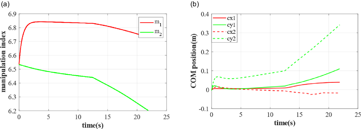
In Fig. 11a, the m1 curve is the manipulability curve obtained by both COM position and system manipulability optimization. The m2 curve is obtained only by considering the COM position optimization. By comparison, it can be found that the manipulation is effectively improved by 8.87%, which makes the HIphanT LMS more flexible. Figure 11b is the COM position curve. The cx represents x coordinates of the COM position and cy represents y coordinates. The cx1 and cy1 curves are the COM position trajectories obtained by simultaneously performing both the COM position and manipulability optimization. The curves cx2 and cy2 are obtained only considering the manipulability optimization. Since the end effector moves in the positive y direction in the world frame, the COM position moves in the same direction as expected. After the optimization, the distance between the optimized COM and the support area center is 0.1175 m, while the unoptimized distance is 0.3427 m, significantly exceeding the safety support area.
Manipulability curves and COM position. (a) Manipulability curves. (b) COM position curves.

Therefore, the joint angles obtained by simultaneously performing the manipulability and COM position optimization can improve the system’s manipulation capability and stability margin. This experiment proves the effectiveness of the optimization algorithm.
5. Conclusion
This paper presents two main contributions: legged LMS unified kinematics modeling in position and velocity level and a unified trajectory planning method based on manipulability and stability. The unified kinematics model in position and velocity level of the legged LMS is established because the support foot does not slide when the system arrives at a specified position. Therefore, the support foot can be regarded as a spherical hinge, and the legged platform is a parallel mechanism. Through unified modeling, we deduce the forward and inverse kinematics relationship of the end effector of the robotic manipulation arm and the joint angles. The trajectory planning method is based on the system’s manipulability and stability. We can achieve a relatively high manipulability when the end effector remains unchanged in the world coordinate frame through the null space projections. The stability requirement also influences the trajectory planning process, and the stability margin increases as much as possible. All contributions are validated on the LMS HIphanT.
In the future, we will carry out motion planning from the perspective of the overall movement. We need to be able to realize the movement of the locomotion platform and the manipulation of the robotic arm simultaneously. Besides, we only construct the kinematics model of the LMS HIphanT, and in the next step, we will analyze the dynamics model of the whole system.
Author contributions
All authors contributed to the study’s conception and design. The research concept was from Wenfu Xu and Peng Kang. Material preparation, data collection, and analysis were performed by Peng Kang and Haibin Meng. Peng Kang wrote the first draft of the manuscript, and all authors commented on previous versions. All authors read and approved the final manuscript.
Financial support
This work is supported by Shenzhen excellent scientific and technological innovation talent training project (Grant No. RCJC20200714114436040) and the Basic Research Program of Shenzhen (JCYJ20220818102415034, JSGG20200103103401723).
Conflicts of interest
The authors declare no conflicts of interest exist.
Ethical approval
Not applicable.