1 Introduction
Particle-laden turbulent flows are ubiquitous and challenging due to the multi-scale physics involved (see der Hoef et al. Reference der Hoef, Annald, Deen and Kuipers2008). Turbulence has an important role in the motion of particles. The transport, entrainment and redeposition (Soldati & Marchioli Reference Soldati and Marchioli2009) of solid particles, such as coal dust, are crucial in determining the overall efficiency of energy plants (Buhre et al. Reference Buhre, Elliott, Sheng, Gupta and Wall2005). In automotive applications, spray formation (Marmottant & Villermaux Reference Marmottant and Villermaux2004) and the ensuing fuel jets (Jenny, Roekaerts & Beishuizen Reference Jenny, Roekaerts and Beishuizen2012) have an impact on the overall efficiency of combustion. Physical phenomena such as inter-particle collisions (Post & Abraham Reference Post and Abraham2002; Wang et al. Reference Wang, Rosa, Gao, He and Jin2009) and turbulent modification (Balachandar & Eaton Reference Balachandar and Eaton2010) play an important role. In many applications, the multi-scale nature of the phenomena involved calls for modelling both the fluid turbulence and the particle motion; see Meyer (Reference Meyer2012) and Peirano et al. (Reference Peirano, Chibbaro, Pozorski and Minier2006) for modelling strategies in Reynolds-averaged Navier–Stokes equations and Marchioli (Reference Marchioli2017) and Innocenti, Marchioli & Chibbaro (Reference Innocenti, Marchioli and Chibbaro2016) in large-eddy simulation.
In the context of particle-laden turbulent flow, many studies have been conducted in the one-way coupling regime (see Elghobashi (Reference Elghobashi1994) for a discussion of the different regimes of coupling between fluid and particles), both from an experimental point of view (see e.g. Kostinski & Shaw Reference Kostinski and Shaw2001; Eidelman et al. Reference Eidelman, Elperin, Kleeorin, Hazak, Rogachevskii, Sadot and Sapir-Katiraie2009; Lau & Nathan Reference Lau and Nathan2016) and from a numerical point of view (see e.g. Marchioli & Soldati Reference Marchioli and Soldati2002; Goto & Vassilicos Reference Goto and Vassilicos2006; Bec et al. Reference Bec, Biferale, Cencini, Lanotte, Musacchio and Toschi2007; Toschi & Bodenschatz Reference Toschi and Bodenschatz2009; Battista et al. Reference Battista, Picano, Troiani and Casciola2011; Picano et al. Reference Picano, Battista, Troiani and Casciola2011; Sardina et al. Reference Sardina, Schlatter, Picano, Casciola, Brandt and Henningson2012b ). On the other hand, the two-way coupling regime, where the fluid–particle momentum exchange is significant, is still being thoroughly investigated and some open questions need to be addressed. The first one is related to the numerical technique employed to model a reliable fluid–particle interaction. The second is related to the physics and deals with the particle dynamics, with the particle spatial distribution and, most importantly, with the turbulence modulation.
In the literature, various techniques are used to model the fluid–particle interaction. The approaches mostly depend on the typical size of the particle, e.g. the diameter
 $d_{p}$
, that has to be compared with the characteristic length scales of the turbulent flow (see e.g. the recent review paper by Elghobashi (Reference Elghobashi2019)). The conceptually simplest approach is to resolve the particle boundary on the computational grid and to enforce no-slip conditions on each particle boundary (particle-resolved simulation). This technique has recently become viable due to ever-increasing computing resources. Among many, the immersed boundary technique (Uhlmann Reference Uhlmann2005; Breugem Reference Breugem2012) is employed to simulate suspensions under different conditions, for example in sedimentation problems (Fornari et al.
Reference Fornari, Brandt, Chaudhuri, Lopez, Mitra and Picano2016a
; Fornari, Picano & Brandt Reference Fornari, Picano and Brandt2016b
) or dense suspensions (Costa et al.
Reference Costa, Picano, Brandt and Breugem2018). Given the tremendous computational cost, such simulations can currently only tackle problems in simplified geometries where the scale of the particle is roughly 10 times larger than the dissipative scale of the turbulent flow and the choice of density ratio is limited.
In many applications, the typical particle diameter is comparable to, or even smaller than, the dissipative scale and the density ratio is relatively large. In these conditions, it is unaffordable to carry out particle-resolved simulations. Being small, the particles are modelled as material points which behave as concentrated momentum sources/sinks for the fluid via the hydrodynamic drag that the (small) particles experience along their trajectories.
In wall-bounded turbulent flows, the particles segregate towards the wall (Caporaloni et al. Reference Caporaloni, Tampieri, Trombetti and Vittori1975; Young & Leeming Reference Young and Leeming1997). This phenomenon is known as turbophoresis and is relevant since the particles close to the wall affect the turbulence in the buffer region where the production of turbulent kinetic energy occurs together with the generation of vortical structures; see Dritselis & Vlachos (Reference Dritselis and Vlachos2008, Reference Dritselis and Vlachos2011), Bijlard et al. (Reference Bijlard, Oliemans, Portela and Ooms2010) and Richter & Sullivan (Reference Richter and Sullivan2014) for an analysis of the topological modification of the structures in the buffer region.
An important issue in wall-bounded turbulent flows is whether the dispersed phase feedback produces an overall increase or decrease of friction and whether the turbulent fluctuations are augmented or reduced by the particles. Zhao, Andersson & Gillissen (Reference Zhao, Andersson and Gillissen2010, Reference Zhao, Andersson and Gillissen2013) found a reduction of the friction, i.e. the flow rate in the presence of particles is augmented with respect to the flow rate in the absence of particles for the same pressure gradient that drives the turbulent channel flow. Picciotto et al. (Reference Picciotto, Giusti, Marchioli and Soldati2006), Li, Luo & Fan (Reference Li, Luo and Fan2016a ) and Li et al. (Reference Li, Wei, Luo and Fan2016b ) considered the turbulence modulation in a boundary layer, showing an increase in the skin friction coefficient at the wall. Li et al. (Reference Li, McLaughlin, Kontomaris and Portela2001) reported that the overall drag might increase or decrease depending on the mass loading of the suspension and the particle Stokes number. Lee & Lee (Reference Lee and Lee2015) found an overall increase of the turbulent fluctuations for relatively small particles, and a decrease of the turbulent fluctuations for large particles. In contrast, Pan & Banerjee (Reference Pan and Banerjee1997) found an overall increase in drag in a channel flow.
All the simulations mentioned above exploit the classical particle in cell (PIC) approach introduced by Crowe, Sharma & Stock (Reference Crowe, Sharma and Stock1977), except for Pan & Banerjee (Reference Pan and Banerjee1997) who employed an alternative inter-phase momentum coupling based on the solution of a truncated steady Stokes flow for the disturbance flow produced by the particles. Simulations using the PIC approach have been performed also in pipe flow (see e.g. the direct numerical simulation by Rani, Winkler & Vanka (Reference Rani, Winkler and Vanka2004) and Vreman (Reference Vreman2007) and the large-eddy simulation by Yamamoto & Okawa (Reference Yamamoto and Okawa2010)). Recently, the effect of wall roughness has been discussed by Vreman (Reference Vreman2015) and De Marchis & Milici (Reference De Marchis and Milici2016).
From the experimental point of view, the motion, deposition, entrainment, spatial distribution and velocity profiles of the particles in a turbulent boundary layer have been addressed by Kaftori, Hetsroni & Banerjee (Reference Kaftori, Hetsroni and Banerjee1995a ,Reference Kaftori, Hetsroni and Banerjee b ) and Kaftori, Hetsroni & Banerjee (Reference Kaftori, Hetsroni and Banerjee1998). The fluid velocity profiles show larger gradients close to the wall (drag increasing) and the turbulent velocity fluctuations are increased in the near-wall region. These modifications are associated with an increase in wall shear stress. Similar results are found in the experiments by Righetti & Romano (Reference Righetti and Romano2004), Wu et al. (Reference Wu, Wang, Liu, Li, Zhang and Zheng2006) and Li et al. (Reference Li, Wang, Liu, Chen and Zheng2012). No substantial modification of the mean velocity profile has been reported by Kulick, Fessler & Eaton (Reference Kulick, Fessler and Eaton1994) where only turbulent fluctuations are depleted across the channel. In the geometry of the pipe, Tsuji, Morikawa & Shiomi (Reference Tsuji, Morikawa and Shiomi1984) show an increase in wall shear stress as well as Hadinoto et al. (Reference Hadinoto, Jones, Yurteri and Curtis2005). See also other experiments by Ljus, Johansson & Almstedt (Reference Ljus, Johansson and Almstedt2002), Caraman, Borée & Simonin (Reference Caraman, Borée and Simonin2003) and Borée & Caraman (Reference Borée and Caraman2005).
In the numerical simulations discussed, the inter-phase momentum coupling is mainly achieved using the PIC approach. Even though the approach is rather simple, it suffers from several drawbacks. Firstly, the back-reaction field, which can be constructed given the configuration of the suspension, is grid-dependent (Gualtieri et al. Reference Gualtieri, Picano, Sardina and Casciola2013). Secondly, the solution depends on how many particles per computational cell are available (see Boivin, Simonin & Squires (Reference Boivin, Simonin and Squires1998), Gualtieri et al. (Reference Gualtieri, Picano, Sardina and Casciola2013) and the general discussion by Balachandar & Eaton (Reference Balachandar and Eaton2010)). The unphysical constraint on the number of particles per cell poses several limitations on the range of the dimensionless parameters (Stokes number, mass loading, particle-to-fluid density ratio and Reynolds number) that can be explored in the simulations (see the conclusion of Gualtieri et al. (Reference Gualtieri, Picano, Sardina and Casciola2015)). A further issue concerns the model required to compute the hydrodynamic force on each particle. In the simple model of Stokes drag, the fluid velocity at the particle position must be correctly interpreted as the background fluid velocity, i.e. as the fluid velocity in the absence of the disturbance flow produced by the specific particle under consideration. Unfortunately, in two-way coupled simulations, the unperturbed flow is unavailable unless specific techniques are exploited to remove the particle self-disturbance (see e.g. Horwitz & Mani (Reference Horwitz and Mani2016, Reference Horwitz and Mani2018), Capecelatro & Desjardins (Reference Capecelatro and Desjardins2013), Akiki, Jackson & Balachandar (Reference Akiki, Jackson and Balachandar2017) and Ireland & Desjardins (Reference Ireland and Desjardins2017) where several methods are proposed to circumvent this problem). These considerations pose challenging issues from the theoretical point of view and call for more accurate modelling of the particle–fluid interaction. The exact regularised point particle (ERPP) method has been proven to correctly evaluate the particle hydrodynamic force since the particle self-disturbance flow is known in a closed form. Moreover, the approach provides convergent turbulent statistics at the smallest scales of the flow (see Gualtieri, Battista & Casciola Reference Gualtieri, Battista and Casciola2017; Battista et al. Reference Battista, Gualtieri, Mollicone and Casciola2018).
The aim of the present paper is to generalise the ERPP method, originally derived for free-space flows, for the simulation of particle-laden wall-bounded turbulent flows and to provide a parametric study of turbulence modulation in conditions inaccessible to the classical PIC method. A treatment of the particle phase which is not sufficiently accurate would produce an incorrect force field on the fluid, mostly in a narrow layer close to the bounding walls thus altering the delicate balance of momentum in the wall layer and may lead to unphysical macroscopic effects. Once particles form clusters and segregate near the wall, the force they exert on the fluid will depend on the cluster geometry and, since clusters are generated by the small turbulent scales, a non-convergent algorithm will poorly reproduce the overall physics, i.e. the modification of wall friction due to the particles. The extended ERPP method overcomes these issues and provides a systematic approach for accurately predicting the dynamics of wall-bounded particle-laden turbulent flows free of numerical artifacts. After the basic dynamics is captured, more sophisticated observables can be addressed and trusted given the convergence properties of the approach, in order to address higher-order statistics in shear-dominated flows (Jacob et al. Reference Jacob, Casciola, Talamelli and Alfredsson2008) or the scale-by-scale dynamics (Mollicone et al. Reference Mollicone, Battista, Gualtieri and Casciola2018).
Technological applications generally involve turbulent flows in a complex geometry. In view of providing a sufficiently general approach, it is important to include the effects of wall curvature when studying the inter-phase momentum exchange between particles and fluid close to solid boundaries. For this reason, the simplest flow configuration that can be addressed is the turbulent flow inside a circular pipe, which we simulate using direct numerical simulation. Most of the turbulent fluctuations are generated in the near-wall region (see e.g. Mathis, Hutchins & Marusic Reference Mathis, Hutchins and Marusic2009; Hwang & Cossu Reference Hwang and Cossu2010; Marusic et al. Reference Marusic, McKeon, Monkewitz, Nagib, Smits and Sreenivasan2010, Reference Marusic, Monty, Hultmark and Smits2013), requiring an accurate modelling of the inter-phase momentum exchange close to solid walls.
The ERPP method enables a free choice of the control parameters, i.e. the Stokes number, mass loading, particle-to-fluid density ratio and Reynolds number, allowing one to explore a region of the parameter space which is not possible for other approaches, such as the PIC method and resolved particle method. For example, when the particle-to-fluid density ratio is of the order of 20–200, the number of particles turns out to be small for a given grid resolution imposed by the Reynolds number. These values roughly correspond to cases involving medicinal particulates commonly used for inhalable drug delivery systems, carbon dust transport, food industry powders resulting from the processing of cereals and sawdust resulting from wood manufacturing. Another advantage arises when the carrier phase is relatively dense, such as water, resulting in relatively low density ratios considering common materials. The ERPP method also allows the simulation of flows where the particle spatial distribution is uneven and few particles per cell are found in some regions of the flow. This may occur, for example, in water steam flows where the condensation of small droplets, imposed by external thermodynamical conditions, dictates the number of particles in a specific flow region.
The paper is organised as follows. Section 2 provides the theoretical background of the methodology for wall-bounded flows. Section 3 addresses the validation of the extended ERPP approach and § 4 discusses the simulation set-up and parameters for the simulations of the turbulent pipe flow, the skin friction coefficient and the mean momentum balance. Section 5 summarises the main findings.
2 Methodology
The flow takes place in the domain
 ${\mathcal{D}}\backslash \unicode[STIX]{x1D6FA}$
where
 ${\mathcal{D}}$
contains fluid and particles. Here
 $\unicode[STIX]{x1D6FA}(t)=\bigcup _{p}\unicode[STIX]{x1D6FA}_{p}(t)$
, where
 $\unicode[STIX]{x1D6FA}_{p}(t)$
,
 $p=1,\ldots ,N_{p}$
, is the domain occupied by the
 $p$
th particle with diameter
 $d_{p}$
. The fluid is described by the incompressible Navier–Stokes equations with the no-slip condition at the solid boundaries
 $$\begin{eqnarray}\displaystyle \left.\begin{array}{@{}c@{}}\left.\begin{array}{@{}c@{}}\displaystyle \unicode[STIX]{x1D735}\boldsymbol{\cdot }\boldsymbol{u}=0,\\ \displaystyle \frac{\unicode[STIX]{x2202}\boldsymbol{u}}{\unicode[STIX]{x2202}t}+\boldsymbol{u}\boldsymbol{\cdot }\unicode[STIX]{x1D735}\boldsymbol{u}=-\frac{1}{\unicode[STIX]{x1D70C}_{f}}\unicode[STIX]{x1D735}p+\unicode[STIX]{x1D708}\unicode[STIX]{x1D6FB}^{2}\boldsymbol{u},\end{array}\right\}\quad \boldsymbol{x}\in {\mathcal{D}}\backslash \unicode[STIX]{x1D6FA},\\ \displaystyle \boldsymbol{u}|_{\unicode[STIX]{x2202}\unicode[STIX]{x1D6FA}_{p}(t)}=\boldsymbol{V}_{p}(\boldsymbol{x})|_{\unicode[STIX]{x2202}\unicode[STIX]{x1D6FA}_{p}},\quad p=1,\ldots ,N_{p},\\ \displaystyle \boldsymbol{u}^{(\unicode[STIX]{x03C0})}|_{\unicode[STIX]{x2202}{\mathcal{D}}}=0,\\ \displaystyle \boldsymbol{u}\boldsymbol{\cdot }\boldsymbol{n}|_{\unicode[STIX]{x2202}{\mathcal{D}}}=u^{(n)}|_{\unicode[STIX]{x2202}{\mathcal{D}}}=0,\\ \displaystyle \boldsymbol{u}(\boldsymbol{x},0)=\boldsymbol{u}_{0}(\boldsymbol{x}),\quad \boldsymbol{x}\in {\mathcal{D}}\backslash \unicode[STIX]{x1D6FA}^{0}.\end{array}\right\} & & \displaystyle\end{eqnarray}$$
In (2.1),
 $\boldsymbol{u}_{0}(\boldsymbol{x})$
is the initial velocity field,
 $\unicode[STIX]{x1D70C}_{f}$
the fluid density,
 $\unicode[STIX]{x1D708}$
the kinematic viscosity and
 $\unicode[STIX]{x1D6FA}^{0}=\unicode[STIX]{x1D6FA}(0)$
. At the boundaries
 $\unicode[STIX]{x2202}\unicode[STIX]{x1D6FA}_{p}$
and
 $\unicode[STIX]{x2202}{\mathcal{D}}$
, impermeability and no-slip conditions are assumed. Superscripts
 $n$
and
 $\unicode[STIX]{x03C0}$
denote normal and tangent components of a given vector.
The particles affect the carrier fluid through the no-slip condition at the moving particle surface
 $\unicode[STIX]{x2202}\unicode[STIX]{x1D6FA}_{p}(t)$
where the fluid matches the local rigid body velocity of the particle
 $\boldsymbol{V}_{p}(\boldsymbol{x})=\boldsymbol{v}_{p}+\unicode[STIX]{x1D74E}_{p}\times (\boldsymbol{x}-\boldsymbol{x}_{p})$
. The idea is to account for the effect of the moving particles on the fluid by defining a suitable correction field for which, in the limit of small particles, a closed-form expression can be provided.
Given the current time
 $t$
, for small intervals
 $t+\unicode[STIX]{x1D70F}$
,
 $0\leqslant \unicode[STIX]{x1D70F}\leqslant Dt$
, the carrier flow velocity is decomposed into two parts,
 $\boldsymbol{u}(\boldsymbol{x},t+\unicode[STIX]{x1D70F})=\boldsymbol{w}+\boldsymbol{v}$
, that will be referred to as the background and perturbation velocities, respectively. The field
 $\boldsymbol{w}(\boldsymbol{x},\unicode[STIX]{x1D70F})$
, where dependence on the parameter
 $t$
is dropped for notational simplicity, is assumed to satisfy the equations
 $$\begin{eqnarray}\left.\begin{array}{@{}c@{}}\displaystyle \unicode[STIX]{x1D735}\boldsymbol{\cdot }\boldsymbol{w}=0,\\ \displaystyle \frac{\unicode[STIX]{x2202}\boldsymbol{w}}{\unicode[STIX]{x2202}\unicode[STIX]{x1D70F}}+\boldsymbol{F}=-\frac{1}{\unicode[STIX]{x1D70C}_{f}}\unicode[STIX]{x1D735}\unicode[STIX]{x03C0}+\unicode[STIX]{x1D708}\unicode[STIX]{x1D6FB}^{2}\boldsymbol{w},\\ \displaystyle \boldsymbol{w}^{(\unicode[STIX]{x03C0})}|_{\unicode[STIX]{x2202}{\mathcal{D}}}=-\boldsymbol{v}^{(\unicode[STIX]{x03C0})}|_{\unicode[STIX]{x2202}{\mathcal{D}}},\\ \displaystyle \boldsymbol{w}\boldsymbol{\cdot }\boldsymbol{n}|_{\unicode[STIX]{x2202}{\mathcal{D}}}=w^{(n)}|_{\unicode[STIX]{x2202}{\mathcal{D}}}=0,\\ \displaystyle \boldsymbol{w}(\boldsymbol{x},0)=\boldsymbol{u}(\boldsymbol{x},t),\end{array}\right\}\end{eqnarray}$$
where
 $\boldsymbol{x}\in {\mathcal{D}}$
. The term
 $$\begin{eqnarray}\boldsymbol{F}=\left\{\begin{array}{@{}ll@{}}\boldsymbol{u}\boldsymbol{\cdot }\unicode[STIX]{x1D735}\boldsymbol{u},\quad & \text{for}\,\,\boldsymbol{x}\in {\mathcal{D}}\backslash \unicode[STIX]{x1D6FA},\\ \boldsymbol{V}_{p}\boldsymbol{\cdot }\unicode[STIX]{x1D735}\boldsymbol{V}_{p},\quad & \text{for}\,\,\boldsymbol{x}\in \unicode[STIX]{x1D6FA},\end{array}\right.\end{eqnarray}$$
defined in
 ${\mathcal{D}}$
, reproduces the convective term of the Navier–Stokes equation in the fluid domain
 ${\mathcal{D}}\backslash \unicode[STIX]{x1D6FA}$
and is prolonged inside each particle using the corresponding rigid body particle velocity. For the present considerations,
 $\boldsymbol{F}$
can be treated as a prescribed forcing term. Note that, concerning
 $\boldsymbol{w}$
, no boundary conditions are applied to the particle surfaces.
The field
 $\boldsymbol{v}(\boldsymbol{x},\unicode[STIX]{x1D70F})$
exactly satisfies the linear unsteady Stokes equations (the full nonlinear term being retained in the equation for
 $\boldsymbol{w}$
):
 $$\begin{eqnarray}\left.\begin{array}{@{}c@{}}\left.\begin{array}{@{}c@{}}\displaystyle \unicode[STIX]{x1D735}\boldsymbol{\cdot }\boldsymbol{v}=0,\\ \displaystyle \frac{\unicode[STIX]{x2202}\boldsymbol{v}}{\unicode[STIX]{x2202}\unicode[STIX]{x1D70F}}=-\frac{1}{\unicode[STIX]{x1D70C}_{f}}\unicode[STIX]{x1D735}q+\unicode[STIX]{x1D708}\unicode[STIX]{x1D735}^{2}\boldsymbol{v},\end{array}\right\}\quad \boldsymbol{x}\in {\mathcal{D}}\backslash \unicode[STIX]{x1D6FA},\\ \displaystyle \boldsymbol{v}|_{\unicode[STIX]{x2202}\unicode[STIX]{x1D6FA}_{p}}=\boldsymbol{V}_{p}(\boldsymbol{x})|_{\unicode[STIX]{x2202}\unicode[STIX]{x1D6FA}_{p}}-\boldsymbol{w}|_{\unicode[STIX]{x2202}\unicode[STIX]{x1D6FA}_{p}},\quad p=1,\ldots ,N_{p},\\ \displaystyle \boldsymbol{v}\boldsymbol{\cdot }\boldsymbol{n}|_{\unicode[STIX]{x2202}{\mathcal{D}}}=v^{(n)}|_{\unicode[STIX]{x2202}{\mathcal{D}}}=0,\\ \displaystyle \frac{\unicode[STIX]{x2202}\boldsymbol{v}^{(\boldsymbol{\unicode[STIX]{x03C0}})}}{\unicode[STIX]{x2202}n}\bigg|_{\unicode[STIX]{x2202}{\mathcal{D}}}=0,\\ \displaystyle \boldsymbol{v}(\boldsymbol{x},0)=0\quad \boldsymbol{x}\in {\mathcal{D}}\backslash \unicode[STIX]{x1D6FA}(\unicode[STIX]{x1D70F}).\end{array}\right\}\end{eqnarray}$$
The field
 $\boldsymbol{v}$
is coupled to
 $\boldsymbol{w}$
through the boundary conditions at the particle surfaces. Symmetrically,
 $\boldsymbol{w}$
is coupled to
 $\boldsymbol{v}$
via the external boundary
 $\unicode[STIX]{x2202}{\mathcal{D}}$
, where impermeability and free-slip conditions are enforced on
 $\boldsymbol{v}$
. The resulting field
 $\boldsymbol{u}$
satisfies the required impermeability and no-slip conditions at all (particles and external domain) solid boundaries.
Since the linear field
 $\boldsymbol{v}$
obeys homogeneous initial conditions at the initial time
 $\unicode[STIX]{x1D70F}=0$
, a simplified integral representation (see e.g. Piva & Morino Reference Piva and Morino1987) is available for
 $\boldsymbol{v}$
:
 $$\begin{eqnarray}v_{i}(\boldsymbol{x},\unicode[STIX]{x1D70F})=\int _{0}^{\unicode[STIX]{x1D70F}}\text{d}\tilde{\unicode[STIX]{x1D70F}}\int _{\unicode[STIX]{x2202}\unicode[STIX]{x1D6FA}}t_{j}(\unicode[STIX]{x1D743},\tilde{\unicode[STIX]{x1D70F}})\hat{\unicode[STIX]{x1D60E}}_{ij}(\boldsymbol{x},\unicode[STIX]{x1D743},\unicode[STIX]{x1D70F},\tilde{\unicode[STIX]{x1D70F}})-v_{j}(\unicode[STIX]{x1D743},\tilde{\unicode[STIX]{x1D70F}})\hat{{\mathcal{T}}}_{ijk}(\boldsymbol{x},\unicode[STIX]{x1D743},\unicode[STIX]{x1D70F},\tilde{\unicode[STIX]{x1D70F}})n_{k}(\unicode[STIX]{x1D743})\,\text{d}S_{\unicode[STIX]{x1D743}},\end{eqnarray}$$
where
 $\hat{\unicode[STIX]{x1D60E}}_{ij}(\boldsymbol{x},\unicode[STIX]{x1D743},\unicode[STIX]{x1D70F},\tilde{\unicode[STIX]{x1D70F}})$
is the Green function, a second-order Cartesian tensor, appropriate for a free-slip, impermeable, external boundary
 $\unicode[STIX]{x2202}{\mathcal{D}}$
. Physically,
 $\hat{\unicode[STIX]{x1D60E}}_{ij}$
is the
 $i$
th velocity component induced at position
 $\boldsymbol{x}$
and time
 $\unicode[STIX]{x1D70F}$
due to a delta-function-like impulsive force localised at
 $\unicode[STIX]{x1D743}$
acting at time
 $\tilde{\unicode[STIX]{x1D70F}}$
in direction
 $j$
. The stress tensor associated with such velocity field is
 $\hat{{\mathcal{T}}}_{ijk}(\boldsymbol{x},\unicode[STIX]{x1D743},\unicode[STIX]{x1D70F},\tilde{\unicode[STIX]{x1D70F}})$
. In principle, for a generic domain
 ${\mathcal{D}}$
, the specific Green function can be evaluated numerically. For the present application, the much simpler free-space solution can be used when the particle is far from
 $\unicode[STIX]{x2202}{\mathcal{D}}$
. Close to
 $\unicode[STIX]{x2202}{\mathcal{D}}$
, the actual geometry can be approximated by the local tangent plane and the Green function obtained by the method of images. This idea consists of describing the effect of the wall through a mirrored particle (image particle) that, by superimposing its disturbance flow to the flow produced by the physical particle (note that the problem is linear), enforces the correct boundary condition at the wall (see e.g. Blake & Chwang Reference Blake and Chwang1974; Happel & Brenner Reference Happel and Brenner2012). Equation (2.5) expresses
 $\boldsymbol{v}(\boldsymbol{x},\unicode[STIX]{x1D70F})$
in terms of a time convolution and a boundary integral involving the (physical) stress vector
 $t_{j}(\unicode[STIX]{x1D743},\tilde{\unicode[STIX]{x1D70F}})$
and the perturbation velocity
 $v_{j}(\unicode[STIX]{x1D743},\tilde{\unicode[STIX]{x1D70F}})$
at the particle boundaries. (No integration on
 $\unicode[STIX]{x2202}{\mathcal{D}}$
is needed since the domain Green function, or its approximation, is used.)
Substituting the first-order truncation of the Taylor series of
 $\hat{\unicode[STIX]{x1D60E}}_{ij}(\boldsymbol{x},\unicode[STIX]{x1D743},t,\unicode[STIX]{x1D70F})$
and
 $\hat{{\mathcal{T}}}_{ijk}(\boldsymbol{x},\unicode[STIX]{x1D743},t,\unicode[STIX]{x1D70F})$
, centred at the particle geometric centre
 $\boldsymbol{x}_{p}$
, in (2.5) provides the far-field disturbance velocity,
 $r_{p}/d_{p}\gg 1$
, where
 $r_{p}=|\boldsymbol{x}-\boldsymbol{x}_{p}|$
:
 $$\begin{eqnarray}v_{i}(\boldsymbol{x},\unicode[STIX]{x1D70F})=-\mathop{\sum }_{p}\int _{0}^{\unicode[STIX]{x1D70F}}D_{j}^{p}(\tilde{\unicode[STIX]{x1D70F}})\hat{\unicode[STIX]{x1D60E}}_{ij}(\boldsymbol{x},\boldsymbol{x}_{p},\unicode[STIX]{x1D70F},\tilde{\unicode[STIX]{x1D70F}})\,\text{d}\tilde{\unicode[STIX]{x1D70F}}.\end{eqnarray}$$
The disturbance field is expressed in terms of the hydrodynamic force
 $\boldsymbol{D}_{p}(\unicode[STIX]{x1D70F})$
on the particles, with Cartesian components
 $D_{j}^{p}$
, and obeys the partial differential equation
 $$\begin{eqnarray}\left.\begin{array}{@{}c@{}}\displaystyle \unicode[STIX]{x1D735}\boldsymbol{\cdot }\boldsymbol{v}=0,\\ \displaystyle \frac{\unicode[STIX]{x2202}\boldsymbol{v}}{\unicode[STIX]{x2202}\unicode[STIX]{x1D70F}}-\unicode[STIX]{x1D708}\unicode[STIX]{x1D6FB}^{2}\boldsymbol{v}+\frac{1}{\unicode[STIX]{x1D70C}_{f}}\unicode[STIX]{x1D735}q=-\frac{1}{\unicode[STIX]{x1D70C}_{f}}\mathop{\sum }_{p}\boldsymbol{D}_{p}(\unicode[STIX]{x1D70F})\,\unicode[STIX]{x1D6FF}[\boldsymbol{x}-\boldsymbol{x}_{p}(\unicode[STIX]{x1D70F})]+\tilde{\boldsymbol{D}}_{p}(\unicode[STIX]{x1D70F})\,\unicode[STIX]{x1D6FF}[\boldsymbol{x}-\tilde{\boldsymbol{x}}_{p}(\unicode[STIX]{x1D70F})],\\ \boldsymbol{v}(\boldsymbol{x},0)=0.\end{array}\right\}\end{eqnarray}$$
In (2.7), the boundary conditions on
 $\unicode[STIX]{x2202}{\mathcal{D}}$
are enforced by using the method of images including the additional forcing terms due to the mirrored particles which are indicated by the tildes. The image system is obtained by reflection with respect to the local tangent plane according to
 $\tilde{\boldsymbol{x}}_{p}^{\unicode[STIX]{x03C0}}=\boldsymbol{x}_{p}^{\unicode[STIX]{x03C0}}$
,
 $\tilde{x}_{p}^{n}=-x_{p}^{n}$
,
 $\tilde{\boldsymbol{D}}_{p}^{\unicode[STIX]{x03C0}}=\boldsymbol{D}_{p}^{\unicode[STIX]{x03C0}}$
,
 $\tilde{D}_{p}^{n}=-D_{p}^{n}$
. The reflection to the local tangent plane is acceptable when the particle diameter is much smaller than the local curvature of the wall, as will be carefully checked in § 3.
Following the procedure described in detail in Gualtieri et al. (Reference Gualtieri, Picano, Sardina and Casciola2015), the velocity field obeying (2.7) can be non-canonically decomposed in the form
 $\boldsymbol{v}=\boldsymbol{v}_{\unicode[STIX]{x1D73B}}+\unicode[STIX]{x1D735}\unicode[STIX]{x1D719}$
, where the pseudo-velocity
 $\boldsymbol{v}_{\unicode[STIX]{x1D73B}}$
is the solution of
 $$\begin{eqnarray}\left.\begin{array}{@{}c@{}}\displaystyle \frac{\unicode[STIX]{x2202}\boldsymbol{v}_{\unicode[STIX]{x1D73B}}}{\unicode[STIX]{x2202}\unicode[STIX]{x1D70F}}-\unicode[STIX]{x1D708}\unicode[STIX]{x1D6FB}^{2}\boldsymbol{v}_{\unicode[STIX]{x1D73B}}=-\frac{1}{\unicode[STIX]{x1D70C}_{f}}\mathop{\sum }_{p}\boldsymbol{D}_{p}(\unicode[STIX]{x1D70F})\,\unicode[STIX]{x1D6FF}[\boldsymbol{x}-\boldsymbol{x}_{p}(\unicode[STIX]{x1D70F})]+\tilde{\boldsymbol{D}}_{p}(\unicode[STIX]{x1D70F})\,\unicode[STIX]{x1D6FF}[\boldsymbol{x}-\tilde{\boldsymbol{x}}_{p}(\unicode[STIX]{x1D70F})],\\ \boldsymbol{v}_{\unicode[STIX]{x1D73B}}(\boldsymbol{x},0)=0.\end{array}\right\}\end{eqnarray}$$
By taking the curl of (2.7) and (2.8) one realises that
 $\unicode[STIX]{x1D735}\times \boldsymbol{v}_{\unicode[STIX]{x1D73B}}=\unicode[STIX]{x1D735}\times \boldsymbol{v}$
with
 $\unicode[STIX]{x1D735}\boldsymbol{\cdot }\boldsymbol{v}_{\unicode[STIX]{x1D73B}}\neq 0$
. The complete field
 $\boldsymbol{v}$
is retrieved by projection on solenoidal fields which requires
 $\unicode[STIX]{x1D735}^{2}\unicode[STIX]{x1D719}=-\unicode[STIX]{x1D735}\boldsymbol{\cdot }\boldsymbol{v}_{\unicode[STIX]{x1D73B}}$
. The advantage of this procedure is twofold: (i) the pseudo-velocity
 $\boldsymbol{v}_{\unicode[STIX]{x1D73B}}$
is localised around the sources and (ii) the correction field
 $\unicode[STIX]{x1D735}\unicode[STIX]{x1D719}$
can be evaluated a posteriori with the same projection algorithm used to enforce zero divergence of the background velocity
 $\boldsymbol{w}$
(see Gualtieri et al. (Reference Gualtieri, Battista and Casciola2017) for application to two-way coupled particle-laden homogeneous shear flows). The field
 $\boldsymbol{v}_{\unicode[STIX]{x1D73B}}$
can be expressed in terms of the integral representation for the (vector) heat equation (see e.g. Stakgold Reference Stakgold2000):
 $$\begin{eqnarray}\boldsymbol{v}_{\unicode[STIX]{x1D73B}}(\boldsymbol{x},\unicode[STIX]{x1D70F})=-\frac{1}{\unicode[STIX]{x1D70C}_{f}}\int _{0}^{\unicode[STIX]{x1D70F}^{+}}\boldsymbol{D}_{p}(\tilde{\unicode[STIX]{x1D70F}})g[\boldsymbol{x}-\boldsymbol{x}_{p}(\tilde{\unicode[STIX]{x1D70F}}),\unicode[STIX]{x1D70F}-\tilde{\unicode[STIX]{x1D70F}}]+\tilde{\boldsymbol{D}}_{p}(\tilde{\unicode[STIX]{x1D70F}})g[\boldsymbol{x}-\tilde{\boldsymbol{x}}_{p}(\tilde{\unicode[STIX]{x1D70F}}),\unicode[STIX]{x1D70F}-\tilde{\unicode[STIX]{x1D70F}}]\,\text{d}\tilde{\unicode[STIX]{x1D70F}},\end{eqnarray}$$
where the method of images has been used as before to enforce the boundary conditions on
 $\unicode[STIX]{x2202}D$
and the free-space Green’s function reads
 $$\begin{eqnarray}g(\boldsymbol{x}-\unicode[STIX]{x1D743},\unicode[STIX]{x1D70F}-\tilde{\unicode[STIX]{x1D70F}})=\frac{1}{[4\unicode[STIX]{x03C0}\,\unicode[STIX]{x1D708}(\unicode[STIX]{x1D70F}-\tilde{\unicode[STIX]{x1D70F}})]^{3/2}}\exp \left[-\frac{\Vert \boldsymbol{x}-\unicode[STIX]{x1D743}\Vert ^{2}}{4\unicode[STIX]{x1D708}(\unicode[STIX]{x1D70F}-\tilde{\unicode[STIX]{x1D70F}})}\right].\end{eqnarray}$$
Field
 $\boldsymbol{v}_{\unicode[STIX]{x1D73B}}$
is a singular field that can be regularised by limiting the upper integration limit to
 $\unicode[STIX]{x1D70F}-\unicode[STIX]{x1D700}_{R}$
, with
 $\unicode[STIX]{x1D700}_{R}y\ll 1$
a small regularisation parameter. The partial differential equation for the regularised field turns out to be
 $$\begin{eqnarray}\displaystyle \frac{\unicode[STIX]{x2202}\boldsymbol{v}_{\unicode[STIX]{x1D73B}_{R}}}{\unicode[STIX]{x2202}\unicode[STIX]{x1D70F}}-\unicode[STIX]{x1D708}\unicode[STIX]{x1D6FB}^{2}\boldsymbol{v}_{\unicode[STIX]{x1D73B}_{R}} & = & \displaystyle -\frac{1}{\unicode[STIX]{x1D70C}_{f}}\left\{\boldsymbol{D}_{p}(\unicode[STIX]{x1D70F}-\unicode[STIX]{x1D716}_{R})g[\boldsymbol{x}-\boldsymbol{x}_{p}(\unicode[STIX]{x1D70F}-\unicode[STIX]{x1D716}_{R}),\unicode[STIX]{x1D716}_{R}]\right.\nonumber\\ \displaystyle & & \displaystyle +\,\tilde{\boldsymbol{D}}_{p}(\unicode[STIX]{x1D70F}-\unicode[STIX]{x1D716}_{R})\left.g[\boldsymbol{x}-\tilde{\boldsymbol{x}}_{p}(\unicode[STIX]{x1D70F}-\unicode[STIX]{x1D716}_{R}),\unicode[STIX]{x1D716}_{R}]\right\},\end{eqnarray}$$
where again the boundary conditions are taken into account through the method of images. It is noteworthy that the forcing field is now expressed as a collection of Gaussians with small but finite variance (
 $\unicode[STIX]{x1D70E}(\unicode[STIX]{x1D70F})=\sqrt{2\unicode[STIX]{x1D708}(\unicode[STIX]{x1D70F}-\unicode[STIX]{x1D700}_{R})}\geqslant \unicode[STIX]{x1D70E}_{R}=\sqrt{2\unicode[STIX]{x1D708}\unicode[STIX]{x1D700}_{R}}$
) that can be discretised on a finite grid, provided the grid size is smaller than the minimum variance (
 $Dx<\unicode[STIX]{x1D70E}_{R}$
). Note that the effect of the image particle decays in space faster than exponentially, hence its contribution may be neglected when the particle distance from the walls equals a few variances, say
 $3\unicode[STIX]{x1D70E}_{R}$
. Another crucial aspect to take into account is the time delay in the position and drag of the particles, evaluated at the earlier time instant
 $\unicode[STIX]{x1D70F}-\unicode[STIX]{x1D700}_{R}$
. The regularisation procedure amounts to removing the effect of the vorticity generated by the drag force exerted by the particle on the fluid in the last time instants
 $\tilde{\unicode[STIX]{x1D70F}}\geqslant \unicode[STIX]{x1D70F}-\unicode[STIX]{x1D700}_{R}$
(equation (2.9)). Such singular vorticity field cannot be resolved by a finite grid. It is not, however, neglected, since it is taken into account at later times, after it is spread out by diffusion. This aspect is of paramount importance to guarantee exact momentum conservation in the particle–fluid interaction and prevent the incurred error from accumulating in time (see Gualtieri et al.
Reference Gualtieri, Picano, Sardina and Casciola2015).
The two fields
 $\boldsymbol{w}$
and
 $\boldsymbol{v}_{R}=\boldsymbol{v}_{\unicode[STIX]{x1D73B}_{R}}+\unicode[STIX]{x1D735}\unicode[STIX]{x1D719}_{R}$
(
 $\unicode[STIX]{x1D719}_{R}$
being the potential correction needed to make
 $\boldsymbol{v}_{R}$
solenoidal) can now be recombined in the complete, regularised velocity
 $\boldsymbol{u}_{R}=\boldsymbol{w}+\boldsymbol{v}_{R}$
, whose evolution equation is
 $$\begin{eqnarray}\displaystyle \left.\begin{array}{@{}c@{}}\displaystyle \unicode[STIX]{x1D735}\boldsymbol{\cdot }\boldsymbol{u}_{R}=0,\\ \displaystyle \frac{\unicode[STIX]{x2202}\boldsymbol{u}_{R}}{\unicode[STIX]{x2202}\unicode[STIX]{x1D70F}}+\boldsymbol{u}_{R}\boldsymbol{\cdot }\unicode[STIX]{x1D735}\boldsymbol{u}_{R}=-\frac{1}{\unicode[STIX]{x1D70C}_{f}}\unicode[STIX]{x1D735}p+\unicode[STIX]{x1D708}\unicode[STIX]{x1D6FB}^{2}\boldsymbol{u}_{R}-\frac{1}{\unicode[STIX]{x1D70C}_{f}}\mathop{\sum }_{p}^{N_{p}}\left\{\right.\!\boldsymbol{D}_{p}(\unicode[STIX]{x1D70F}-\unicode[STIX]{x1D716}_{R})\,g[\boldsymbol{x}-\boldsymbol{x}_{p}(\unicode[STIX]{x1D70F}-\unicode[STIX]{x1D716}_{R}),\unicode[STIX]{x1D716}_{R}],\\ \displaystyle \qquad \qquad \qquad +\,\tilde{\boldsymbol{D}}_{p}(\unicode[STIX]{x1D70F}-\unicode[STIX]{x1D716}_{R})\,g[\boldsymbol{x}-\tilde{\boldsymbol{x}}_{p}(\unicode[STIX]{x1D70F}-\unicode[STIX]{x1D716}_{R}),\unicode[STIX]{x1D716}_{R}]\!\left.\!\right\},\\ \displaystyle \boldsymbol{u}_{R}^{(\boldsymbol{\unicode[STIX]{x03C0}})}|_{\unicode[STIX]{x2202}{\mathcal{D}}}=0,\\ \displaystyle \boldsymbol{u}\boldsymbol{\cdot }\boldsymbol{n}=u_{R}^{(n)}|_{\unicode[STIX]{x2202}{\mathcal{D}}}=0,\\ \displaystyle \boldsymbol{u}_{R}(\boldsymbol{x},0)=\boldsymbol{u}(\boldsymbol{x},t).\end{array}\right\} & & \displaystyle \nonumber\\ \displaystyle & & \displaystyle\end{eqnarray}$$
Finally, the no-slip condition on
 $\unicode[STIX]{x2202}{\mathcal{D}}$
in the presence of the perturbation induced by particles is worth discussing. The background field
 $\boldsymbol{w}$
can be interpreted as the superposition of two other fields,
 $\boldsymbol{w}=\bar{\boldsymbol{w}}+\boldsymbol{w}^{\prime }$
, with
 $\bar{\boldsymbol{w}}$
satisfying the Navier–Stokes equations where the standard advection term is replaced by
 $\boldsymbol{F}$
, as in (2.3), with impermeability and no slip at
 $\unicode[STIX]{x2202}{\mathcal{D}}$
and initial condition
 $\bar{\boldsymbol{w}}(\boldsymbol{x},0)=\boldsymbol{u}(\boldsymbol{x},t)$
. Since the full nonlinear term is accounted for by
 $\bar{\boldsymbol{w}}$
,
 $\boldsymbol{w}^{\prime }$
satisfies the unsteady Stokes equations
 $$\begin{eqnarray}\displaystyle \left.\begin{array}{@{}c@{}}\displaystyle \unicode[STIX]{x1D735}\boldsymbol{\cdot }\boldsymbol{w}^{\prime }=0,\\ \displaystyle \frac{\unicode[STIX]{x2202}\boldsymbol{w}^{\prime }}{\unicode[STIX]{x2202}\unicode[STIX]{x1D70F}}=-\frac{1}{\unicode[STIX]{x1D70C}_{f}}\unicode[STIX]{x1D735}\unicode[STIX]{x03C0}^{\prime }+\unicode[STIX]{x1D708}\unicode[STIX]{x1D6FB}^{2}\boldsymbol{w}^{\prime },\\ \displaystyle \boldsymbol{w}_{(\boldsymbol{\unicode[STIX]{x03C0}})}^{\prime }|_{\unicode[STIX]{x2202}{\mathcal{D}}}=-\boldsymbol{v}_{R}^{(\boldsymbol{\unicode[STIX]{x03C0}})}|_{\unicode[STIX]{x2202}{\mathcal{D}}},\\ \displaystyle \boldsymbol{w}^{\prime }\boldsymbol{\cdot }\boldsymbol{n}|_{\unicode[STIX]{x2202}{\mathcal{D}}}=w_{(n)}^{\prime }|_{\unicode[STIX]{x2202}{\mathcal{D}}}=0,\\ \displaystyle \boldsymbol{w}^{\prime }(\boldsymbol{x},0)=0,\end{array}\right\} & & \displaystyle\end{eqnarray}$$
where the slippage imposed on
 $\unicode[STIX]{x2202}{\mathcal{D}}$
balances the slip velocity due to the particle disturbance field. This is a generalisation of the well-known Stokes first problem for a flat plate which starts moving impulsively from rest. As in this classical problem, the slip velocity at the wall can be interpreted as a vortex sheet which is subsequently diffused in the flow domain (Benfatto & Pulvirenti Reference Benfatto and Pulvirenti1984), mimicking the mechanism of vorticity generation at the wall (see Morton Reference Morton1984; Casciola, Piva & Bassanini Reference Casciola, Piva and Bassanini1996).
3 Validation
The method is validated by considering the global impulse balance. In free space, the coupling algorithm was already shown to conserve total momentum in Gualtieri et al. (Reference Gualtieri, Picano, Sardina and Casciola2015). The conservation properties of the extended algorithm in the presence of a solid wall are now discussed. The simple but stringent tests carried out are instrumental to turbulent wall-bounded flows where the particles are known to accumulate in the near-wall region, making momentum exchange between particles, fluid and the solid wall crucial.
A basic test case considers the fluid motion induced by a constant force,
 $\boldsymbol{F}$
, applied at a fixed point,
 $\boldsymbol{x}_{p}$
, to the fluid initially at rest in the presence of solid boundaries. A cylindrical domain
 ${\mathcal{D}}$
, of circular cross-section with radius
 $R$
, is considered and the field is assumed to be periodic in the axial direction
 $z$
. In cylindrical coordinates,
 $\boldsymbol{x}_{p}=(r_{p},\unicode[STIX]{x1D703}_{p},z_{p})$
, the applied force and the velocity field read
 $\boldsymbol{F}=(F_{r},F_{\unicode[STIX]{x1D703}},F_{z})$
and
 $\boldsymbol{u}=(u_{r},u_{\unicode[STIX]{x1D703}},u_{z})$
, respectively. The radial wall-normal distance is denoted by
 $y_{p}=R-r_{p}$
. The constant force is applied in the
 $z$
-direction,
 $\boldsymbol{F}=(0,0,F_{0})$
, and the impulse grows linearly in time,
 $\boldsymbol{I}=\boldsymbol{F}\,t$
.
Time integration of the global axial force balance,
 $\unicode[STIX]{x2202}I_{u}/\unicode[STIX]{x2202}t=D_{f}+F_{0}$
, where
 $I_{u}(t)=\int _{{\mathcal{D}}}\unicode[STIX]{x1D70C}_{f}u_{z}\,\text{d}V$
and
 $D_{f}=\int _{\unicode[STIX]{x2202}{\mathcal{D}}}\unicode[STIX]{x1D707}\,\unicode[STIX]{x2202}u_{z}/\unicode[STIX]{x2202}r\,\text{d}S$
are the fluid impulse and the viscous drag force, respectively, yields
 $$\begin{eqnarray}I_{u}(t)+I_{f}(t)=F_{0}t,\end{eqnarray}$$
where
 $I_{f}(t)=-\int _{0}^{t}D_{f}(\unicode[STIX]{x1D70F})\,\text{d}\unicode[STIX]{x1D70F}$
is the impulse due to friction drag. In dimensionless form, the different terms take the form
 $\unicode[STIX]{x1D708}I_{u}/(F_{0}R^{2})=I_{u}^{\ast }(\unicode[STIX]{x1D708}t/R^{2})$
. In the ERPP method, the new parameter
 $\unicode[STIX]{x1D708}\unicode[STIX]{x1D700}_{R}/R^{2}$
appears associated with the regularisation time scale
 $\unicode[STIX]{x1D700}_{R}$
, e.g.
 $\unicode[STIX]{x1D708}I_{u}/(F_{0}R^{2})=I_{u}^{\ast }(\unicode[STIX]{x1D708}t/R^{2},y_{p}/R,\unicode[STIX]{x1D708}\unicode[STIX]{x1D700}_{R}/R^{2})$
:
 $$\begin{eqnarray}I_{u}^{\ast }\left(\frac{\unicode[STIX]{x1D708}t}{R^{2}},\frac{y_{p}}{R},\frac{\unicode[STIX]{x1D708}\unicode[STIX]{x1D700}_{R}}{R^{2}}\right)+I_{f}^{\ast }\left(\frac{\unicode[STIX]{x1D708}t}{R^{2}},\frac{y_{p}}{R},\frac{\unicode[STIX]{x1D708}\unicode[STIX]{x1D700}_{R}}{R^{2}}\right)=\frac{\unicode[STIX]{x1D708}t}{R^{2}},\end{eqnarray}$$
where the original form (3.1) is recovered in the limit
 $\unicode[STIX]{x1D708}\unicode[STIX]{x1D700}_{R}/R^{2}$
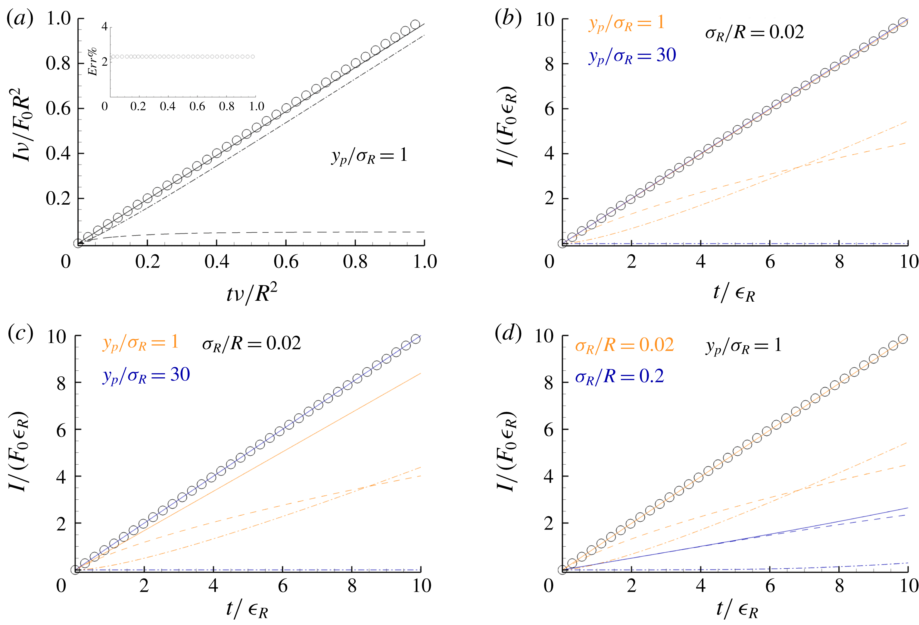
approaching zero. Figure 1(a) corresponds to a test case with the force applied close to the wall (
 $y_{p}/R=0.1$
) and
 $\unicode[STIX]{x1D708}\unicode[STIX]{x1D700}_{R}/R^{2}=4\times 10^{-3}$
, and shows that the impulse balance is satisfied within numerical accuracy on the (external) time scale
 $R^{2}/\unicode[STIX]{x1D708}$
. At steady state, the fluid impulse becomes constant and the drag impulse increases linearly with time, becoming dominant at large time. The correct evaluation of the friction drag impulse appears now in all its relevance for wall-bounded flows. Indeed, the approach we propose is able to generate vorticity at the wall in a physically consistent way as proved by the correct evaluation of the viscous shear stress at the wall. The relative error between the exact value of the total impulse
 $I_{E}$
and its numerical evaluation
 $I_{u}+I_{f}$
is shown in the inset of figure 1(a). The error does not accumulate in time.
A more subtle test concerns the impulse balance on the (inner) time scale of the regularisation parameter. Using
 $\unicode[STIX]{x1D700}_{R}$
as time in the dimensional analysis yields
 $$\begin{eqnarray}I_{u}^{\ast \ast }\left(\frac{t}{\unicode[STIX]{x1D700}_{R}},\frac{y_{p}}{\sqrt{2\unicode[STIX]{x1D708}\unicode[STIX]{x1D700}_{R}}},\frac{R}{\sqrt{2\unicode[STIX]{x1D708}\unicode[STIX]{x1D700}_{R}}}\right)+I_{f}^{\ast \ast }\left(\frac{t}{\unicode[STIX]{x1D700}_{R}},\frac{y_{p}}{\sqrt{2\unicode[STIX]{x1D708}\unicode[STIX]{x1D700}_{R}}},\frac{R}{\sqrt{2\unicode[STIX]{x1D708}\unicode[STIX]{x1D700}_{R}}}\right)=\frac{t}{\unicode[STIX]{x1D700}_{R}}\,,\end{eqnarray}$$
where, for example,
 $I_{u}/(F_{0}\unicode[STIX]{x1D700}_{R})=I_{u}^{\ast \ast }$
and, as in § 2,
 $\sqrt{2\unicode[STIX]{x1D708}\unicode[STIX]{x1D700}_{R}}=\unicode[STIX]{x1D70E}_{R}$
. This alternative dimensionless form stresses the behaviour of the solution on the time scale of the regularisation, corresponding to the diffusive length scale
 $\unicode[STIX]{x1D70E}_{R}$
, which is of the order of the mesh size to be adopted in the numerical solution. The purpose of checking the impulse balance in the above form is a more stringent check of the boundary conditions. In the theoretical description of the approach, the Green’s function of the domain was approximated using the method of images, mirroring the source with respect to the local tangent plane at the boundary.
Impulse balance (3.1) for a constant force
 $\boldsymbol{F}=(0,0,F_{0})$
applied at a fixed point
 $\boldsymbol{x}_{p}$
at distance
 $y_{p}=R-r_{p}$
from the wall. The fluid is initially at rest in the cylindrical domain
 ${\mathcal{D}}$
with periodic boundary condition at
 $z=0$
and
 $z=2\unicode[STIX]{x03C0}$
and no-slip boundary conditions at
 $r=R$
. Exact impulse
 $I_{E}=F_{0}\,t$
(open circles),
 $I_{u}(t)$
(dashed line),
 $I_{f}(t)$
(dash-dotted line) and
 $I_{u}+I_{f}$
(solid line). (a) Plot of the impulse normalised in external variables
 $\unicode[STIX]{x1D708}I/(F_{0}\,R^{2})$
versus dimensionless time
 $\unicode[STIX]{x1D708}t/R^{2}$
. The inset shows the normalised relative error
 $Err\%=100(I_{E}-I_{u}-I_{f})/I_{E}$
. (b–d) Plots of the impulse normalised in internal variables
 $I/(F_{0}\,\unicode[STIX]{x1D716}_{R})$
versus dimensionless time
 $t/\unicode[STIX]{x1D716}_{R}$
. (b,c) Colours label different wall-normal distances made dimensionless with the regularisation length scale
 $\unicode[STIX]{x1D70E}_{R}$
, namely
 $y_{p}/\unicode[STIX]{x1D70E}_{R}=1$
(orange lines) and
 $y_{p}/\unicode[STIX]{x1D70E}_{R}=30$
(blue lines) at
 $\unicode[STIX]{x1D70E}_{R}/R=0.02$
: (b) cases with image point force; (c) same cases as in (b) without the image point force. (d) The colours label the different regularisation length scale
 $\unicode[STIX]{x1D70E}_{R}$
made dimensionless with the pipe radius
 $R$
, namely
 $\unicode[STIX]{x1D70E}_{R}/R=0.02$
(orange lines) and
 $\unicode[STIX]{x1D70E}_{R}/R=0.2$
for a point force at fixed
 $y_{p}/\unicode[STIX]{x1D70E}_{R}=1$
.

Figure 1(b) shows the impulse balance for two wall-normal distances of the point force. In one case
 $y_{p}/\unicode[STIX]{x1D70E}_{R}=1$
(orange solid line) the distance of the source from the wall is comparable to the regularisation length scale
 $\unicode[STIX]{x1D70E}_{R}$
. In the other,
 $y_{p}/\unicode[STIX]{x1D70E}_{R}=30$
(blue solid line, almost totally superimposed on the orange one), the point force is relatively far from the wall. In both cases, the numerically evaluated impulse follows the exact solution (circles). In the first case (particle close to the wall), the fluid impulse
 $I_{u}$
(orange dashed line) is initially comparable with the drag impulse
 $I_{f}$
(orange dash-dotted line). On the contrary, in the second case, when the force is applied far from the boundary, the friction drag is negligible on the observed (inner) time scale and the total impulse is almost all provided by the fluid. Overall, the result shows that the boundary condition and the associated vorticity generation are correctly captured by the algorithm. Figure 1(c) illustrates the role of mirror image of the force by plotting results obtained by removing the image contribution. One expects that the effect of the image should be negligible when
 $y_{p}/\unicode[STIX]{x1D70E}_{R}\gg 1$
. This is indeed the case, as shown by the comparison of the blue lines with the corresponding ones in figure 1(b). On the contrary, when the distance of the application point is comparable with the regularisation length,
 $y_{p}/\unicode[STIX]{x1D70E}_{R}\leqslant 1$
, the contribution of the image is crucial, as seen when comparing the orange solid lines with the corresponding ones in figure 1(b). Since, for computational efficiency, the adopted Green’s function is only approximate, it is important to identify the range of validity of the approximation. The curvature of the wall, measured in terms of the regularisation length scale, is a crucial parameter that determines the accuracy. Figure 1(d) shows that, when
 $\unicode[STIX]{x1D70E}_{R}/R$
is sufficiently small (orange curves), the error is negligible. The error becomes larger as soon as this ratio increases (blue curves, wall curvature comparable with the regularisation length).
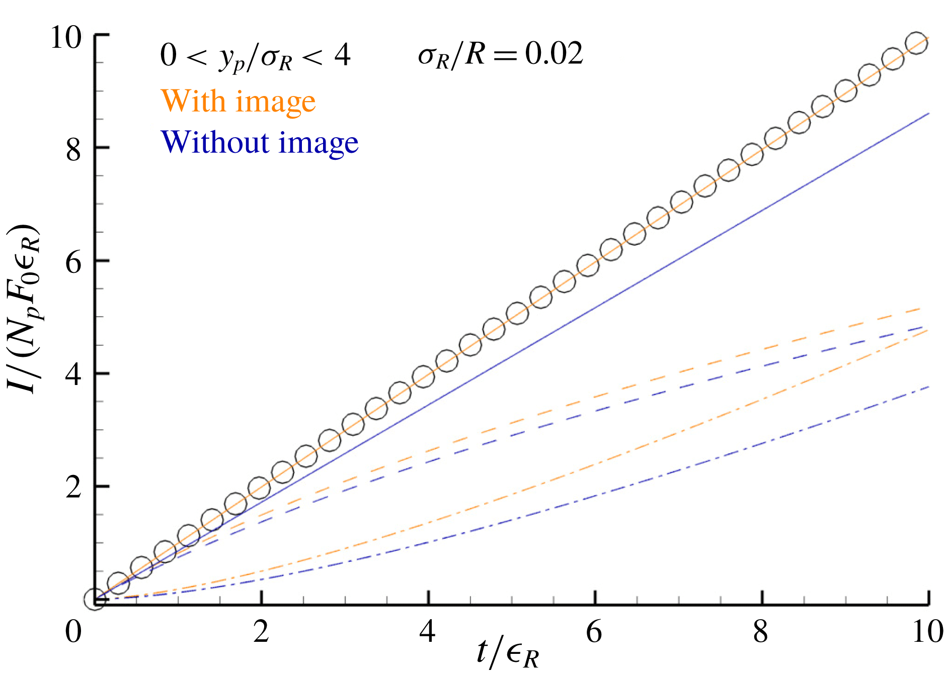
Figure 2 stresses the results of figure 1, with emphasis on turbulent wall-bounded flows. As discussed in more detail in the following sections, inertial particles tend to accumulate in the viscous sublayer near the wall. The data reported in the figure artificially reproduce these conditions, by considering
 $N_{p}=100\,000$
randomly distributed point forces placed in an annular shell close to the cylindrical wall. As apparent in the plots, using the mirror images (orange curves) provides the total impulse. On the contrary, neglecting the images (blue symbols) completely spoils the quality of the simulation.
Impulse balance (3.1) for a constant force
 $\boldsymbol{F}=(0,0,F_{0})$
applied to
 $N_{p}$
fixed points
 $\boldsymbol{x}_{p}$
in the cylindrical domain
 ${\mathcal{D}}$
to the fluid initially at rest. The normalised impulse
 $I/(N_{p}F_{0}\unicode[STIX]{x1D716}_{R})$
is plotted versus time
 $t$
made dimensionless with the regularisation time scale
 $\unicode[STIX]{x1D716}_{R}$
. Exact impulse
 $I_{E}$
(open circles),
 $I_{u}(t)$
(dashed line),
 $I_{f}(t)$
(dash-dotted line) and
 $I_{u}+I_{f}$
(solid line). Here
 $N_{p}=100\,000$
point forces are applied at points
 $\boldsymbol{x}_{p}$
randomly distributed in the stripe
 $0<y_{p}/\unicode[STIX]{x1D70E}_{R}<4$
near the wall for
 $\unicode[STIX]{x1D70E}_{R}/R=0.02$
. The colours label cases with image point forces (orange lines) and without the images (blue line).

4 Particle-laden turbulent pipe flow
4.1 Simulation set-up
The ERPP formulation is applied to a fully developed turbulent pipe flow. The dimensionless forms of equations (2.12) are solved in a cylindrical domain
 ${\mathcal{D}}=[0:R]\times [0:2\unicode[STIX]{x03C0}]\times [0:L_{z}]$
where the (dimensionless) pipe radius is
 $R=1$
. Periodic boundary conditions are applied in the axial (
 $z$
) direction, with
 $L_{z}=2\unicode[STIX]{x03C0}$
. The subscript
 $R$
which is used to denote the regularised field will be dropped hereafter to ease notation. The reference quantities are the fluid density
 $\unicode[STIX]{x1D70C}_{f}$
, the pipe radius
 $R$
, the bulk velocity of the purely Newtonian case
 $U_{b}=Q_{0}/(\unicode[STIX]{x03C0}R^{2})$
, where
 $Q_{0}$
is the flow rate of the reference uncoupled case, and the viscosity
 $\unicode[STIX]{x1D707}$
.
The flow is sustained by a constant mean pressure gradient applied in the direction of the axial unit vector
 $\boldsymbol{e}_{z}$
, with the dimensionless pressure expressed as
 $P=\text{d}p/\text{d}z|_{0}(z-z_{0})+p(r,\unicode[STIX]{x1D703},z,t)$
:
 $$\begin{eqnarray}\left.\begin{array}{@{}c@{}}\displaystyle \unicode[STIX]{x1D735}\boldsymbol{\cdot }\boldsymbol{u}=0,\\ \displaystyle \frac{\unicode[STIX]{x2202}\boldsymbol{u}}{\unicode[STIX]{x2202}t}+\unicode[STIX]{x1D735}\boldsymbol{\cdot }(\boldsymbol{u}\otimes \boldsymbol{u})=-\unicode[STIX]{x1D735}p+\frac{1}{Re_{b}}\unicode[STIX]{x1D6FB}^{2}\boldsymbol{u}+\boldsymbol{f}-\left.\frac{\text{d}p}{\text{d}z}\right|_{0}\boldsymbol{e}_{z}.\end{array}\right\}\end{eqnarray}$$
The Reynolds number is
 $Re_{b}=U_{b}R/\unicode[STIX]{x1D708}$
and the field
 $\boldsymbol{f}$
is the particle feedback on the fluid:
 $$\begin{eqnarray}\boldsymbol{f}=-\mathop{\sum }_{p}^{N_{p}}\boldsymbol{D}_{p}(t-\unicode[STIX]{x1D716})\,g[\boldsymbol{x}-\boldsymbol{x}_{p}(t-\unicode[STIX]{x1D716}),\unicode[STIX]{x1D716}]+\tilde{\boldsymbol{D}}_{p}(t-\unicode[STIX]{x1D716})\,g[\boldsymbol{x}-\tilde{\boldsymbol{x}}_{p}(t-\unicode[STIX]{x1D716}),\unicode[STIX]{x1D716}].\end{eqnarray}$$
The system consists of the carrier Newtonian fluid and
 $N_{p}$
particles. The dimensionless drag force on the
 $p$
th particle is
 $\boldsymbol{D}_{p}=3\unicode[STIX]{x03C0}d_{p}/Re_{b}(\boldsymbol{u}|_{p}+d_{p}^{2}/24\unicode[STIX]{x1D6FB}^{2}\boldsymbol{u}|_{p}-\boldsymbol{v}_{p})$
, where
 $d_{p}$
is the dimensionless particle diameter,
 $\boldsymbol{v}_{p}$
is the particle velocity and
 $\boldsymbol{u}|_{p}=\boldsymbol{u}(\boldsymbol{x}_{p},t)$
is the fluid velocity at the particle position. Both the current time
 $t$
and the regularisation time scale
 $\unicode[STIX]{x1D716}_{R}$
are made dimensionless with
 $R/U_{b}$
, that is,
 $\unicode[STIX]{x1D716}=\unicode[STIX]{x1D716}_{R}U_{b}/R$
.
Impermeability and no-slip conditions are enforced at the pipe wall. Equations (4.1) are solved in cylindrical coordinates by exploiting a second-order finite difference on a staggered grid (see Battista, Picano & Casciola Reference Battista, Picano and Casciola2014; Costantini, Mollicone & Battista Reference Costantini, Mollicone and Battista2018). The classical Chorin projection method (Chorin Reference Chorin1968; Rannacher Reference Rannacher1992) is used to enforce the divergence-free constraint imposed by the mass balance. Both convective and diffusive terms are explicitly integrated in time using a third-order low-storage Runge–Kutta method.
As is customary, inner or wall units are given in terms of the viscous length
 $\ell _{\ast }=\unicode[STIX]{x1D708}/u_{\ast }$
and the friction velocity
 $u_{\ast }=\sqrt{\unicode[STIX]{x1D70F}_{w}/\unicode[STIX]{x1D70C}_{f}}$
, with
 $\unicode[STIX]{x1D70F}_{w}$
the average wall shear stress. The distance from the pipe wall in inner units is denoted
 $y_{+}=(1-r)Re_{\ast }$
, where the friction Reynolds number is
 $Re_{\ast }=u_{\ast }R/\unicode[STIX]{x1D708}$
. The same distance in external units is denoted by
 $y=1-r$
.
All the simulations are performed with the same friction Reynolds number
 $Re_{\ast }=180$
. The corresponding bulk Reynolds number for a purely Newtonian (no particle back-reaction) flow is
 $Re_{b}=2650$
. The grid resolution is
 $N_{\unicode[STIX]{x1D703}}\times N_{r}\times N_{z}=576\times 129\times 576$
in the azimuthal, wall-normal and axial directions, respectively. The grid in the radial direction is clustered near the wall with a minimum spacing of
 $\unicode[STIX]{x0394}r_{+}|_{w}=0.5$
which gradually increases towards the centreline reaching
 $\unicode[STIX]{x0394}r_{+}|_{0}=2$
. The grid resolution in the azimuthal and axial directions is
 $(R\unicode[STIX]{x0394}\unicode[STIX]{x1D703})_{+}=3.2$
and
 $\unicode[STIX]{x0394}z_{+}=3.2$
, respectively.
Given the large particle-to-fluid density ratio
 $\unicode[STIX]{x1D70C}_{p}/\unicode[STIX]{x1D70C}_{f}$
, the only relevant hydrodynamic force is the Stokes drag where the Faxen correction is accounted for (see Gatignol Reference Gatignol1983; Maxey & Riley Reference Maxey and Riley1983). Newton’s equations for the particles reduce to
 $$\begin{eqnarray}\left.\begin{array}{@{}c@{}}\displaystyle \frac{\text{d}\boldsymbol{x}_{p}}{\text{d}t}=\boldsymbol{v}_{p},\\ \displaystyle \frac{\text{d}\boldsymbol{v}_{p}}{\text{d}t}=\frac{1}{St_{b}}\left(\boldsymbol{u}|_{p}+\frac{d_{p}^{2}}{24}\unicode[STIX]{x1D6FB}^{2}\boldsymbol{u}|_{p}-\boldsymbol{v}_{p}\right),\end{array}\right\}\end{eqnarray}$$
where the bulk Stokes number is
 $St_{b}=\unicode[STIX]{x1D70F}_{p}U_{b}/R=\unicode[STIX]{x1D70C}_{p}/(18\unicode[STIX]{x1D70C}_{f})\text{Re}_{b}d_{p}^{2}$
, with
 $\unicode[STIX]{x1D70F}_{p}$
the Stokes relaxation time of the particle.
In (4.3) and in the expression for the drag force (4.2),
 $\boldsymbol{u}|_{p}$
and
 $\unicode[STIX]{x1D6FB}^{2}\boldsymbol{u}|_{p}$
are the fluid velocity and its Laplacian evaluated at the particle position taking into account the background fluid velocity including the disturbance of all the particles except the
 $p$
th one. This field is evaluated by summing the contributions of all the particles and by successively removing the particle self-disturbance. This step is easily performed with the ERPP approach where the self-disturbance velocity can be computed in a closed analytical form.
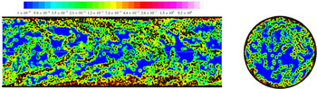
Snapshot of the particle back-reaction field intensity (colour) and particle configuration (black dots) for an instantaneous field at
 $\unicode[STIX]{x1D719}=0.4$
,
 $St_{+}=10$
and
 $\unicode[STIX]{x1D70C}_{p}/\unicode[STIX]{x1D70C}_{f}=180$
. The flow is from left to right.

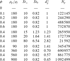
Simulation matrix. All runs are performed by imposing the same mean pressure gradient corresponding to a friction Reynolds number of
 $Re_{\ast }=180$
. The bulk Reynolds number for the reference case where the particles do not back-react on the fluid (one-way coupling) is
 $Re_{b}=2650$
. The grid resolution is
 $N_{\unicode[STIX]{x1D703}}\times N_{r}\times N_{z}=576\times 129\times 576$
corresponding to
 $\unicode[STIX]{x0394}r^{+}|_{w}=0.5$
at the wall and
 $\unicode[STIX]{x0394}r^{+}|_{0}=2$
at the centreline. The resolution in the azimuthal and axial directions is
 $(R\unicode[STIX]{x0394}\unicode[STIX]{x1D703})_{+}=3.2$
and
 $\unicode[STIX]{x0394}z_{+}=3.2$
, respectively. The mass loading is defined as
 $\unicode[STIX]{x1D719}=\unicode[STIX]{x1D70C}_{p}N_{p}V_{p}/\unicode[STIX]{x1D70C}_{f}V_{f}$
, where
 $N_{p}$
is the number of particles,
 $V_{f}$
is the volume of the fluid in the domain
 ${\mathcal{D}}=[0:R]\times [0:2\unicode[STIX]{x03C0}]\times [0:L_{z}]$
and
 $\unicode[STIX]{x1D70C}_{p}/\unicode[STIX]{x1D70C}_{f}$
denotes the particle-to-fluid density ratio. Parameter
 $St_{+}$
is the Stokes number in internal units and
 $St_{0}$
is the Stokes number in external units, namely
 $St_{0}=\unicode[STIX]{x1D70F}_{p}/\unicode[STIX]{x1D70F}_{0}$
with
 $\unicode[STIX]{x1D70F}_{0}=R/U_{b}$
,
 $U_{b}$
being the bulk velocity in the uncoupled case. The column labelled
 $d_{p}^{+}$
shows the particle diameter in wall units, and
 $N_{p}$
denotes the number of particles in the domain
 ${\mathcal{D}}$
.

It is instrumental to introduce the inner Stokes number,
 $St_{+}=\unicode[STIX]{x1D70F}_{p}\ell _{\ast }/u_{\ast }=St_{0}Re_{\ast }^{2}/Re_{b}$
. In two-way coupled simulations, a further dimensionless parameter that quantifies the particle back-reaction on the fluid is the mass loading of the suspension. This is defined as the ratio between the total mass of the dispersed phase and the fluid mass:
 $\unicode[STIX]{x1D719}=N_{p}\unicode[STIX]{x1D70C}_{p}V_{p}/\unicode[STIX]{x1D70C}_{f}V_{f}=(\unicode[STIX]{x1D70C}_{p}/\unicode[STIX]{x1D70C}_{f})N_{p}d_{p}^{2}/(12\unicode[STIX]{x03C0})$
, where
 $V_{p}$
is the volume of the particle and
 $V_{f}=\unicode[STIX]{x03C0}R^{3}L_{z}$
(
 $L_{z}=2\unicode[STIX]{x03C0}$
is the dimensionless axial extension of the domain) is the volume of the fluid in the domain
 ${\mathcal{D}}$
. In the expression for the mass loading,
 $\unicode[STIX]{x1D719}_{V}=N_{p}V_{p}/V_{f}=N_{p}d_{p}^{2}/(12\unicode[STIX]{x03C0})$
is the volume fraction.
In conclusion, the dynamics is controlled by a set of four dimensionless parameters,
 $\{Re_{\ast };\,St_{+};\unicode[STIX]{x1D719};\unicode[STIX]{x1D70C}_{p}/\unicode[STIX]{x1D70C}_{f}\}$
. The physical assumptions behind this description of the particle-laden flow are: (i) the density ratio
 $\unicode[STIX]{x1D70C}_{p}/\unicode[STIX]{x1D70C}_{f}$
is sufficiently large such that only the Stokes drag matters in the particle dynamics and (ii) the particle diameter
 $d_{p}^{+}=d_{p}Re_{\ast }$
is small, which means that the particles are at most of the same order of magnitude as the viscous length.
The parameters for the different cases are summarised in table 1. The friction Reynolds number is fixed (i.e. the pressure drop is constant). The simulations are divided into three groups. In the first set, the mass loading
 $\unicode[STIX]{x1D719}$
is changed keeping Stokes number and density ratio fixed. The second set addresses the effects of the Stokes number at fixed mass loading and density ratio. Finally, the density ratio is changed at fixed mass loading and Stokes number to explore the effect of the number of particles.
A snapshot of the particle back-reaction intensity on the fluid and the instantaneous particle configuration is provided in figure 3 for the reference case at
 $\unicode[STIX]{x1D719}=0.4$
,
 $St_{+}=10$
and
 $\unicode[STIX]{x1D70C}_{p}/\unicode[STIX]{x1D70C}_{f}=180$
. Note the particle accumulation in the near-wall region and the strict correlation between the particle configuration and the Eulerian structure of the back-reaction. Coherent particle structures extend from the wall up to the centre of the pipe resembling the hairpin-like structures typical of wall-bounded flows.
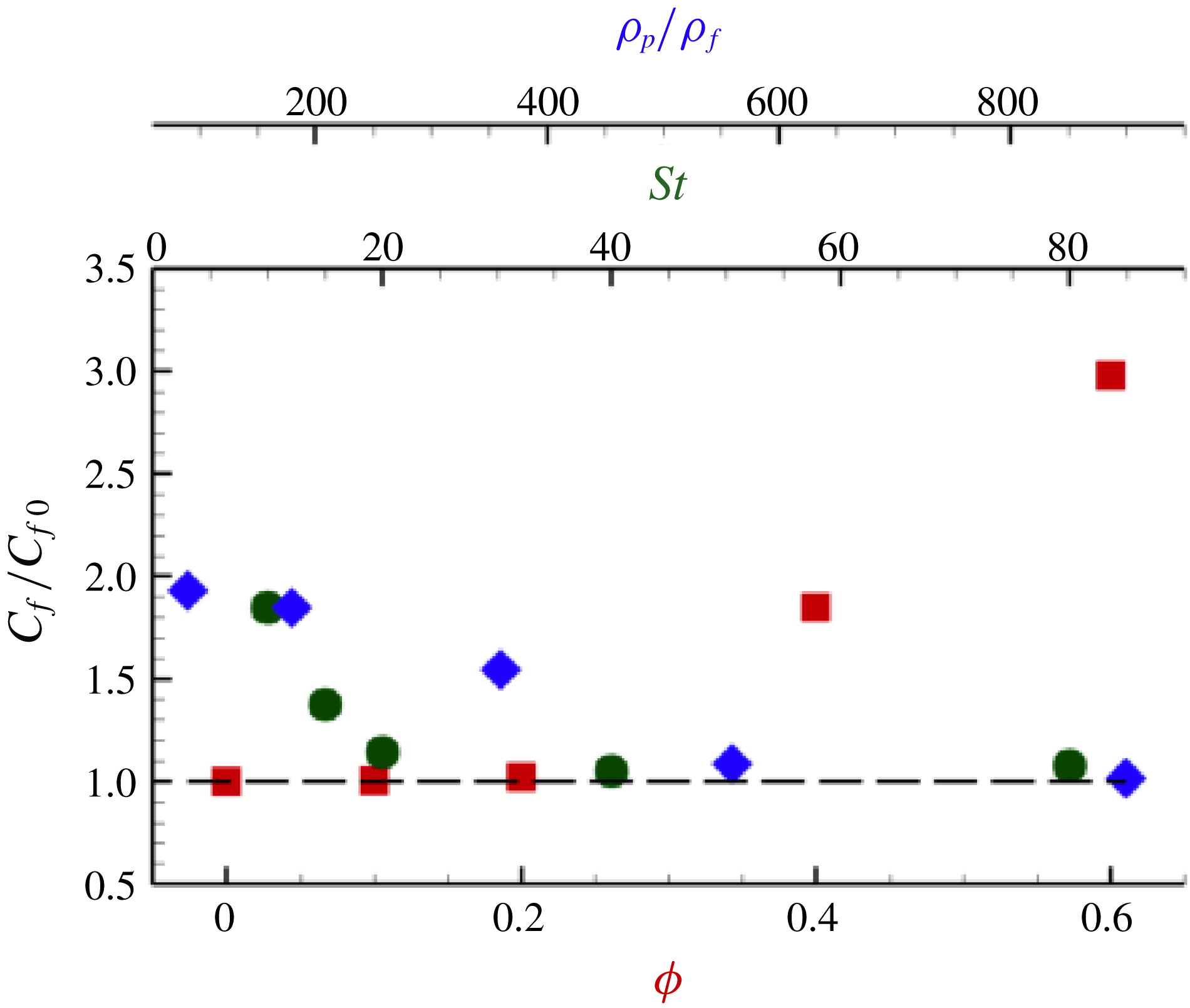
Friction coefficient of the two-way coupled simulations
 $C_{f}$
normalised with corresponding friction coefficient of the uncoupled case
 $C_{f0}$
; see (4.4). The dataset is plotted as a function of the mass loading
 $\unicode[STIX]{x1D719}$
(red squares) at fixed
 $St_{+}=10$
and
 $\unicode[STIX]{x1D70C}_{p}/\unicode[STIX]{x1D70C}_{f}=180$
, as a function of the Stokes number
 $St_{+}$
(green circles) at fixed
 $\unicode[STIX]{x1D719}=0.4$
and
 $\unicode[STIX]{x1D70C}_{p}/\unicode[STIX]{x1D70C}_{f}=180$
and as a function of the particle-to-fluid density ratio
 $\unicode[STIX]{x1D70C}_{p}/\unicode[STIX]{x1D70C}_{f}$
(blue diamonds) at fixed
 $\unicode[STIX]{x1D719}=0.4$
and
 $St_{+}=10$
.

4.2 Skin friction coefficient
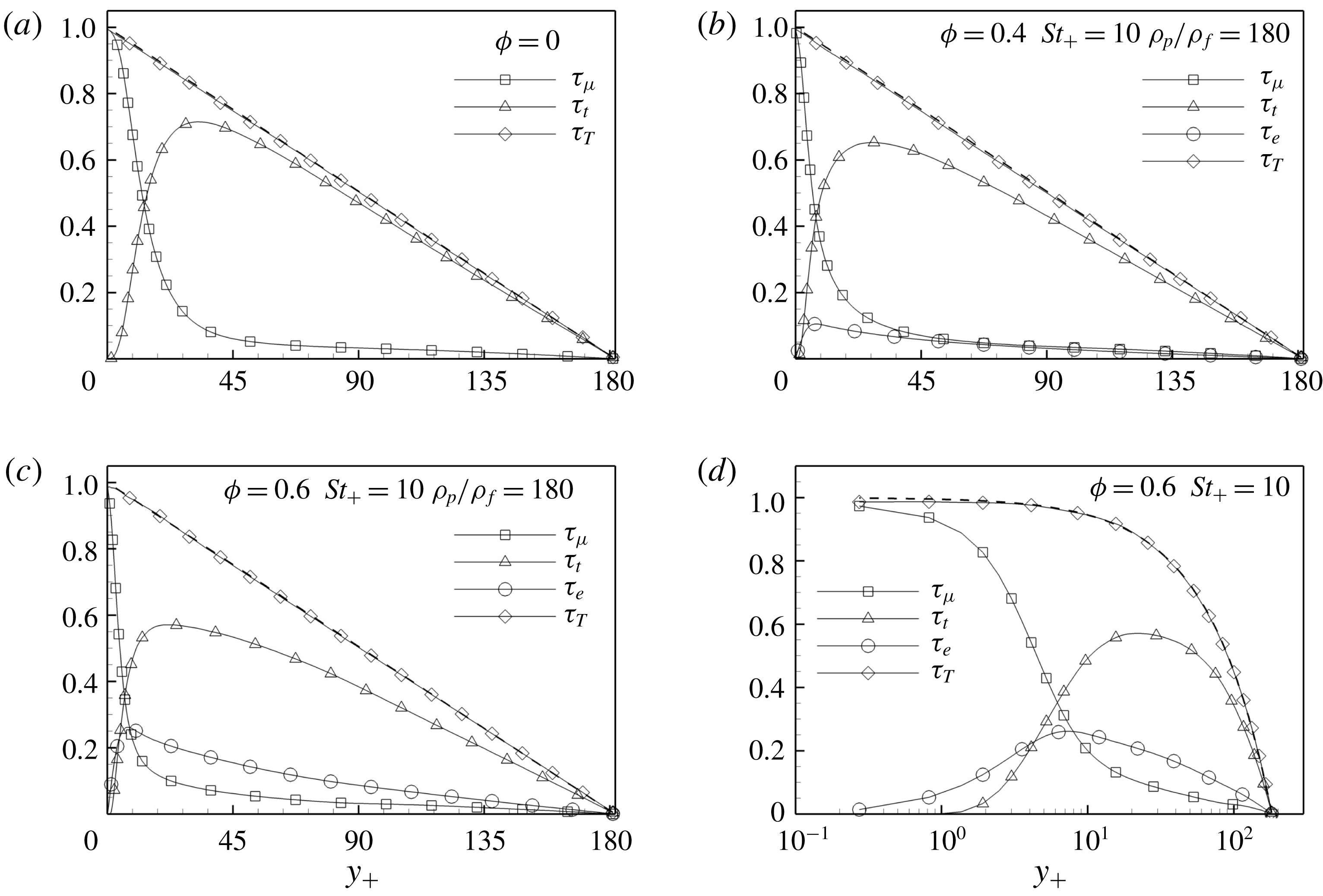
Normalised mean stress balance (4.5) against wall-normal distance
 $y_{+}=(R-r)/y_{\ast }$
. Viscous stress
 $\unicode[STIX]{x1D70F}_{\unicode[STIX]{x1D707}}$
(▫), turbulent stress
 $\unicode[STIX]{x1D70F}_{t}$
(▵), extra stress
 $\unicode[STIX]{x1D70F}_{e}$
(○), total stress
 $\unicode[STIX]{x1D70F}_{T}=\unicode[STIX]{x1D70F}_{\unicode[STIX]{x1D707}}+\unicode[STIX]{x1D70F}_{t}+\unicode[STIX]{x1D70F}_{e}$
(♢) and
 $\text{d}p/\text{d}z|_{0}\,r$
(dashed line) (see text for definitions). All stresses are normalised with the wall shear stress
 $\unicode[STIX]{x1D70F}_{w}$
. (a) Uncoupled case; (b) case
 $\unicode[STIX]{x1D719}=0.4$
and
 $St_{+}=10$
; (c) case
 $\unicode[STIX]{x1D719}=0.6$
and
 $St_{+}=10$
; (d) same as (c) but in semi-logarithmic scale.

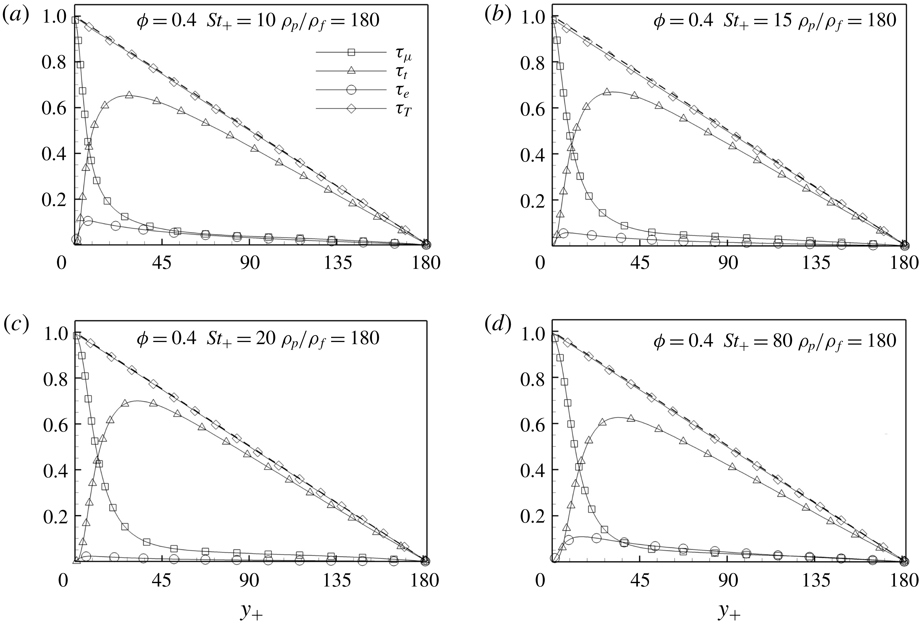
Normalised mean stress balance (4.5) against the wall-normal distance
 $y_{+}=(R-r)/y_{\ast }$
. Viscous stress
 $\unicode[STIX]{x1D70F}_{\unicode[STIX]{x1D707}}$
(▫), turbulent stress
 $\unicode[STIX]{x1D70F}_{t}$
(▵), extra stress
 $\unicode[STIX]{x1D70F}_{e}$
(○), total stress
 $\unicode[STIX]{x1D70F}_{T}=\unicode[STIX]{x1D70F}_{\unicode[STIX]{x1D707}}+\unicode[STIX]{x1D70F}_{t}+\unicode[STIX]{x1D70F}_{e}$
(♢) and
 $\text{d}p/\text{d}z|_{0}\,r$
(dashed line) (see text for definitions). All stresses are normalised with the wall shear stress
 $\unicode[STIX]{x1D70F}_{w}$
. (a) Case
 $\unicode[STIX]{x1D719}=0.4$
,
 $St_{+}=10$
; (b)
 $\unicode[STIX]{x1D719}=0.4$
,
 $St_{+}=15$
; (c)
 $\unicode[STIX]{x1D719}=0.4$
,
 $St_{+}=20$
; (d)
 $\unicode[STIX]{x1D719}=0.4$
,
 $St_{+}=80$
.

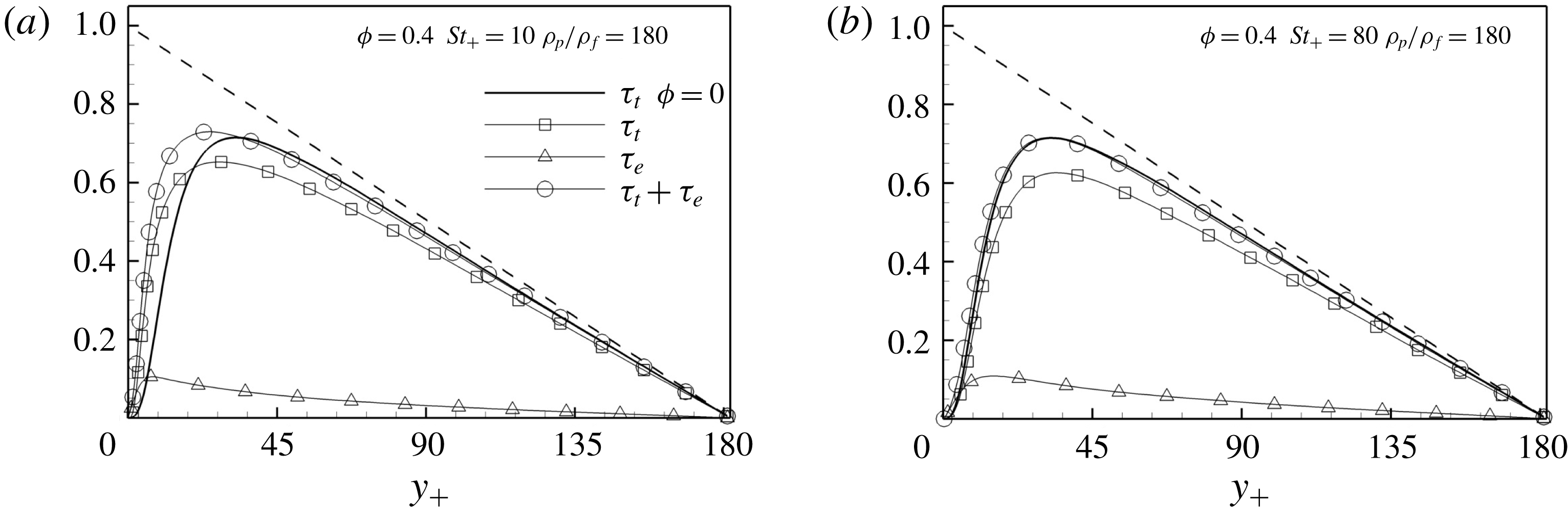
Normalised mean stress balance (4.5) against the wall-normal distance
 $y_{+}=(R-r)/y_{\ast }$
. Turbulent stress
 $\unicode[STIX]{x1D70F}_{t}$
(▫), turbulent stress
 $\unicode[STIX]{x1D70F}_{t}$
in the uncoupled case (solid line), extra stress
 $\unicode[STIX]{x1D70F}_{e}$
(▵),
 $\unicode[STIX]{x1D70F}_{t}+\unicode[STIX]{x1D70F}_{e}$
(○) and
 $\text{d}p/\text{d}z|_{0}\,r$
(dashed line) (see text for definitions). All stresses are normalised with the wall shear stress
 $\unicode[STIX]{x1D70F}_{w}$
. (a) Case
 $\unicode[STIX]{x1D719}=0.4$
,
 $St_{+}=10$
,
 $\unicode[STIX]{x1D70C}_{p}/\unicode[STIX]{x1D70C}_{f}=180$
; (b)
 $\unicode[STIX]{x1D719}=0.4$
,
 $St_{+}=80$
,
 $\unicode[STIX]{x1D70C}_{p}/\unicode[STIX]{x1D70C}_{f}=180$
.

The particles in fully developed turbulent pipe flow modify the drag with respect to the uncoupled (Newtonian) case. This alteration non-trivially depends on mass loading, Stokes number and particle-to-fluid density ratio. Figure 4 shows the friction coefficient
 $$\begin{eqnarray}C_{f}=\frac{2\,\unicode[STIX]{x1D70F}_{w}}{\unicode[STIX]{x1D70C}_{f}U^{2}}=\frac{\left.\text{d}p/\text{d}z\right|_{0}}{\unicode[STIX]{x1D70C}_{f}U^{2}},\end{eqnarray}$$
where
 $U=Q/(\unicode[STIX]{x03C0}R^{2})$
is the bulk velocity,
 $Q$
is the flow rate and
 $\text{d}p/\text{d}z|_{0}$
is the pressure gradient. In the figure,
 $C_{f}$
is normalised with the unladen value,
 $C_{f0}$
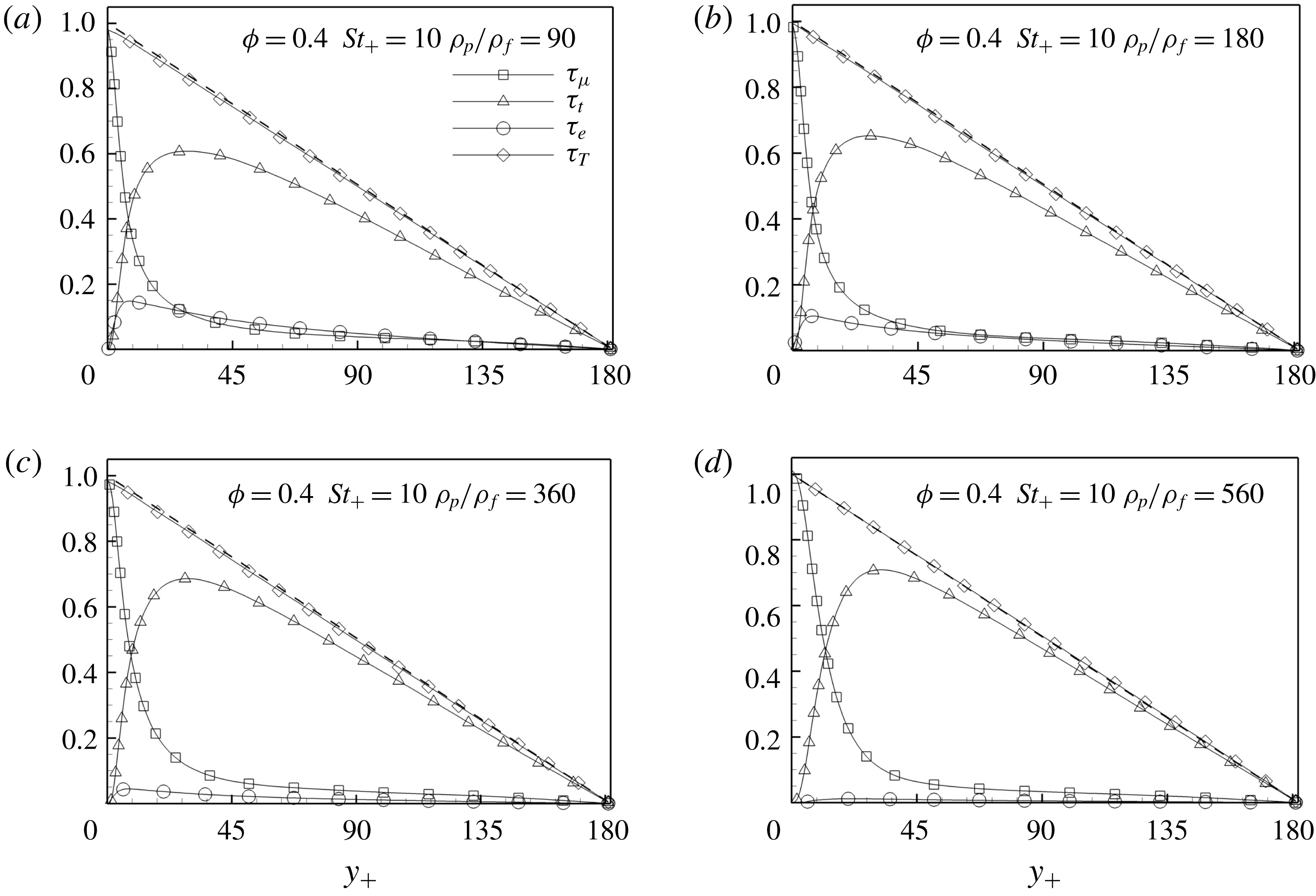
, and plotted as a function of mass loading (squares), Stokes number (circles) and particle-to-fluid density ratio (diamonds). Since the pressure drop is kept constant, an increase in friction coefficient corresponds to a decrease in mass flow rate. The figure shows that the drag increases at increasing mass loading and decreases with Stokes number and density ratio. In the present range of parameters, the friction coefficient is always greater than or at most equal to the uncoupled case value.
Normalised mean stress balance (4.5) against the wall-normal distance
 $y_{+}=(R-r)/y_{\ast }$
. Viscous stress
 $\unicode[STIX]{x1D70F}_{\unicode[STIX]{x1D707}}$
(▫), turbulent stress
 $\unicode[STIX]{x1D70F}_{t}$
(▵), extra stress
 $\unicode[STIX]{x1D70F}_{e}$
(○), total stress
 $\unicode[STIX]{x1D70F}_{T}=\unicode[STIX]{x1D70F}_{\unicode[STIX]{x1D707}}+\unicode[STIX]{x1D70F}_{t}+\unicode[STIX]{x1D70F}_{e}$
(♢) and
 $\text{d}p/\text{d}z|_{0}\,r$
(dashed line) (see text for definitions). All stresses are normalised with the wall shear stress
 $\unicode[STIX]{x1D70F}_{w}$
. In all panels
 $\unicode[STIX]{x1D719}=0.4$
,
 $St_{+}=10$
, and (a)
 $\unicode[STIX]{x1D70C}_{p}/\unicode[STIX]{x1D70C}_{f}=90$
; (b)
 $\unicode[STIX]{x1D70C}_{p}/\unicode[STIX]{x1D70C}_{f}=180$
; (c)
 $\unicode[STIX]{x1D70C}_{p}/\unicode[STIX]{x1D70C}_{f}=360$
; (d)
 $\unicode[STIX]{x1D70C}_{p}/\unicode[STIX]{x1D70C}_{f}=560$
.

4.3 Mean momentum balance
The drag modification is attributed to the alteration of the different contributions to the stress balance (see e.g. Fukagata, Iwamoto & Kasagi Reference Fukagata, Iwamoto and Kasagi2002):
 $$\begin{eqnarray}\unicode[STIX]{x1D707}\frac{\unicode[STIX]{x2202}U_{z}}{\unicode[STIX]{x2202}r}-\unicode[STIX]{x1D70C}_{f}\langle u_{r}^{\prime }\,u_{z}^{\prime }\rangle +\frac{1}{r}\int _{0}^{r}\unicode[STIX]{x1D702}F_{z}\,\text{d}\unicode[STIX]{x1D702}=\frac{1}{2}\left.\frac{\text{d}p}{\text{d}z}\right|_{0}\,r,\end{eqnarray}$$
where
 $U_{z}=\langle u_{z}\rangle$
is the mean axial velocity,
 $-\unicode[STIX]{x1D70C}_{f}\langle u_{r}^{\prime }\,u_{z}^{\prime }\rangle$
is the turbulent Reynolds shear stress and
 $F_{z}=\langle f_{z}\rangle$
is the mean axial back-reaction, with angular brackets denoting ensemble average and primed variables representing fluctuations. In the absence of particles, the total shear stress, which is the sum of viscous stress,
 $\unicode[STIX]{x1D70F}_{\unicode[STIX]{x1D707}}=\unicode[STIX]{x1D707}\unicode[STIX]{x2202}U_{z}/\unicode[STIX]{x2202}r$
, and of turbulent Reynolds shear stress,
 $\unicode[STIX]{x1D70F}_{t}=-\unicode[STIX]{x1D70C}_{f}\langle u_{r}^{\prime }\,u_{z}^{\prime }\rangle$
, is a linear function of the radial coordinate. This result can be derived by integrating once the mean axial momentum balance (see the classical textbook by Pope (Reference Pope2001)). Following the same procedure, in the presence of a dispersed phase, the particle-induced extra stress,
 $\unicode[STIX]{x1D70F}_{e}=(1/r)\int _{0}^{r}\unicode[STIX]{x1D702}F_{z}\,\text{d}\unicode[STIX]{x1D702}$
, arises but the sum of the three stresses is still a linear function of the radial coordinate as imposed by the global axial momentum balance. This should not be taken for granted in a direct numerical simulation, unless some care is devoted to reach the statistically steady state and acquire well-converged statistics. The critical cases correspond to large mass loading (large number of particles) and large Stokes number and/or small density ratio (small number of particles). The former is due to the large computational cost, the latter due to the long runs required to have converged statistics.
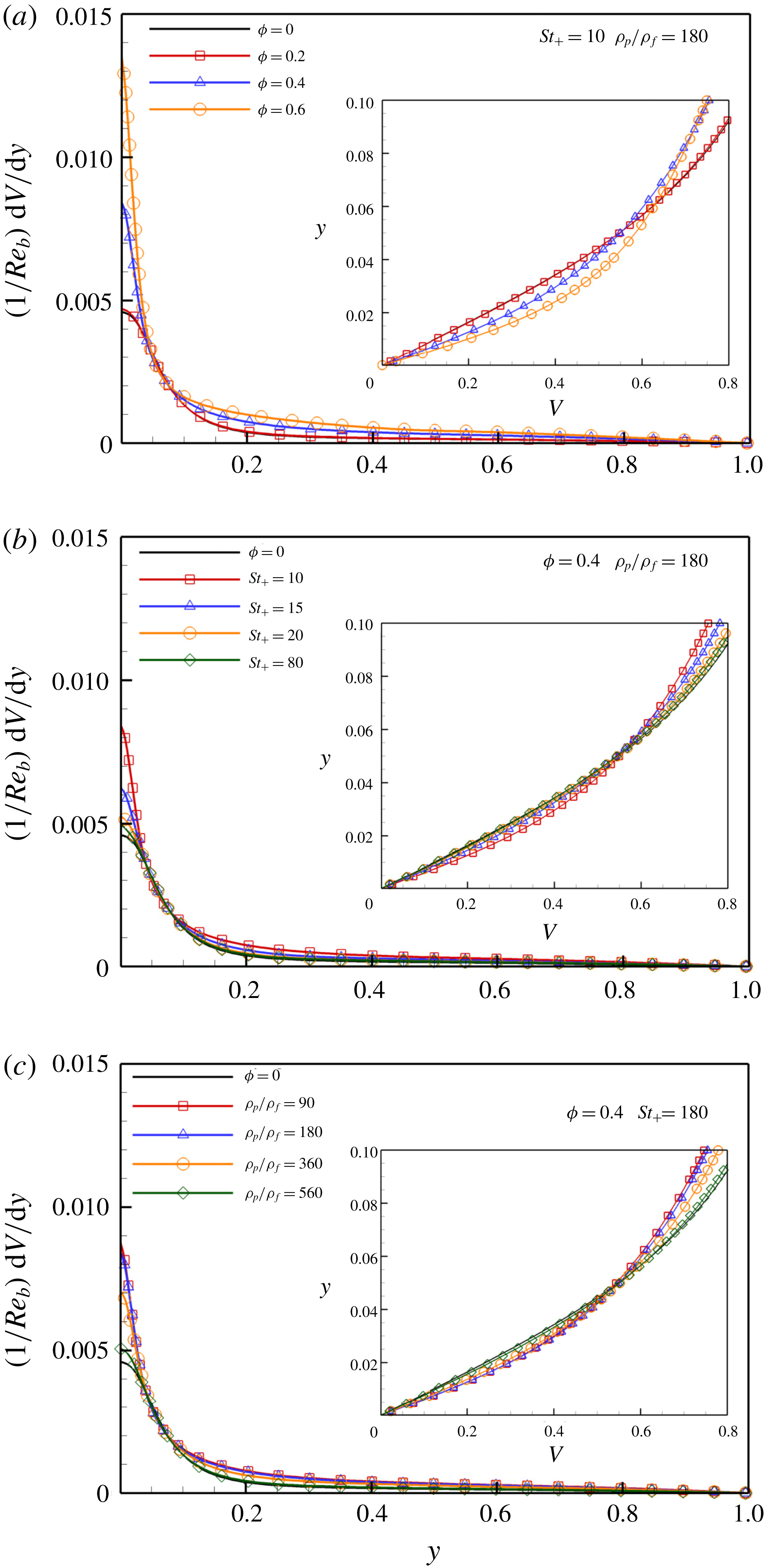
Normalised mean viscous stress profiles against the wall-normal distance
 $y=(R-r)/R$
. The insets report the mean velocity profile normalised with the bulk velocity,
 $V=U_{z}/U_{b}$
, against the wall-normal distance close to the wall.

Figure 5 shows the balance of (4.5) for
 $\unicode[STIX]{x1D719}=0$
(uncoupled),
 $\unicode[STIX]{x1D719}=0.4$
and
 $\unicode[STIX]{x1D719}=0.6$
. The turbulent stress is attenuated almost everywhere and its peak shifts towards the wall. Indeed, an extra stress arises that can be interpreted as an additional momentum flux towards the wall that modifies the turbulence dynamics and is at the origin of the drag increase. Its effect intensifies with increasing mass loading.
Figure 6 shows how the extra stress and the Reynolds shear stress profiles shift away from the wall at increasing Stokes number. As a consequence, the drag at
 $St_{+}=10$
is significantly higher than the drag at
 $St_{+}=80$
even though the extra stress has comparable values. Figure 7 goes deeper into the comparison with the uncoupled case, by considering
 $\unicode[STIX]{x1D70F}_{t}+\unicode[STIX]{x1D70F}_{e}$
at
 $St_{+}=10$
and
 $St_{+}=80$
and the turbulent Reynolds shear stress. At
 $St_{+}=10$
, the profile of
 $\unicode[STIX]{x1D70F}_{t}+\unicode[STIX]{x1D70F}_{e}$
peaks much closer to the wall and is more intense than the uncoupled turbulent Reynolds stress profile. On the other hand, the distribution of
 $\unicode[STIX]{x1D70F}_{t}+\unicode[STIX]{x1D70F}_{e}$
closely reproduces the uncoupled Reynolds stress at
 $St_{+}=80$
. This combination further explains the difference in the drag between
 $St_{+}=10$
and
 $St_{+}=80$
.
To complete the discussion about the friction coefficients, the effect of the particle-to-fluid density ratio on the stress contributions is shown in figure 8. The drag modification occurs since (i) the extra stress decreases with increasing density ratio, becoming negligible at
 $\unicode[STIX]{x1D70C}_{p}/\unicode[STIX]{x1D70C}_{f}=560$
(the behaviour is similar at
 $\unicode[STIX]{x1D70C}_{p}/\unicode[STIX]{x1D70C}_{f}=900$
and is not shown) and (ii) the turbulent Reynolds stress peak increases and departs from the wall region.
The particle feedback produces two concurrent effects: the depletion of the turbulent Reynolds shear stress and the presence of the particle extra stress. The latter produces an increase of momentum flux towards the wall. The extra stress is then mainly balanced by the viscous stress since the turbulent Reynolds shear stress approaches zero. The modification of the viscous stress results in a modification of the drag as shown in figure 4. To better highlight this behaviour, figure 9 reports the normalised mean viscous stress profiles as a function of the wall distance, with insets showing a close-up view of the normalised mean axial velocity profile. When the particle extra stress provides a significant momentum flux towards the wall, the fluid velocity increases with respect to the uncoupled case. As a consequence, the viscous stress increases and the friction follows the same fate. The main modification of the stress balance clearly occurs close to the wall. The extended ERPP method has been designed to capture the particle–fluid interaction close to a solid boundary accounting for the correct rate of vorticity generation which, in turn, results in a physically consistent representation of the viscous shear stress and thus of the overall drag. This is a distinct characteristic of the present approach which allows the prediction of the increase in drag.
4.4 Mean particle concentration
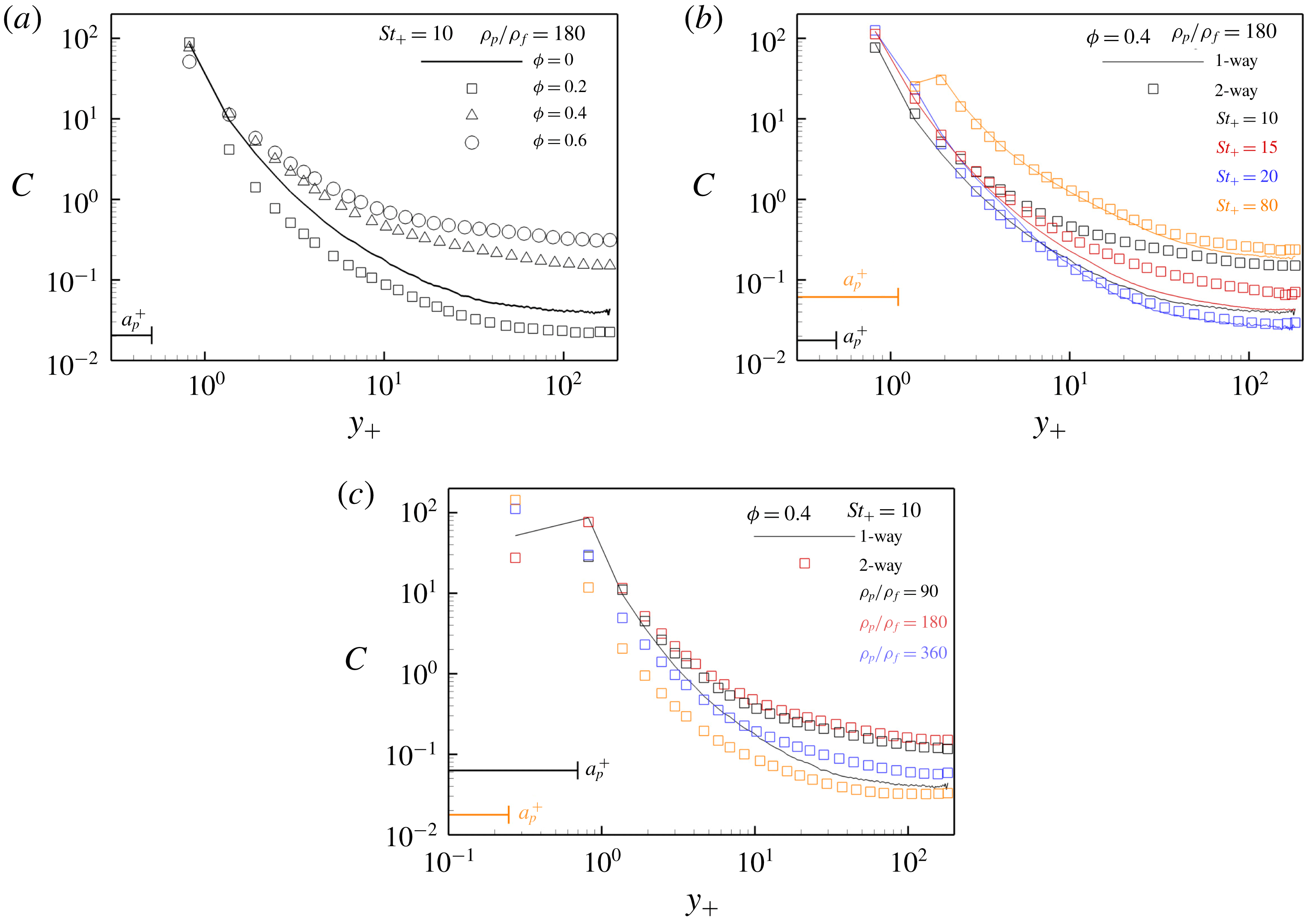
The particle mean distribution is presented in figure 10 as a function of the wall-normal distance. The particle concentration is defined as
 $C(r)=(n_{p}/\unicode[STIX]{x0394}V_{r})/(N_{p}/V_{f})$
, where
 $n_{p}$
is the number of particles in a cylindrical shell of volume
 $\unicode[STIX]{x0394}V_{r}=2\unicode[STIX]{x03C0}r\unicode[STIX]{x0394}rL_{z}$
placed at distance
 $r$
from the axis and
 $N_{p}$
is the total number of particles in the fluid domain
 $V_{f}$
. The normalisation of
 $C(r)$
is chosen such that
 $C=1$
when the particles are homogeneously distributed throughout the fluid domain. In the one-way coupling regime, inertial particles tend to segregate in the near-wall region. The preferential accumulation, i.e. turbophoresis (see Caporaloni et al. (Reference Caporaloni, Tampieri, Trombetti and Vittori1975), Reeks (Reference Reeks1983) and the review by Balachandar & Eaton (Reference Balachandar and Eaton2010)), is controlled by the Stokes number (see Marchioli & Soldati (Reference Marchioli and Soldati2002) and Sardina et al. (Reference Sardina, Schlatter, Brandt, Picano and Casciola2012a
) for the channel and the boundary layer, respectively). We have checked that the concentration profiles for the present simulations operated in the one-way coupling regime match the data reported by Picano, Sardina & Casciola (Reference Picano, Sardina and Casciola2009) in a spatially developing pipe flow, and by Sardina et al. (Reference Sardina, Picano, Schlatter, Brandt and Casciola2011) for a statistically steady pipe flow, by comparing the results when the flow has reached fully developed conditions (data not shown; F. Picano, personal communication). The question is whether the back-reaction and the resulting turbulent modification are able to alter the particle accumulation across the pipe.
Figure 10 addresses the effect of mass loading, Stokes number and density ratio. At low mass loading (
 $\unicode[STIX]{x1D719}=0.2$
) the particle concentration through the pipe decreases and particles segregate more at the wall. The opposite occurs when the mass loading increases. Concerning the Stokes number, the back-reaction is effective in modifying the particle concentration with respect to the uncoupled case only for the populations at
 $St_{+}=10$
and
 $St_{+}=15$
. Even at high Stokes number (
 $St_{+}=80$
), the particles are still unevenly distributed across the flow domain. In the previous section, negligible turbulence modification was seen for this Stokes number; therefore, accumulation of particles is not necessarily the only precursor for turbulence modification. Figure 10(c) addresses the effect of the density ratio. The solid line, representing the concentration in the one-way coupling regime, is the same for all cases since it only depends on the Stokes number. The trend of particle concentration in the bulk of the flow is not monotonic, the highest being at
 $\unicode[STIX]{x1D70C}_{p}/\unicode[STIX]{x1D70C}_{f}=180$
. The opposite behaviour is observed at the wall. Unlike the uncoupled case, the density ratio is a further crucial parameter in the two-way regime that influences the particle concentration.
Mean particle concentration
 $C$
against the wall-normal distance
 $y=(R-r)/y_{\ast }$
. The lines refer to the particle concentration in the uncoupled case whilst the symbols show the concentration in the two-way regime. The nominal particle radius is indicated with a horizontal line with the same colour code as the data in the plots. (a) Data at
 $St_{+}=10$
and
 $\unicode[STIX]{x1D70C}_{p}/\unicode[STIX]{x1D70C}_{f}=180$
and different mass loads:
 $\unicode[STIX]{x1D719}=0.2$
(▫),
 $\unicode[STIX]{x1D719}=0.4$
(▵) and
 $\unicode[STIX]{x1D719}=0.6$
(○). (b) Effect of Stokes number:
 $St_{+}=10$
(black),
 $St_{+}=15$
(red),
 $St_{+}=20$
(blue) and
 $St_{+}=80$
(orange). (c) Effect of the density ratio:
 $\unicode[STIX]{x1D70C}_{p}/\unicode[STIX]{x1D70C}_{f}=90$
(black),
 $\unicode[STIX]{x1D70C}_{p}/\unicode[STIX]{x1D70C}_{f}=180$
(red),
 $\unicode[STIX]{x1D70C}_{p}/\unicode[STIX]{x1D70C}_{f}=360$
(blue) and
 $\unicode[STIX]{x1D70C}_{p}/\unicode[STIX]{x1D70C}_{f}=560$
(orange).

5 Final remarks
A proper methodology to account for the inter-phase momentum exchange between inertial particles and the carrier flow in the presence of a wall has been developed. The approach extends the original ERPP method to account for the additional physics introduced by the wall. The disturbance generated by small particles can still be evaluated in a closed form by considering the associated unsteady Stokes problem in the half-space where only the impermeability boundary condition is enforced at the wall. When the disturbance is transferred to the background flow, the no-slip boundary condition is enforced by the Navier–Stokes solver of the carrier phase. From a physical point of view, this step corresponds to the generation and diffusion of the vorticity generated by the particles close to the wall. The approach has been carefully validated, showing how the impulse generated by the particles is correctly transferred to the fluid impulse in the bulk and to the viscous drag force at the wall. These results highlight the need to consider a set of images for those particles that lie close to the wall in order to reproduce the correct physics of the inter-phase momentum coupling.
The second part of the paper addresses the extended ERPP approach applied to direct numerical simulations of particle-laden fully developed turbulent pipe flow. The physical consistency of the inter-phase coupling method allows for a reliable analysis of the stress budget. In the near-wall region, the ERPP approach has been proven to capture the vorticity generated by the particles and the ensuing viscous shear stress. Results show a modification of the turbulent Reynolds shear stress and the important role played by the extra stress produced by the particles close to the wall. The physical interpretation corresponds to an augmented momentum flux towards the wall that ultimately increases the viscous shear stress and consequently the drag.
The approach applies to small particles, i.e. diameter comparable to the smallest hydrodynamical length scale of the flow. The disturbance must be described by the unsteady Stokes equations, i.e. the particle Reynolds number is small. The suspension is considered diluted since inter-particle collisions and hydrodynamic interactions are neglected. No limitations are placed on the density ratio, i.e. the approach can be used for either heavy particles or light bubbles. Clearly, in the latter case, added-mass and lift effects in the expression of the force on a bubble must be considered.
Acknowledgements
The research leading to these results has received funding from the European Research Council under the European Union’s Seventh Framework Programme (FP7/ 2007–2013)/ERC grant agreement no. (339446).