I. INTRODUCTION
With the development of industrial technology, it is difficult for single material to satisfy the increasing requirements of high strength and high toughness. For example, martensitic stainless steels with extremely high strength and hardness, but relatively less-ductile under an as-quenched condition have severe limits in its practical application,Reference Nambu, Michiuchi, Inoue and Koseki1 while the soft and ductile austenitic stainless steel just make up for this shortcoming. Recently, it was demonstrated that the rolling laminated composite plate combines its strength–ductility beyond these properties in conventional steels.Reference Seok, Lee, Lee, Ramamurty, Nambu, Koseki and Jang2
At present, there are many methods for manufacturing composite plates, such as explosive welding method,Reference Zhang, Wang, Zhang, Wei, Cao, Yan and Zhou3–Reference Bataev, Ogneva, Bataev, Mali, Esikov, Lazurenko, Guo and Jorge Junior5 electromagnetic casting method,Reference Wu, Kang, Chen, Liu and Wang6,Reference Dwivedia, Sharma and Mishra7 and so on. The rolling method is one of the most common methods for producing metal composite plates. The existing studies are mainly concentrated on the rolling of the aluminum matrix composite plate,Reference Springer, Kostka, Payton, Raabe, Kaysser-Pyzalla and Eggeler8–Reference Reihanian and Naseri11 copper matrix composite plate,Reference Ohaski, Kato, Tsuji, Ohkubo and Hono12–Reference Li, Zu and Wang14 magnesium matrix composite plate,Reference Wu, Chang, Maawad, Gan, Brokmeier and Zheng15–Reference Chang, Zheng, Gan, Xu and Brokmeier17 and titanium matrix composite plate.Reference Yang, Cizek, Hodgson and Wen9,Reference Baufeld, der Biest and Gault18,Reference Cui, Fan, Lin, Wang, Huang and Peng19 It has been reported that the roll bonding of metals is affected by various factors, such as rolling temperature,Reference Eizadjou, Manesh and Janghorban20–Reference Movahedi, Madaah-Hosseini and Kokabi22 rolling reduction,Reference Eizadjou, Manesh and Janghorban20–Reference Chaudhari and Acoff23 rolling speed,Reference Abbasi and Toroghinejad21,Reference Jamaati and Toroghinejad24 and annealing treatment.Reference Luo and Acoff25–Reference Lee, Han, Kim, Ryi and Kim29 The microstructure and mechanical properties of composite plates have been extensively studied. A great improvement of their fracture properties, such as bending toughness,Reference Pozuelo, Carreno, Caesi and Ruano30,Reference Liu, Huang, Rong, Geng and Yin31 impact resistance,Reference Pozuelo, Carreno, Caesi and Ruano30,Reference Pozuelo, Carreno and Ruano32 and fatigue properties,Reference Adharapurapu, Vecchio, Jiang and Rohatgi33 has been reported. Up to now, a wide range of light metal materials and rolling processes have been extensively studied to improve its performance and promote its application.
Except for the study on rolling laminated composite plate between light metals, multilayered steel (MLS) composite plate consisting of alternating ductile austenitic and brittle martensitic stainless steel layers is a new concept for material configuration as it offers excellent combinations of strength and ductility, which makes as-quenched martensitic steel become the possibility of fabricating high-strength structural components.Reference Seok, Lee, Lee, Ramamurty, Nambu, Koseki and Jang2 SeokReference Seok, Lee, Lee, Ramamurty, Nambu, Koseki and Jang2 found that the martensite volume fraction of the mid-thickness 301 layer increases with strain and the transformation priority appears in the region near the interfaces due to the existence of steeper strain gradient near the interfaces. InoueReference Inoue, Nambu, Ishimoto and Koseki34 showed that MLS (consisting of alternating ductile austenitic and brittle martensitic stainless steel) has excellent tensile strength, reaching 1.2 GPa and at the same time considerably ductile at least 15% failure strain. OyaReference Oya, Tiesler, Kawanishi, Yanagimoto and Koseki35 evaluated the bending formability of multilayered steel sheets by V-bending tests and hemming tests. The results imply that the strong interfaces of multilayered steel sheets can withstand severe bending deformation. NambuReference Nambu, Michiuchi, Inoue and Koseki1 demonstrated that tensile ductility could be markedly enhanced as the bonding strength increased.
The previous studies on improving the strength–ductility of the MLS composite plate mostly focused on the analysis of microstructure and properties and effects of heat treatment, and little attention was paid to the effect of layer thickness, especially in the martensitic/austenitic MLS composite plate. InoueReference Inoue, Nambu, Ishimoto and Koseki34 found that both the tensile strength and fracture elongation of the sheets increased systematically with the decrease of layer thickness. However, specific analysis about the layer thickness affecting its microstructure and properties is still scarce. SeokReference Seok, Lee, Lee, Ramamurty, Nambu, Koseki and Jang2 found that further enhancements in strength can be obtained by either incorporating even stronger constituents or by increasing the martensite content, or both. Therefore, there is still hope on playing with the hierarchy in controlling the layer thickness (and the part of the interface). KurmanaevaReference Kurmanaeva, McCrea, Jian, Fiebig, Wang, Mukherjee and Lavernia36 investigated the influence of layer thickness on mechanical properties of multilayered NiFe samples processed by electrodeposition, and discovered that with layer thickness decrease, the strength of the multilayer sample reached a maximum and remained relatively constant when the layer thickness was less than 100 nm. Based on above studies, layer thickness has important effect on mechanical properties of the multilayered composite plate. For our developed 2Cr13/316L MLS composite plates, the effects of rolling temperature on mechanical properties have been systematically investigated in Ref. Reference Cao, Zhao, Ding, Zhang, Jiang, Yan and Chen37; however, it is rare that the effect of the layer thickness on the microstructure and properties of the MLS composite plates, so it is very important to investigate the effect of rolling reductions on microstructure and properties of the 2Cr13/316L MLS composite plate by accumulative roll-bonding (ARB).
In this work, the 2Cr13/316L MLS composite plates consisting of alternating as-annealed martensitic steel and solution-annealed austenitic steel were fabricated by ARB at 1250 °C with reduction of 53, 72, and 82%. Here, the rolling processes of the MLS composite plates take advantage of the special manufacturing method of recycle heating. The relationship between the rolling reduction and microstructure and mechanical properties of the MLS composite plates will be investigated in detail. The tensile and bending tests were conducted to reveal the effect of the layer thickness on the microstructure and properties of the MLS composite plates. The fracture mode and bending morphology are further studied by SEM. The present study provides a reference for the preparation and application of the MLS composite plates.
II. MATERIALS AND EXPERIMENTS
A. Materials and rolling process
The experimental MLS composite plate is composed of martensitic stainless steel (2Cr13) in an as-annealed state and good ductile austenitic stainless steel (316L) in solution-annealed condition. Their chemical compositions and mechanical properties are listed in Table I.
Chemical composition and mechanical properties of constituent steels.

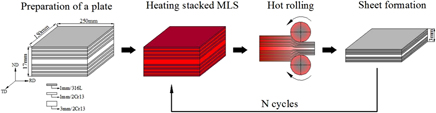
Figure 1 shows the schematic diagram of the rolling process of the 2Cr13/316L MLS composite plate. The steel sheets were cut into 250 × 150 × 1 mm3 and 250 × 150 × 3 mm3, polished with the wire brush to remove the surface oxide scale, and then washed the surface with alcohol and dried. The 316L and 2Cr13 sheets were stacked 15 layers in an alternating sequence. The 2Cr13 sheet with the thickness of 3 mm was placed in the middle as the middle layer and the 2Cr13 and 316L sheets with the thickness of 1 mm were placed alternately on both sides. And the 316L sheets were placed as the top and bottom layer of the whole MLS composite plate. The original thickness of stacked steel sheets is 17 mm before rolling. Subsequently, the stacked steel sheets were tightly fixed and welded around by TIG welding with a welding current of 100 A and a welding voltage of 10 V to prevent dislocation slip and interfacial oxidation between plates during the rolling process. Then the stacked steel sheets were placed in the muffle furnace and heated to 1250 °C for 40 min.
Schematic diagram of the rolling process of the 2Cr13/316L MLS composite plate (RD: rolling direction, ND: Normal direction, TD: Transverse direction).

The hot-rolling processes were further performed with a starting temperature at 1250 °C. Final thickness of laminates was ranged from 3 to 8 mm, depending on the target reduction of 53, 72, and 82%. The MLS composite plates under the 53% reduction (3 passes) were performed by 3-pass rolling. The MLS composite plates under the 72% reduction (3 + 4 passes) were manufactured by heating to 1250 °C for 15 min and rolling again for 4 passes on the base of the MLS composite plates under the 53% reduction. The MLS composite plates under the 82% reduction (3 + 4 + 3 passes) were also obtained by heating to 1250 °C for 15 min and rolling again for 3 passes on the base of the MLS composite plates under the 72% reduction. And all MLS composite plates were air cooled after hot rolling. To obtain accurate results, three sets of composite plates were rolled under each reduction, three sets of samples were taken for each composite plate, and a total of nine samples were tested for each test parameter.
B. Microstructure and fracture morphology
The microstructure and fracture morphology were measured by scanning electron microscopy (SEM; QUANTA FEG450, FEI, Hillsboro, Oregon). The specimens were cut from the 2Cr13/316L composite plates with different rolling reductions and then were grinded with sandpaper of 120#, 240#, 400#, 600#, 800#, 1000#, 1500#, and 2000#, polished, and then etched in a solution of HNO3:HCL:H2O = 1:3:3 for 30–60 s. The interface element diffusion was measured by using an X-ray energy-dispersive spectrometer (EDS).
C. Hardness
To reveal the hardness change of different layers for the 2Cr13/316L MLS composite plates under different rolling reductions, the Vickers microhardness was measured by using an HVT-1000A automatic hardness instrument, Huayin Testmart, Yantai, China (load 50 g, dwell time 15 s).
D. Tensile tests
The tensile specimens were machined into flat dog-bone shape with a gauge length of 50 mm and thickness of 3 mm, 5 mm and 8 mm, respectively. The tensile tests were conducted at the ambient temperature with an engineering strain rate of 1.0 × 10⁻³ s−1 in the gauge section. The extensometer was used for measuring its elongation more accurately during the tensile process.
E. Bending tests
The bending specimens were cut into a rectangular body with the size of 100 × 10 × 3 mm3, 100 × 10 × 5 mm3, and 100 × 10 × 8 mm3, respectively. The bending experiments were conducted to investigate the formability of the 2Cr13/316L MLS composite plates. Three-point bending tests were conducted with bending angles of 130° (±2°) and 180°. To further observe the deformation of the specimens during the bending process, the cross section of the bending specimen was polished and etched before bending so that the microstructure and fracture condition were observed after bending to a certain angle by scanning electron microscopy (SEM; QUANTA FEG450).
III. RESULTS AND DISCUSSION
A. Effect of the rolling reduction on microstructure
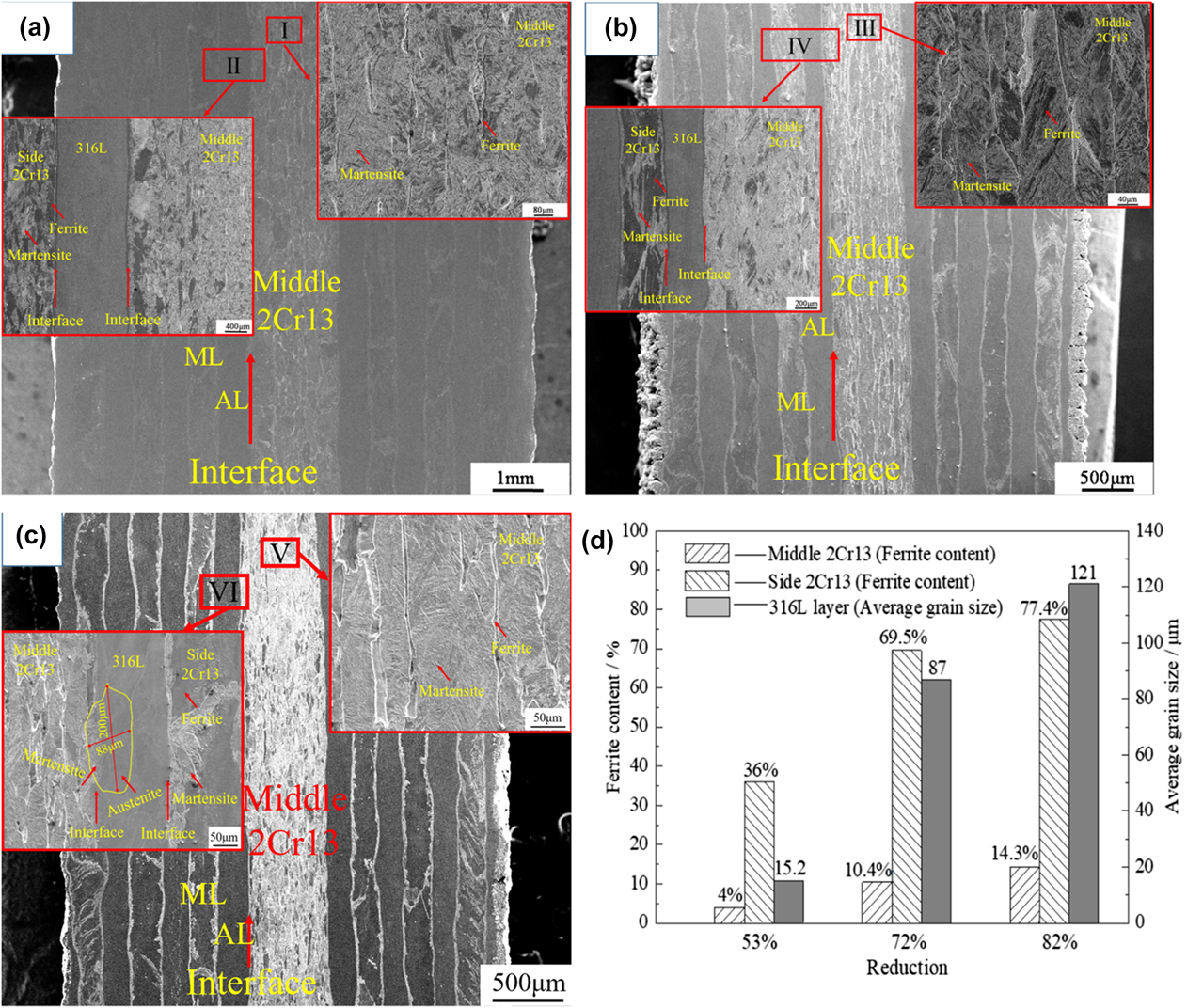
Figure 2 shows the microstructure and the histogram of ferrite content in the 2Cr13 layer and grain size in the 316L layer of the 316L/2Cr13 MLS composite plates under different rolling reductions of 53% (3 passes), 72% (3 + 4 passes), and 82% (3 + 4 + 3 passes), respectively. The thickness of each layer decreases with the increase of the reduction from 53% to 82%. With the increase of the reduction from 53% to 82%, the thicknesses of the middle 2Cr13 layer, both side 316L layer and both side 2Cr13 layer decrease from 1418 μm to 599 μm, from 468 μm to 172 μm and from 474 μm to 175 μm, respectively. In addition, it has been proved that the rolling reduction of the 2Cr13 layer is different from that of the 316L layer because the deformation resistance of the 2Cr13 is larger than that of 316L during a given rolling condition.
Microstructure (a–c) and histogram (d) of ferrite content in the 2Cr13 layer and grain size in the 316L layer of the 316L/2Cr13 MLS composite plates under different reductions (a) 53%, (b) 72%, and (c) 82% (ML: martensitic layer, AL: austenitic layer).

From the macrostructure and interface of the 2Cr13/316L MLS composite plates under different reductions of 53, 72, and 82% in Fig. 2, it can be found that the interfaces between the martensite layer (ML) and the austenitic layer (AL) are flat and uniform under the 53% reduction [Fig. 2(a)], while the interfaces become zigzag and a “wave like” structure with a reduction of 72% [Fig. 2(b)]. When the reduction increased to 82%, the interfaces between the 316L layer and 2Cr13 layer which include the middle and both side 2Cr13 layer become curved and necking appears in parts of the region [Fig. 2(c)].
From the microstructure of the middle 2Cr13 layer of the 2Cr13/316L MLS composite plates under different reductions of 53, 72, and 82% in Fig. 2, it can be seen that the middle 2Cr13 layer is mainly composed of lath martensite and a small amount of ribbon-like ferrite along the rolling direction, which looks like “gully” shape in region I. The ferrite bands are distributed obviously along grain boundaries for the specimen under the 72% reduction in region III and ferrite grains are coarse and continuous distributed around the martensite phase in region V when the reduction increased to 82%. The content of ferrite in the middle 2Cr13 layer increased from 4 to 14.3%, as shown in Fig. 2(d).
From the magnification figure of regions II and IV in Fig. 2, it can be found that ferrite grains in both side 2Cr13 layers are elongated along the rolling direction and ferrite content in both side 2Cr13 layers is more than that of the middle 2Cr13 layer. Figure 2(d) shows the histogram of ferrite content in the 2Cr13 layer and grain size in the 316L layer of the 316L/2Cr13 MLS composite plates under different reductions of 53%, 72%, and 82%, respectively. As shown in Fig. 2(d), with the increase of reduction, ferrite grains grew up gradually and the content of ferrite in the side 2Cr13 layer increased from 36 to 77.4%. Most ferrites are distributed in the center of the 2Cr13 layer, which is related to the elemental diffusion caused by the repeat heating. The average grain size of the 316L layer is 15.2 μm, 87.0 μm, and 121.0 μm, respectively. Ferrites in the side 2Cr13 layer become flake shape along the rolling direction while the distribution of martensite also becomes irregular.
As shown in region VI of Fig. 2(c), it can be found that the common grain was formed at the interface between the middle 2Cr13 layer and 316L layer. It may be related to the diffusion of the elements during the heating of the MLS composite plates so that the elements at the interface are different from that of the matrix structure. However, the interface mechanism of common grain formation remains further studied. According to Tong,Reference Tong, Chen, Bao, Yan and Ren38 the formation of eutectic is related to the mechanism of temperature-induced recrystallization. The higher rolling temperature increases atomic energy, which make atoms at the interface become active. These contribute to the growth of the new grain nucleus and recrystallization at the interface. Finally, eutectic and solid solution were formed due to the rearrangement of different crystal orientations on both sides of the MLS composite plates under plastic deformation and thermal diffusion effect.
The grain sizes of the MLS composite plates increase with the increase of the reduction, which is different from the previous research.Reference Ma, Huo, Liu, Wang and Wang39,Reference Zhou, Kong, Wu, Wang and Chen40 The different research result is caused by the different rolling methods. During the rolling process, the MLS composite plate is further recycled to heat to 1250 °C and maintaining high temperature increases the driving force of grain growth. The increase of the reduction made the grain break and increased the nucleation point, but it is not enough to compensate the grain growth at high temperature. It can be seen from the above figures that contents of ferrite increase with the increase of reduction, which ferrites were mostly distributed in the center of the 2Cr13 layer on both sides. The ferrite is elongated along the rolling direction which is the same as in the work of KimuraReference Kimura, Ushioda, Ishimaru and Takahashi41 and martensite was mostly produced at the interfaces.
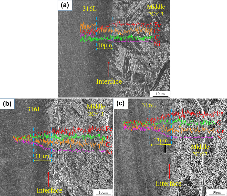
Figure 3 shows the EDS analysis at the interface of the MLS composite plates under different reductions of 53, 72, and 82%. From Fig. 3, the diffusion trend of the elements of Fe, Cr, Ni, and C can be found at the interface, especially under the 82% reduction. The Fe and C elements diffused from the 2Cr13 layer to the 316L layer. By contrast, the Cr and Ni elements diffused from the 316L layer to the 2Cr13 layer. At this time, the transition layer with a certain width of the element diffusion gradient was formed at the interface, but it was not obvious on the micromorphology.
EDS analysis of MLS composite plates under different reductions, (a) 53%, (b) 72%, and (c) 82%.

With the increase of the reduction from 53 to 82%, the diffusion of the elements improved and the thickness of the transition layer correspondingly increased from 10 to 13 μm, which is same as Ma.Reference Ma, Huo, Liu, Wang and Wang39 A main reason is that large deformation increases crystal defects and enhances thermodynamic energy, resulting in easier migration and diffusion of atoms. Another reason is the contribution of reheating at high temperature.
The difference of temperature, deformation quantity, and content of C elements respectively induces the formation of martensite and ferrite phases. The higher the carbon content is, the easier it is to form martensite, and the opposite is easy to form ferrite. Compared with the middle 2Cr13 layer, the heating rate of both side 2Cr13 layers is faster, and the deformation amount is larger during the rolling process. Therefore, the C element on both side 2Cr13 layers diffuses more sharply to the adjacent 316 layers than that of the middle 2Cr13 layer, and the C element loss on both side 2Cr13 layers is also large, which leads to more ferrite and less martensite on the both side 2Cr13 layers than that of the middle 2Cr13 layer, as shown in Fig. 2. And LiuReference Liu, Li and Ma42 found that the diffusion of the Ni element improved the hardenability of martensitic stainless steel. The oxidation and loss of Mn led to the decrease of the austenite phase region and the increase of the martensitic transformation point M s so that more martensite may be formed at the interface of the 2Cr13 layer.
B. Effect of reduction on mechanical properties
1. Effect of reduction on hardness
It is known from the above analysis that the microstructure of each layer of the 2Cr13/316L MLS composite plates is different. To more accurately express the hardness of the MLS, the hardness distribution of the MLS composite plates can be analyzed by the hardness of the different microstructures on different layers.
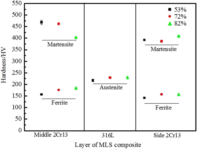
Figure 4 shows the microhardness distribution of the 2Cr13/316L MLS composite plates under different reductions. It can be seen that the hardness of martensite in the middle 2Cr13 layer decreases with the increase of the total rolling reduction. Ferrite content in the middle 2Cr13 layer increased with rolling reduction because of the solid solution of the Cr element in ferrite phases and the diffusion of C elements, which affect the hardness of the martensite microstructure. According to Hall–Petch formula, the grain sizes increased with the increase of reheating times, which make hardness decline. The hardness of the 316L layer does not change much. The hardness of the austenite is determined by both deformations, strengthening and grain coarsening. The austenite grain growth caused by reheating under the large reduction, resulting in a decrease in hardness of the 316L layer, while work hardening during the rolling process increases the hardness of the 316L layer. These two opposite effects lead to little change in the hardness of the 316L layer.
Microhardness distribution of the 2Cr13/316L MLS composite plates under different reductions.

The hardness of the 2Cr13 layer on both sides is determined by the hardness of martensite and ferrite. It can be seen that the hardness of martensite on both side 2Cr13 layer has little change under various reductions. For the MLS composite plates under the reduction of 53 and 72%, the hardness of martensite on both side 2Cr13 layer is much lower than that of the middle 2Cr13 layer, which mainly related to the ferrite content in the 2Cr13 layer. As shown in Fig. 2(d), the ferrite content in the middle 2Cr13 layer is much lower than that of the side 2Cr13 layer. When the reduction increased, the hardness increased with the increase of deformation strengthening. However, the hardness is decreased by the growth of grains and the increase of ferrite content, which are also crucial factors that cannot be ignored. The two factors jointly determined the hardness of the 2Cr13 layer. The hardness of the ferrite of the 2Cr13 layer on both sides decreases with the increase of the reduction, which is in accordance with the previous explanation.
2. Effects of reduction on tensile strength
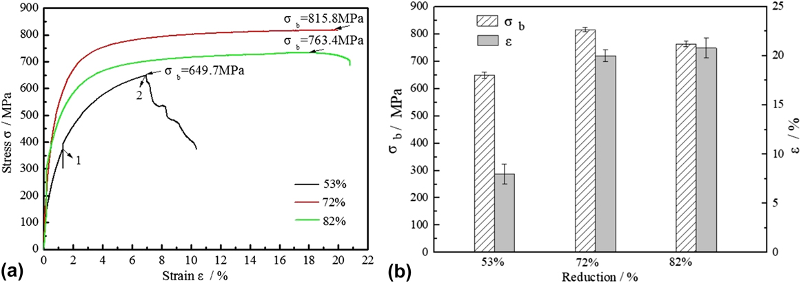
Figure 5 presents the engineering stress–strain curves and the histogram of tensile strength and elongation of the 2Cr13/316L MLS composite plates under different reductions. As can be seen in Fig. 5, with the increase of the total rolling reduction, the tensile strength increased first and then decreased. When the reduction of the MLS composite plate is 53%, the tensile strength and elongation are 649.7 MPa and 8.2%, respectively, which is lowest than that of 72 and 82%. Although ferrite content in middle and both side 2Cr13 layer and grain size under the 53% reduction are small, delamination cracking may occur at the middle interface due to a small amount of reduction during the stretching process. According to Nambu,Reference Nambu, Michiuchi, Inoue and Koseki1 the interfacial bonding strength and layer thickness ratio seriously affect the tensile strength and ductility of the composite plate. When the interfacial bonding strength is high, the MLS composite plates tend to have higher strength and ductility. The MLS composite plate under the 53% reduction may have low tensile strength and elongation due to insufficient interfacial bonding strength. The tensile strength of the MLS composite plate under the 82% reduction is lower than that under the 72% reduction, which is mainly due to the formation of a large number of “gully” strip ferrite in the middle layer, the increase of ferrite content on both side 2Cr13 layer, and the coarser of the grain size of austenite in 316L. Therefore, the MLS composite plate under the 72% reduction has high tensile strength (815.8 MPa) and elongation (about 20%), showing good tensile properties.
Engineering stress–strain curves (a) and histogram of tensile strength and elongation (b) of 2Cr13/316L MLS composite plates under different reductions.

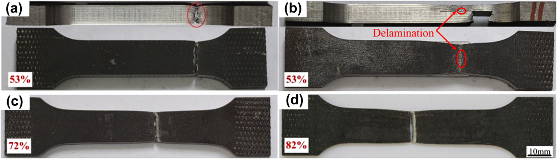
Figure 6 shows the macroscopic tensile morphology of the 2Cr13/316L MLS composite plates under different reductions. It can be found that necking occurred at both reductions of 72 and 82%, while both fracture modes of necking and delamination phenomenon occurred under the 53% reduction. As shown in Fig. 6(a), the interfacial bonding is relatively good. From the side of the sample (shown in red circle), it can be seen that the necking occurred at fracture position and the sides of the MLS composite plates shrank much larger than the middle layer. This is because the middle 2Cr13 layer consists of a large amount of martensite and a few of ferrite, which leads to more cleavage fracture during tensile test. The tensile curve of the 53% reduction has a sudden decrease in position 1 in Fig. 5(a). At this point, with further loading, the delamination and crack appears at the cross section of the tensile specimen [the place indicated by the red arrows in Fig. 6(b)], and the phenomena can be observed by tensile processes. The layer between middle 2Cr13 and the both side layers with better interlayer bonding appeared stratification when the curve reached position 2 of the curve under the 53% reduction in Fig. 5(a). It can be seen that the combination in the interface is good, which means a good plasticity between side layers. The significant necking occurred on both side layers before specimen fracture. It can be verified in the following fracture analysis. Combined the analysis of Figs. 5 and 6, the interface bonding quality of the MLS composite plates is unstable due to the lack of reduction under the 53% reduction. As can be seen from Figs. 6(c) and 6(d), the specimens have been fractured within the gauge range and local necking phenomenon appeared at the fracture site. There was no macroscopic cracking along the tensile direction. It can be concluded that MLS composite plates under both reductions of 72 and 82% have better connecting quality when other conditions are consistent.
Macroscopic tensile morphology of the 2Cr13/316L MLS composite plates under different reductions, (a), (b) 53%, (c) 72%, and (d) 82%.

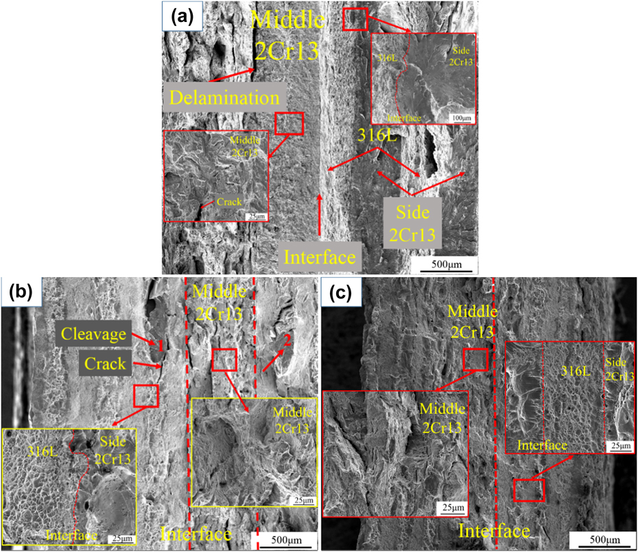
Figure 7 shows the macroscopic and microscopic fracture morphology of the 2Cr13/316L MLS composite plates under different reductions of 53, 72, and 82%. From the macroscopic fracture morphology in Fig. 7(a), it can be seen that a clear interface delamination crack appeared between the middle 2Cr13 layer and 316L layer, which leads to the macroscopic delamination phenomenon of the cross section of the tensile specimen in Fig. 6(b), and seriously affects its tensile strength and elongation of the MLS composite plate under the 53% reduction. For the MLS composite plate under the 72% reduction, the partial cleavage (red arrows 1 and 2) and cracking of the 2Cr13 layer on both sides are shown in Fig. 7(b), and the dimples fracture dominated the whole fracture. From the macroscopic fracture morphology in Fig. 7(c), it can be seen that the larger deformation is produced in the MLS composite plate under the 82% reduction.
Macroscopic and microscopic fracture morphology of 2Cr13/316L MLS composite plates under different reductions, (a) 53%, (b) 72%, and (c) 82%.

The further enlargement of the macroscopic fracture morphology of the middle 2Cr13 layer under different reductions is shown in the small figure in Fig. 7. From the fracture features of the middle 2Cr13 layer in Fig. 7, it can be seen that the cleavage fracture occurred in the middle 2Cr13 layer for the MLS composite plate under the 53% reduction, while for the MLS composite plates under 72 and 82% reductions, mostly dimples and a few cleavage fractures dominated the fracture of the middle 2Cr13 layer. It is also the reason why the tensile strength and elongation of the MLS composite plates under 72 and 82% reductions are better than that under 53% reduction.
The fracture morphology at the interface between 316L and 2Cr13 layers on both sides under different reductions is shown in the small figure in Fig. 7. As can be seen from the interface in Fig. 7, the cleavage fracture with obvious river pattern dominated the fracture of both side 2Cr13 layers for the MLS composite plate under the 53% reduction. With the increase of the reduction, dimple fracture becomes the main fracture mode in the 2Cr13 layers on both sides, which indicates that the satisfied interfacial bonding can be achieved. The main reason is that ferrite content increases with the increase of the reduction, which controls the fracture modes of the both side 2Cr13 layers. Under the 72% reduction, a transition layer with a certain thickness can be formed at the interface, as discussed in Fig. 3, which means that the better combined interface can be achieved.
3. Effects of reduction on bending strength
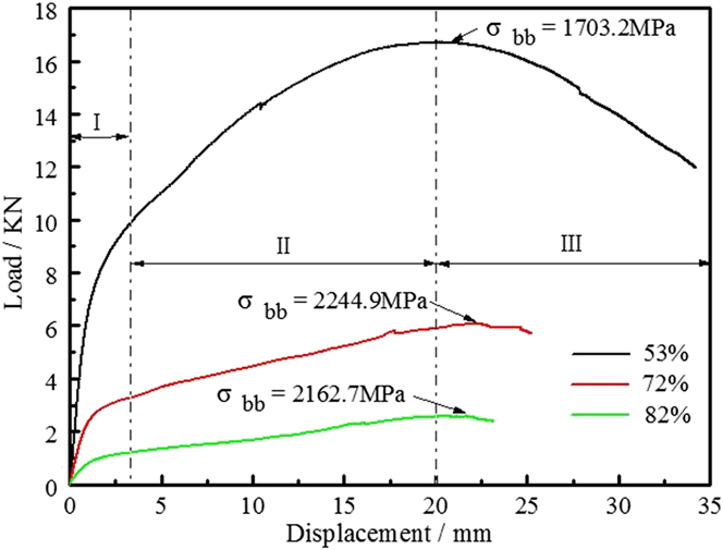
Figure 8 shows the load–displacement curves of the 2Cr13/316L MLS composite plates bending to 130° under different reductions. The bending curves of the 2Cr13/316L MLS composite plates can be divided into three stages, the elastic section I, the nonlinear yield stage II, and the failure stage III, respectively. From the bending curves in Fig. 8, it can be found that the 2Cr13/316L MLS composite plate under the 53% reduction has larger bending force and larger displacement, which is actually related to the thicker and larger size of the specimen. However, it does not mean that it has a higher bending strength. It can be seen in Fig. 8 that the MLS composite plate has the highest bending strength of 2244.9 MPa at the reduction of 72%, while the composite plate under the 53% reduction has the lowest bending strength of 1703.2 MPa, which is consistent with the result of tensile strength. This is mainly related to the content of ferrite, the size of grain, and the interfacial bonding quality of the MLS composite plates under different reductions.
Load–displacement curves of the 2Cr13/316L MLS composite plates under different reduction bending to 130°.

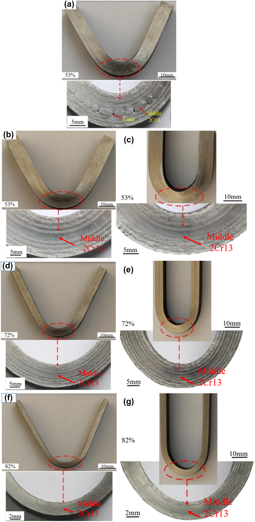
Figure 9 shows the macroscopic bending morphology of the 2Cr13/316L MLS composite plates bending to 130° and 180° under different reductions. The magnified views of the bending area indicated by the red circle of the corresponding sample were shown at the bottom. By comparing the bending morphology of the MLS composite plate bending to 130° under the 53% reduction in Figs. 9(a) and 9(b), it can be found that at the same reduction, the local cracks were produced only in the middle 2Cr13 layer of the bending specimen in Fig. 9(a), but there is no crack in the interface and layers of the bending specimen in Fig. 9(b). This further verifies the instability of the performance of the MLS composite plate at 53% reduction. It is consistent with the macrofracture feature in Figs. 6(a) and 6(b). No crack was formed on the outermost side of the two bending specimens, but a large amount of plastic deformation was occurred on both sides. However, for the composite plates under 72 and 82% reductions, no interfacial delamination or intralayer fracture were found during bending, which means that the MLS composite plates under 72 and 82% reductions have better mechanical properties, as shown in Figs. 9(d) and 9(f). Similarly, it can be found that no crack was formed under the reductions of 72 and 82% when the MLS composite plates were bent to 180°, as shown in Figs. 9(e) and 9(g). It should be noted here that some specimens at 53% reduction still do not produce visible cracks and delamination in the interface when they were bent to 180°, as shown in Fig. 9(c), which is enough to explain the instability of the performance of the MLS composite plate under the 53% reduction.
Macroscopic bending morphology of the 2Cr13/316L MLS composite plates under different reduction bending to 130° (a), (b) 53%, (d) 72%, (f) 82% and 180° (c) 53%, (e) 72%, and (g) 82%.

IV. CONCLUSIONS
This article mainly investigated the effect of different reductions on the microstructure and mechanical properties of the 2Cr13/316L MLS composite plates at the hot rolling temperature of 1250 °C. The main conclusions are summarized as follows:
(1) The middle 2Cr13 layer is mainly composed of martensite and a small amount of band ferrite. The 316L layers consist of austenite, and the 2Cr13 layers on both sides are composed of martensite and many ferrites. The content and grains size of ferrite increases with the increase of the reduction, which is related to the number of reheating.
(2) The hardness of the middle 2Cr13 layer decreases with the increase of reduction due to the increase of ferrite content in the middle 2Cr13 layer. The hardness of the 2Cr13 layers on both sides is determined by the hardness of martensite and ferrite. The hardness of martensite of the 2Cr13 layers on both sides has little change under various reductions and the hardness of ferrite of the 2Cr13 layers on both sides decreases with the increase of the reduction due to the coarse grains.
(3) The performance of the MLS composite plate under the 53% reduction is unstable and the delamination and cracks were formed in tensile test and bending test. However, there were no cracks and delamination when the MLS composite plates under 72 and 82% reductions were bent to 130° and 180°, which means the better interfacial bonding. The tensile strengths of the MLS composite plates under 72% and 82% reduction reached 815.8 MPa and 763.4 MPa, while the elongations were 20% and 20.8%, respectively. With the increase of the reduction, the fracture mode was also changed from cleavage fracture to dimple fracture.
ACKNOWLEDGMENTS
This work was financially supported by National Nature Science Foundation of China (Nos. 51761027 and 51675255), Foundation of Longyuan Innovation Teams of Gansu Province (2017-121), The Program of Innovation Groups of Basic Research of Gansu Province (17JR5RA107), The Foundation of Collaborative Innovation Teams in College of Gansu Province (2017C-07), Ningxia Hui Autonomous Region (Nature Science Foundation: No. NZ16049), and Ningxia High School Scientific Research Project (Excellent Young Teacher Training Fund Project: No. NGY2017016).