Introduction
We fly safe airplanes, enjoy the comfort of fast trains, and live in houses powered by wind turbines. These and many other structural applications that employ advanced composite materials are now part of our daily lives. The materials required for these applications must be able to withstand high stresses and serve for decades without failure. Because of increased concerns with air pollution and global warming, additional restrictions on efficiency and environmental impact have to be respected. In the language of engineers, these structural materials must be light, stiff, strong, and durable.
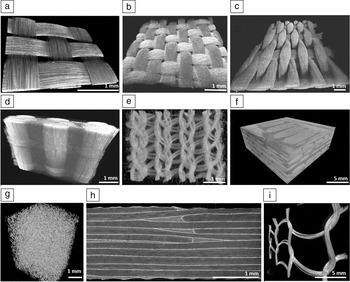
Fiber-reinforced polymer composites and, specifically, carbon fiber-reinforced plastic (CFRP) have been shown to outperform other materials in combining all of these properties. This is evidenced by their significant use in aerospace applications; Reference Harris, Starnes and Shuart1,Reference Fratzl and Weinkamer2 ∼50% of the structural mass of the newest airplanes is comprised of such advanced composites. These materials take advantage of the high specific stiffness and strength of microscale continuous fibers, and a compliant polymer matrix, both of which are also lightweight. The typical density of CFRP is about 1.6 g/cm3. The microfibers can be layered, woven, braided, knitted, or randomly assembled into a variety of mesolevel morphologies ( Figure 1 ) that allow tailoring of composite performance for different applications.
Diversity of reinforcement architectures on the mesolevel from 3D microcomputed tomography visualizations. (a) Carbon fiber plain weave (unit cell size 2.5 mm × 2.5 mm); (b) flax fiber twill weave (unit cell size 2.6 mm × 2.6 mm); (c) alumina fiber quasi-unidirectional weave (unit cell size 0.84 mm × 2.0 mm); (d) 3D woven glass weave (unit cell size 3.6 mm × 3.8 mm); (e) glass fiber knit (loop spacing 1.2 mm); (f) noncrimp carbon fiber composite (fiber bundle width 5.0 mm); (g) random steel fiber assembly (fiber diameter 8 µm); (h) carbon fiber laminate produced by automated tape placement (thickness of a ply ∼0.2 mm); and (i) open glass fiber knit (loop spacing 5.5 mm).

The vision for the next generation of composite materials is that they will be hierarchically designed down to the nanoscale. The importance of nanoscale features has long been recognized from studies of biological materials, which are all truly multiscale composites. Reference Fratzl and Weinkamer2–Reference Ortiz and Boyce4 In addition to using a plethora of different materials, nature also employs structural hierarchy to target multiple properties at the same time, which cannot be otherwise achieved (i.e., both high strength and high toughness). With the discovery of nanomaterials like carbon nanotubes (CNTs) and graphene, it is now possible to take the first steps toward hierarchical designs in man-made materials. Nanoengineering promises structural composites with superior mechanical properties as well as new functionalities. This review focuses on opportunities and challenges for polymer-based hierarchical composites of high stiffness, strength, and toughness enabled by CNTs.
Tubular nano-sized carbon filaments were reported more than six decades ago. Reference Radushkevich and Lukyanovich5,Reference Oberlin, Endo and Koyama6 It was not until Iijima’s report on CNTs in 1991 Reference Iijima7 that the composites community began intensively exploring CNTs. Interest in CNTs as reinforcement of polymers is due to their high stiffness (1 TPa) and strength (on the order of 50 GPa), Reference Yu, Files, Arepalli and Ruoff8 both of which are superior to those of existing carbon fibers (∼200–800 GPa)—the most advanced fibers available today. Moreover, high failure strain (12%) Reference Yu, Files, Arepalli and Ruoff8 has been reported for multiwall CNTs, promising structural composites with some ductility.
However, after 25 years of intensive research, Reference Coleman, Khan, Blau and Gun’ko9,Reference Spitalsky, Tasis, Papagelis and Galiotis10 it is now clear that CNT addition to polymers as fillers does not lead to nanocomposites that can compete with carbon fiber-reinforced polymers in mechanical performance. This is despite the exceptional stiffness and strength of CNTs. The dispersion route currently employed and other processing challenges limit achievable volume fractions and do not allow unidirectional alignment of the nanoreinforcement. Other technologies are on the rise where these difficulties are currently being addressed (see the section on CNT fibers).
In parallel with the previously discussed developments, CNTs have also been explored as a second reinforcing fiber in composites to complement existing (micro)fibers. Reference Siochi and Harrison11,Reference Lozano, Wardle, Moloney and Rawal12 Conventional laminated composites are susceptible to damage in the form of matrix cracks and delaminations (particularly under impact). This damage is highly undesirable as it limits the composite’s residual performance, including compressive strength and fatigue life. The benefit of CNTs is seen in targeting these long-standing challenges in composite performance. CNT integration can be grouped into the following three strategies: (1) deposition on fiber and ply surfaces; (2) dispersion in the matrix; and (3) integration in the fibers.
Over the years, there have been several reviews Reference Thostenson, Ren and Chou13–Reference Qian, Greenhalgh, Shaffer and Bismarck15 and books Reference Koo16,Reference Loos17 written on hierarchical composites with CNTs. We present some of the success stories and remaining challenges in these developments, with a focus on polymer-based hierarchical composites with high stiffness, strength, and toughness enabled by CNTs.
Interface nanoengineering
Interfaces in composites are a key to engineering synergistic properties—properties that go beyond those that are brought by the two constituents (fibers and matrix). Composite properties such as compressive strength, impact resistance, fatigue life, and fracture toughness are sensitive to the performance of the fiber/matrix interface. The strength and toughness of the interface require proper tuning to achieve overall optimal performance of the composite. Fiber debonding and pullout are important energy-dissipating mechanisms that can be exploited for improving composite toughness.
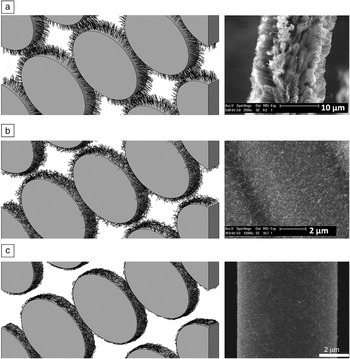
The use of CNTs in composites presents many opportunities for interface engineering. In the literature, two routes are distinguished: (1) direct growth of CNTs on fibers or plies using the chemical vapor deposition (CVD) process and (2) application of already synthesized CNTs using sizing or coating technologies ( Figure 2 ). Reference Kamae and Drzal18 Fibers with grown CNTs are also known as “fuzzy” fibers. Reference Yamamoto, Hart, Garcia, Wicks, Duong, Slocum and Wardle19 The direct growth of CNTs offers advantages over other methods. With this approach, much higher CNT loadings (10–100 times higher than by mixing) in the composite can be achieved. Also, challenges related to CNT agglomeration, filtration, and increase in matrix viscosity are common in the dispersion route, but are not present in composites with the fuzzy fibers. There are additional benefits, such as the possibility to control CNT alignment. For example, it is feasible to grow radially oriented CNTs on a fiber surface. Reference Garcia, Hart, Wardle and Slocum20–Reference Wicks, Wang, Williams and Wardle22 The radial alignment offers substantial benefits in terms of stiffening, strengthening, and toughening of the fiber/matrix interface, Reference Qian, Bismarck, Greenhalgh, Kalinka and Shaffer23–Reference Thostenson, Li, Wang, Ren and Chou27 which has an impact on macroscopic properties, such as interlaminar shear strength, interlaminar toughness, and composite strength. According to modeling studies, CNT forests on fibers suppress stresses at the interface, Reference Romanov, Lomov, Verpoest and Gorbatikh28,Reference Romanov, Lomov, Verpoest and Gorbatikh29 allowing for a delay in damage onset.
Microfibers with carbon nanotube (CNT) modified surfaces. (a) Radially aligned CNT growth; (b) randomly oriented CNT growth; and (c) CNTs deposited in a sizing. Left column: simulated configurations (diameters of fibers and nanotubes are 7 µm and 9 nm, respectively) and right column: scanning electron microscope images of practically realizable configurations. Reference Romanov, Lomov, Verpoest and Gorbatikh29 Reproduced with permission from Reference Reference Kamae and Drzal18. © 2012 Elsevier.

CVD deposition of CNTs on fibers and plies is not without its challenges. One such challenge is degradation of the carbon fiber strength after the CNT growth. Reference Qian, Bismarck, Greenhalgh, Kalinka and Shaffer23–Reference Zhang, Wang, He, Wang and Ren25 The decrease has been reported to be as much as 50% in strength, attributed to damage on the fiber surface introduced by the catalyst particles required for the CVD process. This challenge has persisted over the years, but due to significant research efforts, it has now been addressed, and CNT growth on carbon fibers with preserved fiber performance has been successfully carried out by several research teams. Reference Naito, Yang, Tanaka and Kagawa30–Reference Li, Lachman, Florin, Wagner and Wardle32 Producing “fuzzy” fiber composites with existing processing routes remains an open area of investigation. There is a need to better understand effects of the CNT fuzz on permeability, formability, and compressibility of the reinforcement, as changes in the reinforcement behavior may require adjustment of processing conditions. Reference Lomov, Gorbatikh, Houlle, Kotanjac, Koissin, Vallons and Verpoest33–Reference Lomov, Wicks, Gorbatikh, Verpoest and Wardle36
Localization of CNTs at interfaces can also be done via sizing or coating routes. The surface of fibers is treated (sized) for various reasons, for example, to improve their handleability or compatibility with the polymer. In this case, CNTs do not introduce damage to the fiber surface and, therefore, do not degrade the strength of the fibers. In contrast, CNT-reinforced sizings are known for their healing effects on surface defects. For glass fibers, this healing results in higher fiber strengths in comparison to fibers not sized. Reference Gao, Mäder and Plonka37,Reference Zhang, Zhuang, Liu, Mader, Heinrich and Gao38 CNT-modified sizings have also been shown to strengthen the fiber/matrix interface Reference Godara, Gorbatikh, Kalinka, Warrier, Rochez, Mezzo, Luizi, van Vuure, Lomov and Verpoest39,Reference Drescher, Thomas, Borris, Riedel and Arlt40 and improve composite properties that are interface controlled. This approach is more readily scaled up from a laboratory to industrial scale.
The interlaminar interface is another critical interface in composites. It can be strengthened and toughened by positioning CNTs in between laminate layers. This can be done either via the direct CNT growth route or sizing/coating technologies. Different levels of property improvement have been practically realized. Reference Qian, Greenhalgh, Shaffer and Bismarck15,Reference Veedu, Cao, Li, Ma, Soldano, Kar, Ajayan and Ghasemi-Nejhad41 Aligned CNTs are most effective as they lead to fracture toughness improvement of up to 2–3 times. Reference Garcia, Wardle and Hart42 In one study, CNTs in thermoplastic interlayer films provided up to a 30% increase in the residual laminate strength after impact. Reference Xu, Zhou, Hei, Zhang, Bao and Chen43 The main mechanism claimed to be responsible for these improvements is the pulling out of CNTs upon crack propagation through the material. CNTs have a high surface area, therefore, their debonding from the matrix is an efficient source of energy dissipation. Theoretical models predict toughness improvements by two orders of magnitude in comparison with conventional carbon fibers. Reference Wagner, Ajayan and Schulte44 Other mechanisms like crack deviation, crack pinning, and plastic deformation of the matrix have also been suggested. Reference Fiedler, Gojny, Wichmann, Nolte and Schulte45,Reference Quaresimin, Schulte, Zappalorto and Chandrasekaran46
Matrix nanoengineering
The toughness of fiber-reinforced composites is sensitive to the performance of the matrix. Stronger and tougher matrices lead to composites with higher resistance to matrix cracking and delaminations. Randomly oriented CNTs (implemented as matrix nanofillers) have been noted to increase, sometimes substantially, matrix-dominated properties of laminates, including the threshold for the onset of transverse cracking, Reference De Greef, Gorbatikh, Godara, Mezzo, Lomov and Verpoest47,Reference Yokozeki, Iwahori and Ishiwata48 interlaminar fracture toughness, Reference Godara, Mezzo, Luizi, Warrier, Lomov, VanVurre, Gorbatikh, Moldenaers and Verpoest49,Reference Tsantzalis, Karapappas, Vavouliotis, Tsotra, Kostopoulos, Tanimoto and Friedrich50 and fatigue life. Reference Qian, Greenhalgh, Shaffer and Bismarck15,Reference Grimmer and Dharan51–Reference Lubineau and Rahaman54 The range of improvements varies greatly—from a few to hundreds of percent. The compressive strength after impact has been much more difficult to improve even when matrix performance and interlaminar fracture toughness have been significantly increased. Reference Yokozeki, Iwahori, Ishiwata and Enomoto55–Reference Siegfried, Tola, Claes, Lomov, Verpoest and Gorbatikh57 Transferring improvements on the micro- and mesolevels to improved performance at the macrolevel remains a fundamental challenge of this approach.
The dispersion route of CNTs in the matrix comes with additional challenges. CNTs tend to agglomerate, which has a detrimental effect on the mechanical performance of the matrix and the composite. The issue of agglomeration becomes more severe for higher CNT loadings (or volume fractions). Therefore, practically realizable CNT concentrations are limited to a few percent by weight (sometimes even to a fraction of a percent). The final state of CNT dispersion depends on many factors, including storage history, processing steps, and curing conditions. Reference Aravand, Lomov, Verpoest and Gorbatikh58 This makes it difficult to guarantee the same state of dispersion from one experiment to another. Impregnation of fibrous preforms with CNT modified resins is plagued by filtration of CNTs on the boundaries of fiber bundles. This is commonly related to the state of CNT dispersion. Reference Haesch, Clarkson, Ivens, Lomov, Verpoest and Gorbatikh59 A wet-powder impregnation is an alternative route to manufacture fiber-reinforced composites with high CNT loadings, Reference Hercega, Abidin, Greenhalgh, Shaffer and Bismarck60 where the disadvantages are mitigated.
Fiber nanoengineering
In the last five years, there has been an increasing interest in forming CNT-based fibers and sheets from well-aligned and highly packed CNTs. By infiltrating these with a polymer, nanocomposites with high mechanical performance suitable for structural applications can be produced. There are many different techniques for producing CNT-based fibers: spinning (from a CNT solution, an aligned CNT forest, or a CNT aerogel) and twisting/rolling from a CNT film. Reference Lu, Zu, Byun, Kim and Chou61,Reference Wu and Chou62 Some of these techniques lead to fibers with impressive stiffness and strength, comparable to those of conventional carbon fibers. The science of making high-performance CNT-based fibers is quite complex. The fiber performance depends on properties of individual CNTs (their length, the number of walls, diameter, and waviness) and the arrangement and compaction of the CNTs inside the fiber. The internal morphology of the CNT fibers varies significantly. Once CNT fibers are made, they can be further spun into yarns Reference Zhang, Atkinson and Baughman63–Reference Bradford and Bogdanovich65 and processed into different preforms. Conventional textile methods like knitting, braiding, and weaving are readily available for this.
CNT fibers can be designed to achieve not only high stiffness and strength, but also high strains-to-failure, therefore their composites are expected to be much tougher than the state-of-the-art advanced composites today. CNT fibers have additional interesting properties. They are highly flexible and have a knot efficiency (the ratio of the strength of a knotted fiber to that of an unknotted fiber) as high as 100%. Reference Vilatela and Windle66 The yarn-like nature of these fibers allows them to bend without permanent damage.
One of the challenges is related to the lack of common standards for mechanical characterization of the CNT fibers. Reference Lu, Zu, Byun, Kim and Chou61 Determining the stress level in fibers with a complex morphology is not straightforward. Different approaches are used in the literature and this hinders comparison of different fibers. The relationship between processing parameters, the fiber nanostructure, and resulting macroscopic performance is not well understood and therefore is presently not well controlled. Consistent quality of individual CNTs also remains a challenge.
On the composite side, there are difficulties in achieving high-quality impregnation while avoiding dry areas and porosity. CNT fibers have low permeability and their complete wetting is not trivial. Reference Vilatela, Khare and Windle67 High-pressure processes like pultrusion have been successful in providing good impregnation. Reference Shimamura, Oshima, Tohgo, Fujii, Shirasu, Yamamoto, Hashida, Goto, Ogasawara, Naito, Nakano and Inoue68 Because CNT fibers have a heterogeneous morphology, the interface with the polymer is a complex object and not well defined in the traditional sense. Implications of this for stress transfer are not clear. Once a fundamental understanding of these mechanisms is developed, the technological challenges should be overcome and the future of these novel CNT fibers looks bright.
Summary and future outlook
Hierarchical design down to the nanoscale is a way to engineer light, stiff, strong, and super-tough structural composites. The three routes for integration of CNTs in fiber-reinforced composites (interface, matrix, fiber) have shown promising results towards achieving this goal, each with their own advantages and challenges. The most impressive improvements were achieved with aligned and highly packed CNTs.
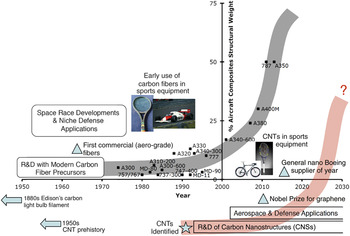
The future of carbon nanomaterials in advanced applications is compared in Figure 3 to the development of CFRP composites and their penetration into different markets, primarily commercial aerospace, where an S-curve is observed. Reference Rogers69 The parallels of micron-scale carbon fiber and nanometer-scale CNTs are many, both in terms of materials science and their development and adoption. Carbon fibers were considered in the early days for aerospace and military applications, many involving undisclosed or recently disclosed projects, running in parallel to lower “grade” materials and applications such as sports equipment. CNT-comprised materials and, more broadly, carbon nanostructures, are following a similar but perhaps accelerated trajectory. In this context, the rate of progress of adoption of carbon nanostructures is relatively quick providing a bright outlook for increased development. It is striking that the development of hierarchical composites has largely been experimentally driven thus far.
Carbon fiber and carbon nanostructure (especially carbon nanotubes, CNTs) development from an aerospace perspective, showing S-curves for their use in commercial transport. The growth in the use of fiber-reinforced polymer composites is indicated by their percentage of the total structural weight of commercial aircraft, while a notional curve for nanostructures is presented based on a similarly rapid, early adoption for niche aerospace applications. Reference Harris, Starnes and Shuart1

Modeling studies of composites with reinforcement on two length scales are scarce. The significant difference in diameters of microfibers and CNTs (close to 1000 times) leads to numerical difficulties when these reinforcements need to be modeled simultaneously, but such models are now being developed. Reference Romanov, Lomov, Verpoest and Gorbatikh70–Reference Mishnaevsky and Dai73 They provide opportunities to investigate a large number of parameters and to simulate scenarios that are not yet possible to realize experimentally. For example, one of the models suggests that spatially resolved CNT networks are effective for the mitigation of stress concentrations at the microscale. Reference Romanov, Lomov, Verpoest and Gorbatikh70 These findings are in line with principles that nature uses to design high-performance biological composites. Reference Gorbatikh, Lomov and Verpoest74 Exploiting CNT networks that are interconnected with fibers promises to yield fundamental changes in the failure process, thereby affecting properties.
The field of hierarchical composites is a young one and is taking its first steps, with many interesting developments to come. Until now, the community has focused on hierarchies utilizing only two scales of carbon materials (microscopic fibers and nanoreinforcements). Nature does it in much more intricate ways with more material combinations and more hierarchy levels. Further research is needed to understand the role of gradient nanostructures and how they are optimized for multiple properties. With the emergence of nanomaterials such as the two-dimensional graphene, it is now possible to investigate synergistic effects between different types of nanoscale reinforcements on the performance of structural composites.
Acknowledgments
The authors would like to acknowledge the support of the Skolkovo Institute of Science and Technology in the Russian Federation through the No. 335-MRA Project linked to the Center for Design, Manufacturing, and Materials. They would also like to thank G. Harjkova, R. Parnas, I. Straumit, and N.Q. Nguyen for the images in Figure 1.