Introduction
In 1962 N.G. Basov and O.N. Krokhin reported the idea of spherical compression of matter under powerful laser illumination (Basov and Krokhin, Reference Basov and Krokhin1964). Further developments resulted in the concept of inertial confinement fusion (ICF) (Duderstadt and Moses, Reference Duderstadt and Moses1982). The goal of ICF is to swiftly heat and compress small capsules of hydrogen fuel with a powerful driver. Ideally – spherically symmetric. The largest operational ICF experiment is the National Ignition Facility (NIF) (https://lasers.llnl.gov /). NIF era opened a door to the highest standards of laser experiments, hopefully demonstrated the scientific breakeven and, at the same time, put serious questions for the additional studies of targets and their behavior when formed, characterized, and transformed into plasma.
A key element of an ICF facility is a target with cryogenic hydrogen fuel. The ignition requires that the inner-surface roughness of solid hydrogen is less than 1 µm rms in all modes (Sangster et al., Reference Sangster2007). This means that the mechanical vibration should be less than solid H2 roughness during the target characterization. Furthermore, the ice surface quality depends on the temperature stability and cooling rate. For high-quality layering experiments, the desired temperature stability is ±1 mK over 10 minutes (General Atomics Report). The slow rate ~1 mK/minute allowed the strain that was induced during cooling to be relieved before further strain was incurred upon additional cooling (Harding et al., Reference Harding, Elasky, Verbridge, Weaver and Edgell2004).
According to the NIF concept-proof cryostat the surface that the target is mounted to must be maintained at 7.0 K providing 200 mW of cooling (Haid, Reference Haid2006).
The cooling techniques
Liquid He cryostat
The advantages of liquid helium cryostat are stable constant base temperature and operation without mechanical vibrations. The main disadvantage might seem logistical problems inside the laser facility.
The typical helium consumption for the on-table continuous flow helium cryostat is relatively low (less than 0.45 liter/hour (www.oxford-instruments.com/products/cryogenic-environments/optical-cryostats-for-spectroscopy/liquid-helium-cryostats-(4k)/helium-optical-2-2k-500k-cryostat-with-narrow-tail). But the distance between the remote MJ class cryostat and the liquid helium vessel exceeds 10 m. The typical heat leakage in the standard helium transfer line is 0.7 W/m (https://www.cryomech.com/products/cryorefrigerators/pulse-tube/pt415/), that means liquid helium consumption of about 10 liters/hour. The special transfer line where return cold gas cools the thermal shield is more effective, but the long transfer line is the real issue.
Bath cryostats require additional liquid nitrogen cooled thermal shield or multi-layer thermal insulation (MLI). The liquid nitrogen vessel increases the size of the cryostat and the number of gas connections. The additional shield is required to prevent tritium from contaminating the MLI. If this were to happen, it would be difficult to decontaminate the MLI due to its large surface area (Gibson et al., Reference Gibson, Charmin, Del Bene, Hoffmann, Besenbruch and Anteby1998).
Cryogen-free cryostats with mechanical cryocoolers
Cryogen-free systems have developed rapidly and become popular in research laboratories due to simple and low-cost operation (Naumov et al., Reference Naumov, Lyubutin, Frolov and Demikhov2010). Gifford–McMahon (GM) and pulse tube (PT) cryogenic refrigerators (cryocoolers) are applied to cool down samples and superconducting magnets without liquid helium (Demikhov et al., Reference Demikhov, Kostrov, Lysenko, Piskunov and Troitskiy2010, Reference Demikhov, Kostrov, Lysenko, Demikhov and Piskunov2012, Reference Demikhov, Demikhov, Kostrov, Lysenko and Piskunov2014; Rybakov et al., Reference Rybakov, Bagdinov, Demikhov, Kostrov, Lysenko, Piskunov and Tysyachnykh2016; Bagdinov et al., Reference Bagdinov, Demikhov, Kostrov, Lysenko, Piskunov, Rybakov and Tysyachnykh2018).
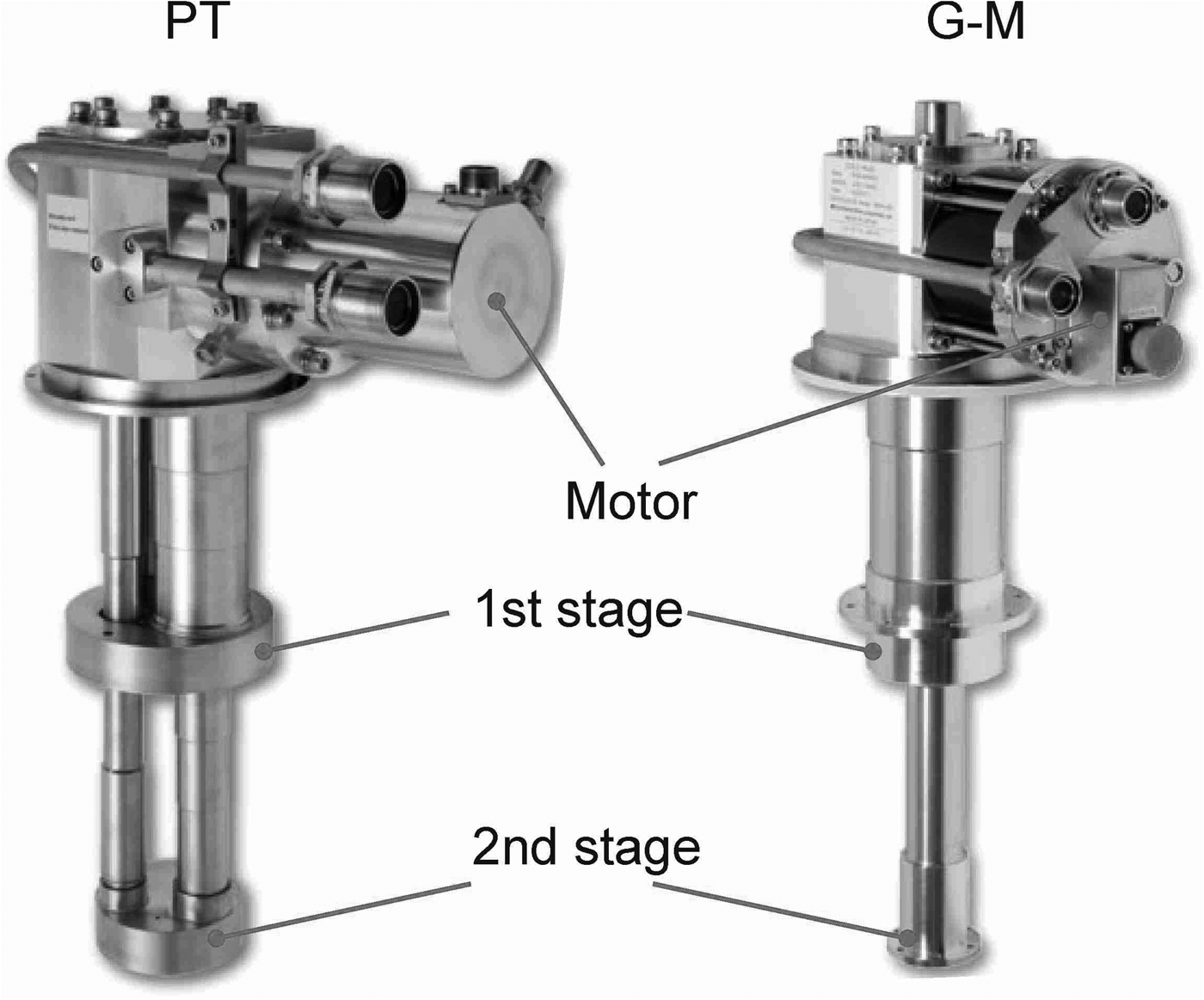
A 4 K cryocooler has two stages. The first stage is intended to cool the thermal radiation shield and intercept the heat coming to the second stage from room temperature surfaces by mechanical supports and electrical wires. The object that is required to be cooled should be connected to the second stage. The photos of PT and GM cryocoolers are shown in Figure 1.
The SHI RP082B2 Pulse tube and SHI RDK408 Gifford–McMahon cryocoolers.

The achievements in rear earth regenerative materials allowed to improve significantly the performance of GM and PT cryocoolers (Ohtani et al., Reference Ohtani, Hatakeyama, Nakagome, Usami, Okamura and Kabashima1999; Xu et al., Reference Xu, de Waele and Ju1999). Present commercially available GM and PT cryogenic refrigerators have 1–1.5 W of cooling power at the second stage and about 40–45 W at 45 K (RDK-408 and RP-082 by SHI (http://www.shicryogenics.com/products/) and PT415 by Cryomech (https://www.cryofab.com/products/cryogenic-transfer-lines/liquid-helium-transfer-line-CFHT).
The GM cooler can be operated in any angular orientation. The PT cooler must be operated in the vertical orientation with the cold end down. A change in the operating orientation of 15° can degrade the cooler performance by 15% or 20%. Commercial PT coolers available today do not produce cooling when horizontal (Green and Witte, Reference Green and Witte2008). In addition, the operation time of the PT coldhead is twice longer than that of the GM coldhead. This makes the operation cost lower.
Usually the GM coldhead is cheaper than the PT one, however, the moving displacer in the GM coldhead produces additional vibrations and the magnetic noise. The vibration amplitude of the second stage of the PT coldhead is 14 µm (peak to peak) that is two times smaller than for the GM cryocooler (Tomaru et al., Reference Tomaru, Suzukia, Haruyamaa, Shintomia, Yamamotoa, Koyamab and Lib2004).
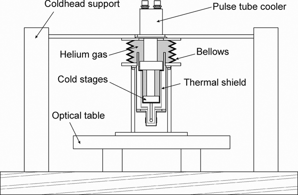
The vibration can be reduced to sub-micron values with vibration isolation techniques. Figure 2 shows a schematic view of the optical cryostat developed in our laboratory. The cryocooler and cryostat are fixed on independent rigid supports and connected with soft rubber bellows. The refrigerator's cold stages do not have mechanical contact with the cryostat and are thermally connected to the thermal shield and the sample holder by means of the helium gas.
The schematic view of the optical cryostat with sub-micron vibrations.

This scheme allows to achieve sub-micron vibration on the sample. For example, the vibration on the sample in the laser interferometer cryostat (Japan) for the detection of gravity waves with copper braided wires used as thermal links reduced to the amplitude of 0.1 µm (Ikushima et al., Reference Ikushima, Li, Tomaru, Sato, Suzuki, Haruyama, Shintomi and Yamamoto2008). Unfortunately, well-developed vibration reducing methods for the laboratory cryostats cannot be used in the target chamber.
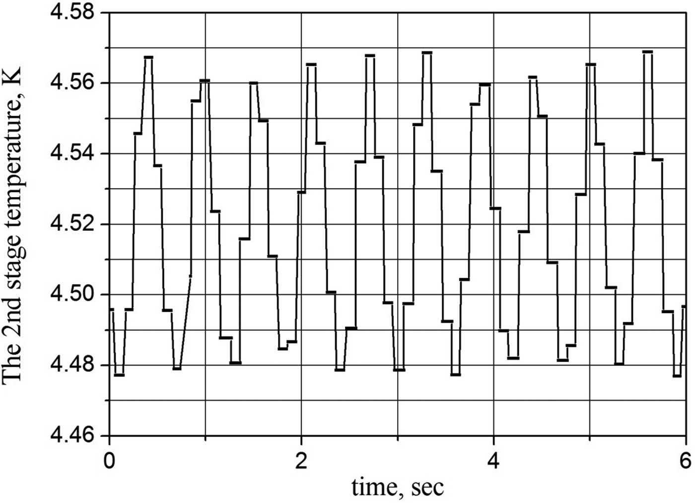
It is necessary to note that the second stage temperature fluctuates with peak to peak value of up to 90 mK. Figure 3 shows the measured temperature oscillations of the second stage of SRP082B2 PT cooler.
Temperature oscillations of the second stage of SRP 082 B2.

The solution of the equation for one-dimensional non-stationary heat conduction through the homogeneous solid gives for the peak-to-peak oscillation value as: (Allweins et al., Reference Allweins, Qiu and Thummes2008)
 $$\Delta T(x) = \Delta T(0){\rm} exp( - x \cdot ({\rm \pi} f/{\rm \alpha} )1/2)$$
where x is the distance from the second stage, ΔT(0) is the oscillation amplitude on the second stage surface, α = λ/(ρ c p) is the thermal diffusivity, ρ is the density, c p is the volumetric specific heat, λ is the thermal conductivity of solid and f = 1.0 Hz is the frequency of temperature oscillation According to Eq. (1) the thermal diffusivity should be decreased to reduce the amplitude of temperature fluctuations. The successful damping of the temperature oscillations by means of the rare earth plate (Allweins et al., Reference Allweins, Qiu and Thummes2008), stainless steel plate (Masuyama and Fujita, Reference Masuyama and Fujita2008), and the helium pot (Okidono et al., Reference Okidono, Oota, Kurihara, Sumida, Nishioka, Kato, Matsumura and Sasaki2012) are reported. The He-pot allows to reduce the temperature oscillations of the cryocooler without compromising cooling power.
Experimental setup
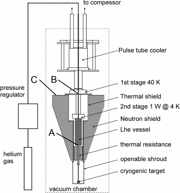
The target cryostat is intended to operate in a vertical position so that the PT cryogenic refrigerator has been selected as the cooling source. The cooling capacity of the two-stage PT cryocooler is 1W at 4.2 K on the second stage. The designed operation mode is 3 minutes off and 15 minutes on. The deactivation of PT cryocooler allows to achieve the target position stability of 1 micrometer or less during the X-ray characterization. Upon shutting off the cryocooler, the cryogenic target temperature remains constant due to liquid helium vessel acting as a heat reservoir. The schematic view of the experimental setup is presented in Figure 4.
Experimental cryogenic setup for MJ class laser targets to be kept at 5–25 K and sub-micron vibrations. (A) liquid-He vessel bottom, (B) first stage of the cooler, (C) neutron-shield top at its half radius.

The helium gas is supplied by a standard 40 liters (150 bar) helium gas cylinder equipped with a pressure-reducing valve. The electronic mass flow meter is used to precisely measure the helium gas flow into the liquid helium vessel which indicates a liquefaction rate.
Two electronic pressure regulators (upstream and downstream) are involved to control helium gas flow and maintain constant vapor pressure during the operation and deactivation of the cryocooler. The helium supply system is not closed. The helium evaporated during stopping the refrigerator flows outside the system.
The incoming helium gas needs to be pre-cooled since the specific enthalpy change of the gas between the room temperature and 4.2 K is 1540 J/g, while the latent heat of condensation at normal pressure is only 20.9 J/g. The gas pre-cools by means of the heat exchanger connected to the first stage and liquefies on the heat exchanger built-in the helium vessel. Various designs of cooler-based small-scale helium liquefiers could be found elsewhere (Thummes et al., Reference Thummes, Wang and Heiden1998; Schmidt-Wellenburg and Zimmer, Reference Schmidt-Wellenburg and Zimmer2006, Wang, Reference Wang2009).
The liquid helium vessel with the second stage of the PT cooler, thermal resistance and cryogenic target is placed inside the thermal radiation shield. The radiation shield is connected to the first of the PT refrigerator. The lower part of the thermal shield is openable by means of the conventional electrical mechanical actuator (not shown in Fig. 4).
The thermal resistance allows to limit heat transfer from the target to helium vessel to the designed value. An additional function of the thermal resistance is to reduce temperature oscillations coming from the second stage of the PT cooler.
The neutron shield is manufactured of boron doped polyethylene – polymer with high hydrogen concentration and boron.
The use of liquid helium instead the pressurized helium gas allows to reduce the vessel volume due to both a greater available cooling per volume and a substantial reduction in the control heat that is no longer required for offsetting the rising vessel temperature upon shutting the cooler off.
Test results
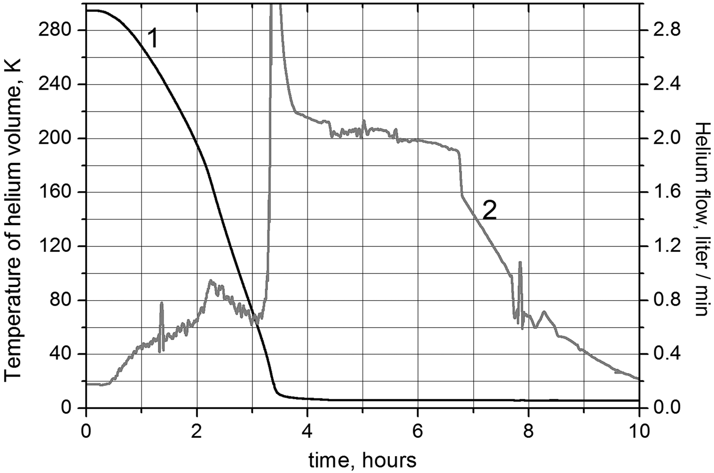
Figure 5 illustrates the cool-down, which was completed in within 7 hours. The cooling process begins as soon as the vacuum in the cryostat chamber is down to 10−3 mbar. The helium feeding line and vessel were evacuated and filled with helium gas. The pressure of the gas is maintained constant by the pressure regulation system. The liquefaction starts in 3.5 hours after the cooler is turned on. The corresponding flow rate is shown on the right scale of the graph.
Cooldown process on the second stage (less than 4 hours) and helium liquefaction – black curve 1 (left scale). Helium flow with maximum at temperature less than 70 K – grey curve 2 (right scale).

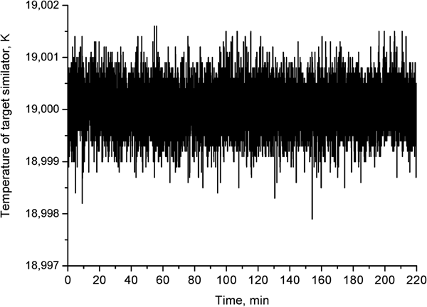
Figure 6 shows the temperature oscillation of the target simulator. The oscillation amplitude of the temperature is less than 2 mK when the target temperature is 19 K. This indicates that temperature oscillations (90 mK peak to peak) are reduced effectively on the liquid helium vessel and by temperature resistance.
Temporal temperature stability within 2 mK with target kept at 19 K.

The temperature of a target simulator was actively controlled by a proportional–integral–derivative temperature controller (PID-controller) that monitors the sensor and drives the heater.
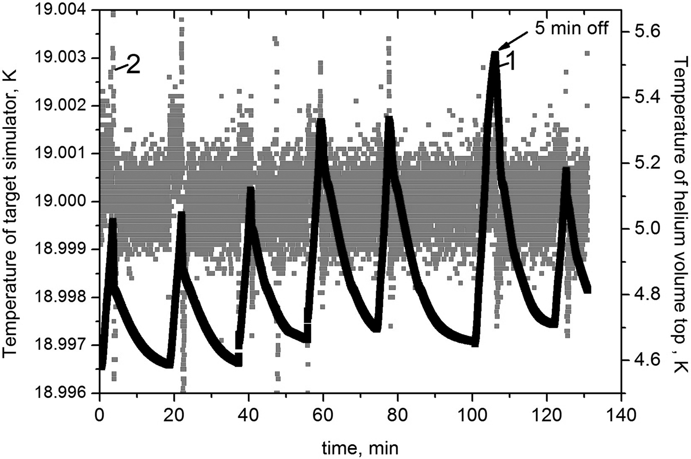
Figure 7 shows the temperature stability during on/off cycles. The first three cycles were 3 minutes off and 15 minutes on. The cooler stopped on 3.5 minutes during cycles 4 and 5. The refrigerator operated for 22 minutes after the fifth cycle and was turned on for 5 minutes during the sixth cycle. The temperature of the target simulator remained constant during the on/off cycles. It is assumed that temperature instabilities with an amplitude of 4 mK are concerned with instabilities in the power line caused by shutting on and off the powerful helium compressor.
Temperature stability during on/off cycles. (1) Temperature of target simulator(left scale), (2) temperature of helium volume top (right scale).

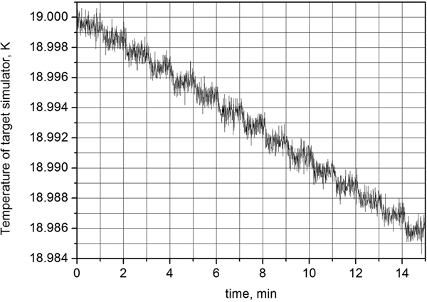
The slow cooling rate is crucial for high-quality target formation. Figure 8 shows the experimental data on the cooling with 1 mK/min rate.
The slow cooling process with the rate of 1 mK/minute.

The experimental setup allows to realize the cooling rate in the range of 1 mK – 1.5 K/minute.
Monte-Carlo simulation of the neutron shield
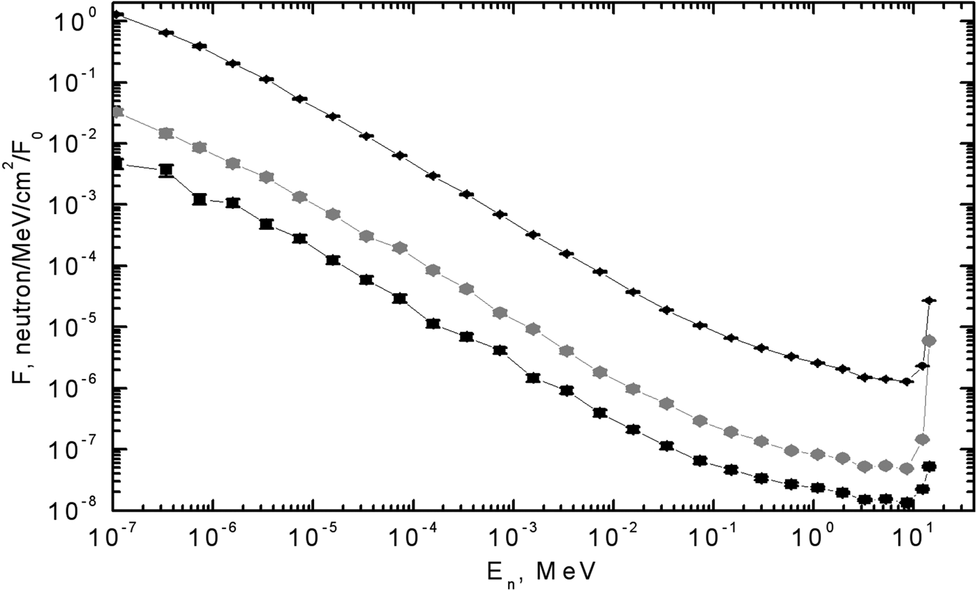
Using Monte-Carlo simulation the neutron shield effect for neutron flux was calculated. SHIELD program was implemented (http://www.inr.ru/shield/). This program already proved successful for the neutron collimators (Konobeevsky et al., Reference Konobeevsky, Latysheva, Sobolevsky and Ilić2011) and radioactive protection (Konobeevsky et al., Reference Konobeevsky, Latysheva and Sobolevsky2010) simulations. For present simulation Track Length Estimation in small surrendering detection-point volume was used. The isotropic flux of neutrons with energy E n(0) = 14.1 MeV are generated in the target. We considered only neutrons directed in the necessary solid cone. The amount of these neutrons is 10E + 7. The total amount of neutrons yielded from target per one laser pulse (in 4π) is F 0 = 450 034 368. Figure 9 shows energy dependence of the neutron flux at liquid-He vessel bottom (point A at Fig. 4), at the first stage of the cooler (point B at Fig. 4) and on neutron-shield top at its half radius (point C at Fig. 4). In these curves, the flux is normalized by F 0.
The energy dependence of the neutron flux at three points of the cryostat: At point A (upper), at point B (middle), and on point C (lower) normalized by total neutron flux.

Summary
The concept-proof prototype cryostat for MJ class laser target is developed and tested. The mechanical cryocooler is the cooling source for helium gas liquefaction. The liquid helium vessel serves for temperature stabilization while the cooler is off. The basic requirements for cryogenic targets are achieved. Further optimization is possible.
The effect of the neutron shield for flux of neutrons with En(0) = 14.1 MeV is 2 orders of magnitude. But the effect of the slowed down neutrons is important too. The total flux in presence of the shield drops from 3 (for point A) to 20 times (for point C). The obtained data should be taken into account when assessing the lifetime of cooler and other devices.
The construction is capable of modifications such as direct-indirect and other complex target design implementations in beam-target interaction experiments.