
1. Introduction
Atomic force microscopy (AFM) has emerged as a vital tool for characterising the mechanical and surface properties of small-scale materials and structures (Binnig, Quate & Gerber Reference Binnig, Quate and Gerber1986). In a typical experiment, a probe attached to an AFM cantilever is brought into contact with a test object, while the displacement and deflection of the cantilever are meticulously recorded. By utilising the pre-calibrated stiffness of the cantilever, the deflection measurements can be translated into applied force data. Interestingly, the force–displacement behaviour during contact is not often smooth (Baró & Reifenberger Reference Baró and Reifenberger2012). In particular, long-range intermolecular forces, such as van der Waals (vdW) and double-layer forces, increase more sharply than the cantilever’s elastic restoring force (French et al. Reference French2010). When the probe–substrate gap narrows to a critical threshold, the probe can rapidly snap toward the test object – a phenomenon known as jump-to-contact (Israelachvili Reference Israelachvili2011). In fact, this effect has been pivotal in quantifying intermolecular force strengths between rigid objects (Tomlinson Reference Tomlinson1928; Tabor & Winterton Reference Tabor and Winterton1969). A notable example is the measurement of non-retarded vdW forces, determined by identifying the critical gap at which the jump-to-contact occurs (Tabor & Winterton Reference Tabor and Winterton1969; Israelachvili & Tabor Reference Israelachvili and Tabor1972).
When the substrate is deformable, the jump-to-contact can, in principle, still be employed to measure vdW interactions between the probe and the substrate (Israelachvili Reference Israelachvili2011). However, interpreting the jump-to-contact point becomes much more complex due to the interplay between nonlinear vdW interaction and substrate deformation, as demonstrated in recent experiments on liquid surfaces (Chireux et al. Reference Chireux, Protat, Risso, Ondarçuhu and Tordjeman2018). This complexity is further compounded when the experimental objective involves probing the mechanical response of an elastic surface, requiring analysis of the force–displacement relationship after contact is established (Ciavarella et al. Reference Ciavarella, Joe, Papangelo and Barber2019). A common strategy to simplify such analyses is to apply a sufficiently large force, effectively bypassing the intricacies of the jump-to-contact phenomenon (Johnson & Greenwood Reference Johnson and Greenwood1997). In this regime, classical models such as Hertz theory or the Johnson–Kendall–Roberts theory can be utilised directly (Krieg et al. Reference Krieg, Fläschner, Alsteens, Gaub, Roos, Wuite, Gaub, Gerber, Dufrêne and Müller2019). To either leverage or avoid the effects of the jump-to-contact, developing a quantitative understanding of this phenomenon on deformable substrates is crucial.
So far, the jump-to-contact of spherical AFM probes has been examined in the context of both linearly elastic substrates (Greenwood Reference Greenwood1997; Feng Reference Feng2000; Wu Reference Wu2010; Ciavarella, Greenwood & Barber Reference Ciavarella, Greenwood and Barber2017; Yu & Dai Reference Yu and Dai2024) and liquid surfaces (Liu et al. Reference Liu, Bai, Xia and Ke2005; Ledesma-Alonso, Legendre & Tordjeman Reference Ledesma-Alonso, Legendre and Tordjeman2012; Quinn, Feng & Stone Reference Quinn, Feng and Stone2013; Mortagne et al. Reference Mortagne, Chireux, Ledesma-Alonso, Ogier, Risso, Ondarçuhu, Legendre and Tordjeman2017; Chireux et al. Reference Chireux, Protat, Risso, Ondarçuhu and Tordjeman2018). It has been elucidated that substrate deformation reduces the effective gap beneath the probe, leading to a premature jump compared to rigid substrates (Yu & Dai Reference Yu and Dai2024). For rigid cantilevers, the jump can also occur due to the deformation of the substrate itself, as seen with liquid surfaces (Ledesma-Alonso et al. Reference Ledesma-Alonso, Legendre and Tordjeman2012; Quinn et al. Reference Quinn, Feng and Stone2013). Despite this progress, the jump-to-contact phenomena that have been observed in AFM experiments involving a wide range of soft materials, including cells, gels, two-dimensional crystals and biological tissues (Baró & Reifenberger Reference Baró and Reifenberger2012; Dai, Liu & Zhang Reference Dai, Liu and Zhang2019; Krieg et al. Reference Krieg, Fläschner, Alsteens, Gaub, Roos, Wuite, Gaub, Gerber, Dufrêne and Müller2019; Viljoen et al. Reference Viljoen, Mathelié-Guinlet, Ray, Strohmeyer, Oh, Hinterdorfer, Müller, Alsteens and Dufrêne2021; Zheng & Dai Reference Zheng and Dai2025), have introduced new physical factors, preventing the direct application of prior results obtained for elastic substrates or liquid surfaces.
On the one hand, due to the compliance of soft materials such as gels, the solid surface tension can be comparable to or even dominate elastic forces in controlling substrate deformation in response to the vdW attraction from the probe (Krichen, Liu & Sharma Reference Krichen, Liu and Sharma2019; Zhu et al. Reference Zhu, Ni, Huang, Yu, Yao and Zheng2025). For example, in line with typical elasto-capillary problems (e.g. as reviewed in Style et al. Reference Style, Jagota, Hui and Dufresne2017; Bico, Reyssat & Roman Reference Bico, Reyssat and Roman2018; Andreotti & Snoeijer Reference Andreotti and Snoeijer2020), one may define an elasto-capillary parameter
 $\Gamma = \gamma /(G\ell)$
to characterise the effect of solid surface tension
 $\gamma$
, where
 $G$
is the shear modulus of the substrate, and
 $\ell$
is a characteristic length. Also, one may expect that for
 $\Gamma \ll 1$
, the results of the jump-to-contact problem will converge to the case without surface tension, while for
 $\Gamma \gg 1$
, the behaviour will resemble that of a liquid surface. However, a detailed understanding of how the surface tension affects the jump-to-contact remains absent. Moreover, we will demonstrate that the expectation of the convergence to the two limiting cases above is not entirely accurate because of the complex elasto-capillary interaction at the far field (
 $r/\ell \sim \Gamma$
).
On the other hand, soft biological materials are often tested in liquid environments, where the probe’s approaching dynamics has been found to significantly influence the measured results (Viljoen et al. Reference Viljoen, Mathelié-Guinlet, Ray, Strohmeyer, Oh, Hinterdorfer, Müller, Alsteens and Dufrêne2021; Chen et al. Reference Chen, Li, Liao, Li, Li, Yin and Guo2022). A particular example can be given by the absence of a clear ‘contact point’ and the observation of speed-dependent Young’s modulus in AFM-based mechanobiology (Krichen et al. Reference Krichen, Liu and Sharma2019). This issue arises when the contact force–displacement data are collected in a liquid environment AFM, but interpreted using the simple Hertz theory, which assumes a well-defined zero-force and zero-displacement reference contact point (Krieg et al. Reference Krieg, Fläschner, Alsteens, Gaub, Roos, Wuite, Gaub, Gerber, Dufrêne and Müller2019). Another example involves the subtle jump-to-contact behaviour during slow approaches: the force felt by the cantilever may initially be repulsive, transitioning to an attractive regime before the jump point (as observed in figure S1 in Wegmann et al. Reference Wegmann, Medalsy, Mandelkow and Müller2013). These observations are likely signatures of viscous repulsion of the squeezed liquid film (Rallabandi Reference Rallabandi2024), reminiscent of elastohydrodynamic attraction seen when a liquid gap is opened (Wang, Feng & Frechette Reference Wang, Feng and Frechette2020; Bertin, Oratis & Snoeijer Reference Bertin, Oratis and Snoeijer2025). To quantify how the approaching dynamics affects jump-to-contact behaviour – or when such effects can be safely neglected – an understanding of the interplay of hydrodynamic and vdW interactions between the AFM probe and the deformable substrate is essential but remains lacking.
In this work, we consider the statics and dynamics of jump-to-contact behaviour on elastic substrates incorporating the effects of solid surface tension. Special emphasis is placed on the substrate deformation during the jump-to-contact process, as well as on the critical force and cantilever position at the onset of the jump. We demonstrate that even under very high solid surface tension, elasticity can significantly influence and smooth the substrate deformation in the far field. We also provide a criterion regarding the approaching velocity for these static results to be useful. The remainder of the paper is organised as follows. In § 2, we formulate the static problem, derive the governing equations for jump-to-contact, and identify the key dimensionless parameters. In § 3, we focus on substrates with small deformability, and present asymptotic solutions in the limits of small and large solid surface tensions. These solutions quantify how the deformation of a substrate with surface tension causes the jump to occur prematurely. In § 4, we use lubrication theory to examine the effect of probe approach dynamics, showing that viscous resistance can delay this premature jump-to-contact. Finally, in § 5, we summarise our findings and discuss their potential implications for AFM-based measurements on soft materials.
2. The static model
2.1. Problem description
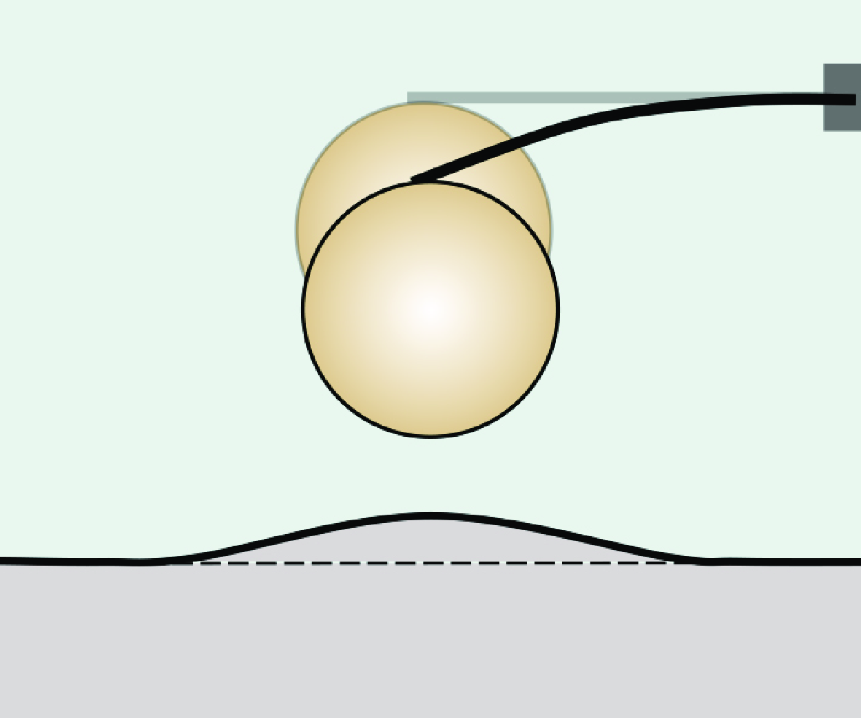
We first discuss the static problem. As shown in figure 1, one end of the cantilever is fixed to a piezo-actuated holder positioned at height
 $d$
above the undeformed surface of the test substrate. The opposite end of the cantilever is equipped with a spherical probe or tip of radius
 $R_s$
. The height of the holder can then be expressed as the sum of the cantilever deflection
 $\delta$
, the height of the probe
 $s$
, and a reference distance
 $d_{{ref}}$
:
 \begin{equation} d=\delta +s+d_{{ref}}. \end{equation}
Since
 $d_{{ref}}$
is a fixed, absolute distance that requires specific calibrations in experiments (Krieg et al. Reference Krieg, Fläschner, Alsteens, Gaub, Roos, Wuite, Gaub, Gerber, Dufrêne and Müller2019), we will disregard it and focus on the relative cantilever position (i.e.
 $d-d_{{ref}}$
) in subsequent discussions.
Jump-to-contact of an AFM probe with an elastic substrate influenced by surface tension. The probe, with radius
 $R_s$
, is mounted on a cantilever of spring constant
 $k$
. The cantilever is controlled by a holder positioned at height
 $d$
above the undeformed surface.

The cantilever deflection is caused by the attractive force
 $F$
between the probe and the substrate. Considering the cantilever stiffness
 $k$
, the deflection
 $\delta$
is given by
 \begin{equation} \delta = \frac {F}{k}. \end{equation}
The interaction force
 $F$
originates from intermolecular forces between the probe and the substrate across the intervening medium (typically air or liquid in AFM experiments):
 \begin{equation} F = 2\unicode{x03C0} \int _0^\infty p(r)r \,\mathrm{d} r. \end{equation}
In this work, we focus on non-retarded vdW forces and account for the substrate deformation
 $w(r)$
(see figure 1). The interaction force per unit area at location
 $r$
can then be described by
 \begin{equation} p(r) = \frac {4A R_s^3}{3\unicode{x03C0} \left [\left (s + R_s - w\right)^2 + r^2 - R_s^2\right]^3}, \end{equation}
according to Hamaker theory (Israelachvili Reference Israelachvili2011), where
 $A$
is the Hamaker constant. Finally, determining the substrate deformation requires solving the boundary value problem for an elastic half-space subjected to normal traction arising from vdW forces and surface tension, which is expressed as
 \begin{equation} \sigma _{zz}(r, z=0) = p(r) + \gamma\, \boldsymbol{\nabla} \cdot \boldsymbol{n}, \end{equation}
where
 $\boldsymbol{n}$
represents the normal vector to the deformed surface
 $z = w(r)$
of the elastic half-space, and
 $\gamma$
is the constant surface tension of the substrate surface. The full expression for the second term on the right-hand side of (2.5) is given by
 \begin{equation} \gamma \boldsymbol{\nabla} \cdot \boldsymbol{n} = \frac {\gamma }{r} \frac {{\mathrm{d}}}{\mathrm{d} r} \left ( \frac {r w^{\prime}}{\sqrt {1 + {w^{\prime}}^2}} \right), \end{equation}
where
 $w^{\prime}$
denotes
 $\mathrm{d} w / \mathrm{d} r$
.
The axisymmetric nature of the problem specified above allows it to be solved more conveniently by transforming it into the Hankel domain (Box et al. Reference Box, Jacquemot, Adda-Bedia and Vella2020; Essink et al. Reference Essink, Pandey, Karpitschka, Venner and Snoeijer2021). The
 $n$
th-order Hankel transform is defined as (Sneddon Reference Sneddon1995)
 \begin{equation} \tilde{f}(\xi) = \mathcal{H}_n[f(r)] = \int _0^\infty f(r) J_n(\xi r) r \,\mathrm{d} r, \end{equation}
with the inverse transform given by
 \begin{equation} f(r) = \mathcal{H}_n^{-1}[\tilde{f}(\xi)] = \int _0^\infty \tilde{f}(\xi)\, J_n(\xi r) \xi \,\mathrm{d} \xi. \end{equation}
In the Hankel domain, the linear elastic response of a semi-infinite elastic substrate is expressed as
 \begin{equation} \tilde{w}(\xi) = \frac {1 - \nu }{G \xi }\, \tilde{\sigma }_{zz}(\xi, z = 0), \end{equation}
where both
 $\tilde{w}(\xi)$
and
 $\tilde{\sigma }_{zz}$
correspond to the zeroth-order Hankel transform, and
 $\nu$
and
 $G$
are the Poisson’s ratio and shear modulus of the substrate, respectively (Hannah Reference Hannah1951; Sneddon Reference Sneddon1995). Note that this transformation method is essentially identical to the Green’s function method, but it is limited to axisymmetric geometries (Rallabandi Reference Rallabandi2024).
2.2. Non-dimensionalisation
Tabor & Winterton (Reference Tabor and Winterton1969) utilised rigid substrates and relatively large probes in their experiments to measure vdW forces. This set-up allows them to derive the analytical relations
 \begin{equation} F = \frac {A R_s}{6s^2} \quad \text{and} \quad d = s + \frac {A R_s}{6ks^2} \end{equation}
by substituting (2.4) into (2.3), assuming
 $w = 0$
and
 $s \ll R_s$
. In this rigid limit, the critical gap, force, and holder position at the onset of the jump can be directly obtained as
 \begin{equation} s_c = \frac {1}{3^{1/3}}\left (\frac {A R_s}{k}\right)^{1/3}, \quad F_c = \frac {1}{2 \times 3^{1/3}}(A k^2 R_s)^{1/3} \quad \text{and}\quad d_c = \frac {3^{1/3}}{2}\left (\frac {A R_s}{k}\right)^{1/3}. \end{equation}
While this work considers a soft, deformable substrate, we continue to use the characteristic lengths suggested by the rigid limit. This is because the measurements on soft substrates or thin flexible materials typically use very compliant cantilevers for improved force sensitivity (Wegmann et al. Reference Wegmann, Medalsy, Mandelkow and Müller2013; Krieg et al. Reference Krieg, Fläschner, Alsteens, Gaub, Roos, Wuite, Gaub, Gerber, Dufrêne and Müller2019; Dai et al. Reference Dai, Lu, Liechti and Huang2020). In this case, the induced deformation of the substrate remains small compared to the deflection of the cantilever (so it is the probe that jumps). We adopt the following vertical characteristic length, as suggested by (2.11),
 \begin{equation} s_*:= \left ( \frac {A R_s}{k} \right)^{1/3}, \end{equation}
which subsequently gives rise to the horizontal characteristic length by incorporating the probe geometry,
 \begin{equation} \ell _*:= (R_s s_*)^{1/2}. \end{equation}
Note that in typical experimental set-ups,
 $s_*$
can be tuned by varying the sphere radius and cantilever stiffness, with values spanning from a few nanometres to several microns, while
 $s_*$
is always much smaller than
 $\ell _*$
(Binnig et al. Reference Binnig, Quate and Gerber1986; Israelachvili & Tabor Reference Israelachvili and Tabor1972). Utilising (2.12) and (2.13), along with corresponding levels of vdW forces, we rescale the variables in real and Hankel spaces to introduce dimensionless variables:
 \begin{equation} \begin{aligned} & R=\frac {r}{\ell _*},\quad D=\frac {d}{s_*},\quad S=\frac {s}{s_*},\quad W=\frac {w}{s_*},\quad \mathcal{F}=\frac {Fs_*^2}{AR_s},\quad P=\frac {ps_*^3}{A},\\ & \Xi =\xi \ell _*,\quad \tilde{W}=\frac {\mathcal{H}_0[w]}{s_*\ell _*^2},\quad \tilde{P}=\frac {\mathcal{H}_0[p]s_*^2}{A\ell _*^2}. \end{aligned} \end{equation}
With (2.14), the problem specified in (2.1)–(2.9) can now be expressed as
 \begin{equation} D = \mathcal{F} + S, \end{equation}
where the attractive force between the probe and the deformed substrate is given by
 \begin{equation} \mathcal{F} = 2\unicode{x03C0} \int _0^\infty P(R) R \,\mathrm{d} R, \end{equation}
the dimensionless attractive vdW forces per unit area are given as
 \begin{equation} P(R) = \frac {4\alpha ^3}{3\unicode{x03C0} \left [\left (1 + \alpha S - \alpha W\right)^2 + \alpha R^2 - 1\right]^3}, \end{equation}
and the surface deformation satisfies the equilibrium equation in Hankel space,
 \begin{equation} \tilde{W}(\Xi)= \Gamma\, \mathcal{H}_1\left [\frac {R W_R}{\sqrt {1 + \alpha W_R^2}}\right] + (1 + \Gamma)\epsilon \frac {\tilde{P}(\Xi)}{\Xi }. \end{equation}
Here, we have integrated once to obtain the first term on the right-hand side of (2.18) (denoting nonlinear Laplace pressure caused by solid surface tension). In (2.18), we have defined the effective thickness of the gap beneath the probe as
 \begin{equation} \alpha:= \frac {s_*^2}{\ell _*^2}=\frac {s_*}{R_s}, \end{equation}
which is generally much less than unity. Therefore,
 $\alpha W_R^2$
in the Laplace pressure term in (2.18) will be dropped in numerics later in this study, such that
 $\mathcal{H}_1[RW_R]$
reduces to
 $-\Xi\, \tilde{W}(\Xi)$
. However, let us keep it in the analysis at this moment so that we will be able to illustrate that the small term associated with
 $\alpha$
is relatively more important in the vdW pressure than in the Laplace pressure.
In (2.18), we have also defined a parameter to characterise the effect of surface tension as
 \begin{equation} \Gamma:= \frac {(1-\nu)\gamma }{G\ell _*}, \end{equation}
which can be interpreted as an elasto-capillary number for elastic half-space systems (Style et al. Reference Style, Jagota, Hui and Dufresne2017; Bico et al. Reference Bico, Reyssat and Roman2018; Andreotti & Snoeijer Reference Andreotti and Snoeijer2020). Finally, we have introduced a parameter to characterise the effective compliance of the elastic substrate with solid surface tension in (2.18):
 \begin{equation} \epsilon:= \frac {A\ell _*^2}{G\ell _* s_*^4/(1-\nu)+\gamma s_*^4}=\frac {(1-\nu)AR_s^{1/2}}{(1+\Gamma)Gs_*^{7/2}}. \end{equation}
This effective compliance is defined by comparing the typical deformation of the substrate (
 $w_*$
) induced by the typical vdW force (
 $p_*$
) to the characteristic sphere–substrate gap
 $s_*$
, given in (2.12). The typical vdW force can be estimated by combining (2.12) and (2.4), resulting in
 $p_* \sim A / s_*^3$
in the regime where deformation is limited and the sphere is large. Estimating the typical substrate deformation requires some consideration, which we approach using an energy argument. Specifically, the external work done by vdW forces scales as
 $p_*\ell _*^2\, w_*$
. This work is stored as elastic energy, scaling as
 $G\varepsilon ^2 \, \ell _*^3$
, and as surface energy, scaling as
 $\gamma\, \Delta S$
, where the strain is
 $\varepsilon \sim w_*/\ell _*$
, and the increase in surface area is
 $\Delta S \sim w_*^2$
. By equating the stored energy to the external work, we find that
 $w_* \sim A\ell _*^2 / [(G\ell _* + \gamma)s_*^3]$
. This relationship yields (2.21) by comparing
 $w_*$
to
 $s_*$
(Poisson’s ratio is included for notational convenience).
Considering a typical soft gel with shear modulus
 $ G = 100$
kPa and Poisson’s ratio
 $ \nu = 0.5$
, along with a Hamaker constant
 $ A = 10^{-20}\,\mathrm{J}$
, solid surface tension
 $ \gamma = 10\,\mathrm{mN\, m^{-1}}$
, cantilever stiffness
 $ k = 0.1\,\mathrm{N\, m^{-1}}$
, and a spherical probe of radius
 $ R_s = 10\,{\unicode{x03BC} \mathrm{m}}$
, the characteristic scales are approximately
 $ s_* \approx 10\,\mathrm{nm}$
and
 $ \ell _* \approx 316\,\mathrm{nm}$
, yielding
 $ \alpha \approx 10^{-3}$
,
 $ \Gamma \approx 1.58$
and
 $ \epsilon \approx 0.61$
. Notably, ultrasoft cantilevers with stiffness
 $ k \sim 0.01\,\mathrm{N\, m^{-1}}$
are often employed to achieve high-resolution AFM imaging with enhanced force sensitivity (Wegmann et al. Reference Wegmann, Medalsy, Mandelkow and Müller2013), where
 $ \epsilon \sim 0.05$
. It is also worth noting that we have assumed linear elasticity for the substrate in the model. This assumption should be valid in typical colloidal AFM experiments since the strain scales as
 ${w_*}/{\ell _*}=\alpha \,\epsilon$
, which is small even when
 $\epsilon =\mathcal{O}(1)$
.
2.3. Numerical solution
The problem defined by (2.15)–(2.18) depends solely on three dimensionless physical parameters:
 $\alpha$
,
 $\Gamma$
and
 $\epsilon$
. Since
 $\alpha \ll 1$
in typical experiments, the focus lies in understanding the jump-to-contact behaviour of substrates with varying compliance
 $\epsilon$
under different surface effects
 $\Gamma$
. In all calculations, we let
 $\alpha = 10^{-2}$
(unless otherwise specified), as further reducing its value does not yield any noticeable changes in the numerical results. We solve this problem numerically using a uniform grid (refined near the origin) and the standard iterative method (Press et al. Reference Press, Teukolsky, Vetterling and Flannery2007). A grid with 5000 points over the real and Hankel domains
 $[10^{-3}, 10^{3}]$
can ensure convergence for the parameters considered in this work. It is worth mentioning that while experimental operations typically involve prescribing
 $D$
and measuring
 $S$
, it is computationally more convenient to prescribe the gap
 $S$
and solve for
 $D$
. This approach avoids complications arising from the existence of two solutions for a given
 $D$
(one stable and the other unstable, to be discussed with figure 2).
3. Premature jump-to-contact
3.1. Perturbation method
Although the problem is intrinsically nonlinear due to the vdW force, analytical progress can be made when
 $\epsilon$
is small. Note again that force measurements in AFM experiments can benefit from soft cantilevers (i.e. small values of
 $\epsilon$
). Specifically, based on the equilibrium equation (2.18), we conduct a perturbation analysis for the surface deformation and the vdW pressure, adopting the structure
 \begin{equation} W(R) = W_0(R) + \epsilon W_1(R) + O(\epsilon ^2), \quad P(R) = P_0(R) + \epsilon P_1(R) + O(\epsilon ^2). \end{equation}
Substituting (3.1) into (2.18) yields
 \begin{align} &\epsilon ^0 \left ( \tilde{W}_0 - \Gamma\, \mathcal{H}_1 \left [ \frac {R W_0^{\prime}}{\sqrt {1 + \alpha {W_0^{\prime}}^2}} \right] \right) \notag\\ &\qquad + \epsilon ^1 \left ( \tilde{W}_1 - \Gamma \mathcal{H}_1 \left [ \frac {R W_1^{\prime}}{\sqrt {1 + \alpha {W_0^{\prime}}^2}} \right] - (1 + \Gamma) \frac {\tilde{P}_0(\Xi)}{\Xi } \right) + \cdots = 0, \end{align}
which leads to the results
 \begin{equation} \tilde{W}_0 = 0, \quad \tilde{W}_1 = \frac {(1 + \Gamma) \tilde{P}_0}{\Xi (1 + \Gamma \Xi)}. \end{equation}
Clearly, the nonlinear term in the Laplace pressure does not influence the solution up to
 $O(\epsilon ^2)$
. Using this, the expression obtained by substituting (3.1) into (2.4) can be simplified as
 \begin{equation} \epsilon ^0 \left ( P_0 - \frac {4}{3 \unicode{x03C0} (R^2 + 2 S + \alpha S^2)^3} \right) + \epsilon ^1 \left ( P_1 - \frac {8 (1 + \alpha S) W_1}{\unicode{x03C0} (R^2 + 2 S + \alpha S^2)^4} \right) + \cdots = 0. \end{equation}
Combining (3.3) and (3.4), we obtain the zeroth-order solution
 \begin{equation} W_0 = 0, \quad P_0 = \frac {4}{3 \unicode{x03C0} (R^2 + 2 S + \alpha S^2)^3}, \end{equation}
and the first-order solution
 \begin{equation} W_1 = \mathcal{H}_0^{-1} \left [ \frac {\text{K}_2\left (\sqrt {S (2 + \alpha S)}\, \Xi \right)}{6 \unicode{x03C0} S (2 + \alpha S)} \frac {(1 + \Gamma) \Xi }{1 + \Gamma \Xi } \right], \quad P_1 = \frac {8 (1 + \alpha S)}{\unicode{x03C0} (R^2 + 2 S + \alpha S^2)^4} W_1, \end{equation}
where
 $ \text{K}_n$
denotes the modified Bessel function of the
 $ n$
th kind. While the first-order solution cannot be expressed analytically, we derive approximate analytical solutions within small and large surface tension limits.
Substrate deformation and the fold bifurcation. (a) Surface deformation of the elastic substrate for various gap values, as indicated by the colour bar. Markers represent numerical results, while solid curves correspond to the analytical solution given in (3.7). Only solid markers indicate stable and physically meaningful solutions, as the gaps for empty markers fall below the critical jump gap
 $S_c$
. (b) Gap as a function of the cantilever position for rigid (black curve, see (2.10)) and deformable (red curve, see (3.8)) substrates. Empty markers represent numerical results, while the two solid markers indicate the critical gap and the corresponding cantilever position where jump-to-contact occurs. All calculations are performed with
 $ \alpha = 0.01$
,
 $ \epsilon = 0.1$
and
 $ \gamma = 0.1$
.

3.2. Small surface tension
We first consider the case of small
 $\Gamma$
, allowing
 $(1+\Gamma)\Xi /(1+\Gamma \Xi)$
in the right-hand side of the first term in (3.6) to be approximated as
 $\Xi + \Gamma \Xi - \Gamma \Xi ^2$
. With this approximation, the inverse Hankel transform in (3.6) can be readily carried out, yielding
 \begin{align} W_1 &= \frac {1 + \Gamma }{6 \unicode{x03C0} S^{3/2} (2 + \alpha S)^{3/2} W_s^2} \notag\\ &\quad \times \left [ 2 (2W_s - R^2)\,\mathcal{E}\left (\frac {-R^2}{2 S + \alpha S^2}\right) - W_s\,\mathcal{K}\left (\frac {-R^2}{2 S + \alpha S^2}\right) \right] - \frac {4\Gamma }{3 \unicode{x03C0} W_s^3}, \end{align}
where
 $W_s(R) = 2S + \alpha S^2 + R^2$
, and
 $\mathcal{K}$
and
 $\mathcal{E}$
represent the elliptic integrals of the first and second kind, respectively. This solution, along with the first equation in (3.1), shows good agreement with the numerically calculated substrate deformation presented in figure 2(a), which is obtained using
 $ \alpha = 0.01$
,
 $ \epsilon = 0.1$
,
 $ \gamma = 0.1$
and various values of
 $S$
.
However, not all values of
 $S$
are physically meaningful, due to the jump-to-contact instability. This can be seen further by substituting (3.7) into the second equation of (3.6), and then combining (3.1) with (2.16), giving
 \begin{align} \mathcal{F}={}&\frac {2}{3 S^2 (2 + \alpha S)^2} \nonumber \\ &{}+ \left [ \frac {315 \unicode{x03C0} }{2048 \left (2S + \alpha S^2\right)^{11/2}} - \frac {32\,768 - 2835 \unicode{x03C0} ^2 \sqrt {S (2 + \alpha S)}}{18\,432\, \unicode{x03C0} S^6 (2 + \alpha S)^6} \Gamma \right](1 + \alpha S)\epsilon. \end{align}
Using this solution and the relation
 $D = S + \mathcal{F}$
from (2.15), we plot the gap between the probe and the undeformed substrate as a function of the AFM cantilever holder position in figure 2(b). As before, there is good agreement between the analytical solution (solid and dashed curves) and the numerical results (empty markers). In addition, a saddle-node (fold) bifurcation structure is observed (similar to pull-in instability in micro-electromechanical systems; Gomez, Moulton & Vella Reference Gomez, Moulton and Vella2017b
; Li, Yu & Dai Reference Li, Yu and Dai2024): for a typical given holder position, two gap solutions typically exist, with only the solution corresponding to the larger gap (i.e. the solid curves in figure 2
b) being stable. As the cantilever approaches the substrate, the stable solution eventually disappears at the point
 $(S_c, D_c, \mathcal{F}_c)$
, where it merges with the unstable solution (dashed curve) and the probe jumps into contact with the substrate.
Premature jump-to-contact on compliant substrates. (a) The gap under the probe and (b) the net attractive vdW force, as functions of the cantilever position for substrates with different compliances
 $\epsilon$
(encoded in the colour bar). Coloured empty markers represent numerical calculations, while the coloured curves are based on (2.15) and (3.8). The leftmost curve in black represents the rigid limit, as given by (2.10). Here,
 $\alpha =0.01$
and
 $\Gamma =0.1$
.

Compared to a rigid substrate, a compliant substrate undergoes surface deformation during the cantilever’s approach. Such deformation enhances the effective strength of vdW forces, causing jump-to-contact to occur prematurely, as shown in figure 2(b). This behaviour is further illustrated in figure 3, where the gap and net vdW attraction are plotted as functions of the cantilever position for substrates with various effective compliances
 $\epsilon$
. For the numerical calculations, we used
 $\Gamma = 0.1$
and
 $\alpha = 0.01$
, which show good agreement with the analytical solution given by (3.8) in combination with (2.15) for small
 $\epsilon$
. As the substrate compliance vanishes, the results converge to the rigid limit (black curves in figure 3) described by (2.10). For substrates with finite compliance, deformation induced by vdW forces leads to a premature jump-to-contact, corresponding to larger critical gaps and cantilever positions as well as smaller critical attractive forces. This clearly indicates that substrate deformation must be carefully accounted for when measuring the vdW interaction or surface adhesion of relatively soft materials using AFM (Krieg et al. Reference Krieg, Fläschner, Alsteens, Gaub, Roos, Wuite, Gaub, Gerber, Dufrêne and Müller2019). For instance, fitting experimental force curves with a rigid substrate model could lead to an overestimation of the interaction between tissues or living cells and probes coated with nanocarriers (Friedrichs, Helenius & Muller Reference Friedrichs, Helenius and Muller2010; Yu et al. Reference Yu, Zeng, Wang, Cui, Gao, Yin, Liu, Wei, Wei and Dai2025).
In figure 4, we present the critical force
 $\mathcal{F}_c$
and the critical cantilever position
 $D_c$
at the onset of the jump for substrates, with varying compliances and surface tensions. For small values of
 $\Gamma$
and
 $\alpha$
, the critical gap can also be estimated analytically. Specifically, from (2.15) and (3.8), we obtain
 \begin{equation} S_c \approx \frac {1}{3^{1/3}} {- \frac {\alpha }{6 \times 3^{2/3}}}+ \frac {3465 \times 3^{5/6} \unicode{x03C0} }{131\,072\, \sqrt {2}} \left (1 - 0.085\,\Gamma \right) \epsilon, \end{equation}
which further leads to
 \begin{align} \mathcal{F}_c \approx \frac {1}{2 \times 3^{1/3}} {- \frac {3^{1/3}}{9}\alpha } - \frac {1575 \times 3^{5/6} \unicode{x03C0} }{131\,072\, \sqrt {2}} \left (1 - 0.19\,\Gamma \right) \epsilon, \end{align}
 \begin{align} D_c \approx \frac {3^{2/3}}{2} {- \frac {3^{1/3}}{6}\alpha } + \frac {945 \times 3^{5/6} \unicode{x03C0} }{65\,536\, \sqrt {2}} \left (1 + 0.0055\,\Gamma \right) \epsilon. \end{align}
The decimal coefficients in (3.9) and (3.10) arise from combining analytic factors into a compact decimal form to simplify the presentation. These analytical results are consistent with the surface-tension-free solutions reported recently in Yu & Dai (Reference Yu and Dai2024) as
 $\Gamma \to 0$
. They also show good agreement with numerical calculations for various
 $\epsilon$
and
 $\Gamma$
, when these values remain sufficiently small (figure 4). It is noteworthy that the compliance defined in (2.21) incorporates contributions from both solid surface tension and elasticity. Under this unified definition, the prefactors of
 $\Gamma$
in
 $S_c$
and
 $D_c$
are found to be relatively small. In contrast, the additional influence of
 $\Gamma$
on
 $\mathcal{F}_c$
is more significant, causing the analytical approximation of
 $\mathcal{F}_c$
in (3.10a
) to become invalid for
 $\Gamma \gtrsim 1$
(see figure 4
a). We now shift our focus to the case of large surface tension.
The jump-to-contact point for substrates with small surface tensions (
 $\Gamma \ll 1$
). (a) Critical attractive vdW force
 $\mathcal{F}_c$
and (b) critical cantilever position
 $D_c$
, as functions of the effective compliance of the substrate
 $\epsilon$
, as defined in (2.21). Markers represent numerical calculations, while curves correspond to the analytical solutions given in (3.10a
) and (3.10b
) for various surface tension values
 $\Gamma$
. The specific values of
 $\Gamma$
are indicated by the colour bar. Note that the solid curves remain valid only for small
 $\Gamma$
; at
 $\Gamma =10$
, they exhibit significant deviations from the marker data. Here, we used
 $\alpha =0.01$
in numerics.

3.3. Large surface tension
Within the limit of large surface tension, the term
 ${(1 + \Gamma) \Xi }/{(1 + \Gamma \Xi)}$
in the right-hand side of the first term in (3.6) approximates to
 $1$
. However, the inverse Hankel transform
 $\text{K}_2 (\sqrt {S (2 + \alpha S)}\, \Xi)$
is unbounded. To understand this issue, we go back to the first-order equation in (3.2), i.e.
 \begin{equation} \Xi \tilde{W}_1(\Xi)+ \Gamma \Xi ^2\, \tilde{W}_1(\Xi) ={(1 + \Gamma)\tilde{P}_0}(\Xi), \end{equation}
and examine it with
 $\Gamma \gg 1$
directly in real space:
 \begin{equation} \frac {1}{R}\frac {\mathrm{d} }{\mathrm{d} R}\left (R \frac {\mathrm{d} W_1^{(i)}}{\mathrm{d} R}\right) + \frac {4}{3 \unicode{x03C0} \left (R^2 + 2 S + \alpha S^2\right)^{3}} = 0. \end{equation}
Here, the superscript
 $(i)$
denotes the ‘inner’ solution, as we will see that
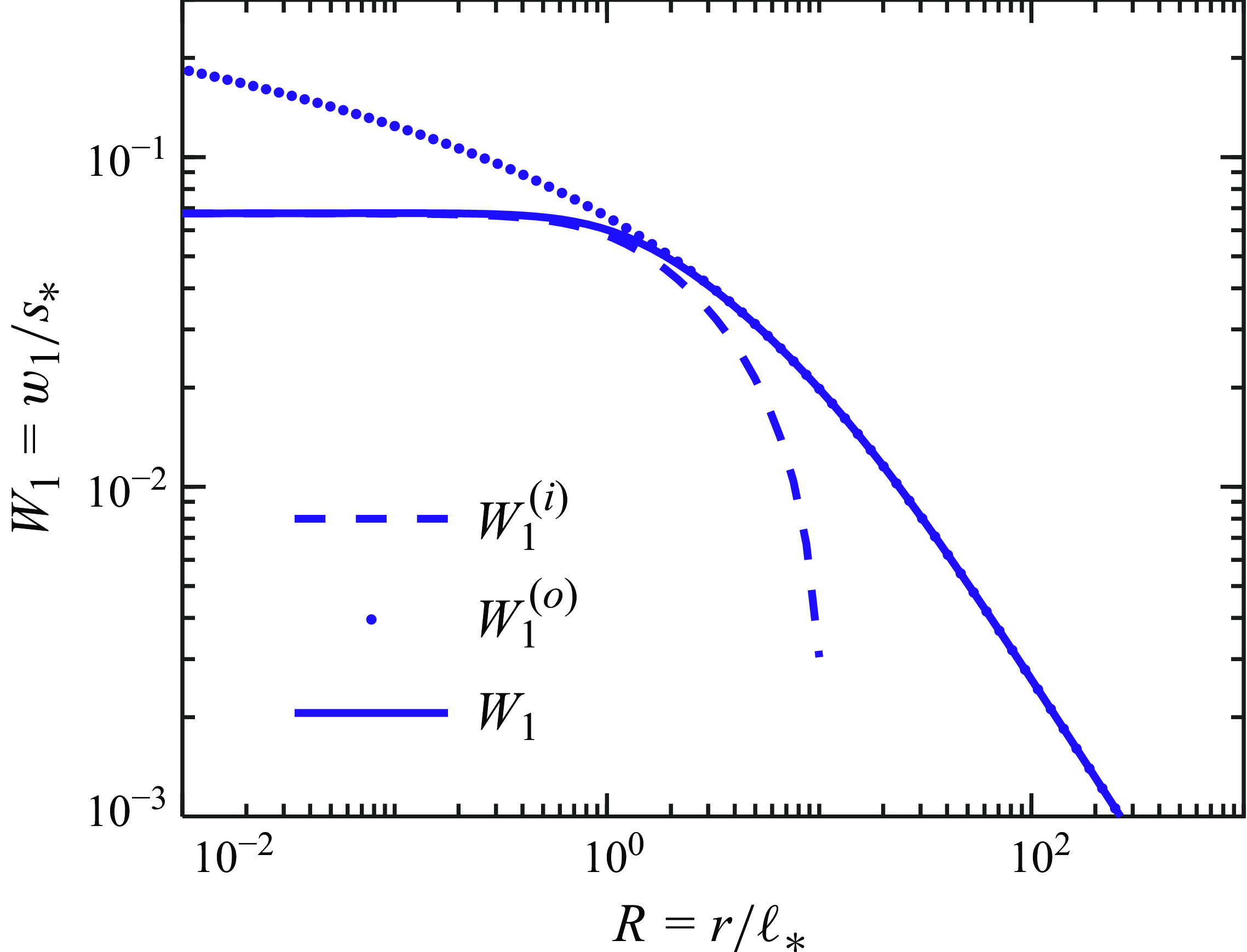
 $W_1^{(i)}(R) \propto -\ln R$
when
 $R \to \infty$
and hence an ‘outer’ solution is required to ensure consistency over the entire domain. Physically, this inner solution neglects elasticity and thus represents a balance between Laplace pressure and the zeroth-order vdW pressure (Dai & Vella Reference Dai and Vella2022). The solution to (3.12) is given by
 \begin{equation} W_1^{(i)}(R) = C_1 + \frac {1}{6 \unicode{x03C0} S(2 + \alpha S)\,W_s(R)} + \frac {\left [2 + 6 \unicode{x03C0} C_2 S^2 (2 + \alpha S)^2 \right] \ln R - \ln W_s(R)}{6 \unicode{x03C0} S^2 (2 + \alpha S)^2}, \end{equation}
where
 $W_s(R) = 2S + \alpha S^2 + R^2$
, and
 $C_1$
and
 $C_2$
are integration constants. Imposing the symmetry condition at the origin, i.e.
 $\lim _{R \to 0} W^{\prime}(R) = 0$
, gives
 $C_2 =$
 $-{1}/[{3\unicode{x03C0} S^2(2+\alpha S)^2}]$
.
To determine
 $C_1$
, we note that elasticity can eventually become important at large distances from the origin, playing a role in flattening the surface deformation similar to that of gravity. Indeed, the similar behaviour has been observed in the jump of an AFM probe to a liquid surface, where surface forces compete with gravity (Liu et al. Reference Liu, Bai, Xia and Ke2005; Quinn et al. Reference Quinn, Feng and Stone2013). We then rescale the radial variable in (3.11) as
 $\hat {R}=R/\Gamma$
and
 $\hat {\Xi }=\Gamma \Xi$
, resulting in
 \begin{equation} \hat {\Xi }\tilde{W}_1^{(o)}(\hat {\Xi }) + \hat {\Xi }^2\, \tilde{W}_1^{(o)}(\hat {\Xi }) = \frac {\hat {\Xi }^2\, \text{K}_2\left (\sqrt {S (2 + \alpha S)}\, \hat {\Xi }/\Gamma \right)}{6 \unicode{x03C0} S (2 + \alpha S)}, \end{equation}
which indicates that in the far-field limit (
 $\hat {R} \sim 1$
or
 $\hat {\Xi } \sim 1$
), elastic and surface forces are equally important. We solve (3.14) under the condition
 $\Gamma \gg 1$
, yielding the solution
 \begin{equation} {W}_1^{(o)}(\hat {R}) = \frac {\mathcal{G}\left ( {4}/{\hat {R}^2} \right)}{3 \unicode{x03C0} ^2 S^2 \left ( 2 + \alpha S \right)^2 \hat {R}}, \end{equation}
where
 $\mathcal{G}(x) = \text{MeijerG} ( \left \{ [0, {1}/{2}, {1}/{2}], [] \right \}, \left \{ [0], [] \right \}, \left \{ x \right \})$
, and
 $\text{MeijerG}$
represents the Meijer G function (§§ 5.3–5.6 in Bateman & Erdélyi Reference Bateman and Erdélyi1953). To match the inner solution with the outer solution, we impose
 \begin{equation} \lim _{R \to \infty } W_1^{(i)} = \lim _{\hat {R} \to 0} W_1^{(o)}, \end{equation}
which gives
 $C_1 = C_2 (\gamma _E - \log {2\Gamma })$
, where
 $\gamma _E$
is the Euler’s constant, with approximate value
 $0.577$
.
Finally, we obtain the valid first-order solution for the surface deformation of a surface-tension-dominated elastic substrate by combining the inner and outer solutions and subtracting their overlap (i.e. either side of (3.16)):
 \begin{align} W_1(R) ={} &\frac {1}{6\unicode{x03C0} S(2+\alpha S)(2S + \alpha S^2 + R^2)} \nonumber \\[5pt] &{} + \frac {2\Gamma \, \mathcal{G}\left ( {4\Gamma ^2}/{R^2} \right) - {\unicode{x03C0}R} \log {\left [ {(2S + \alpha S^2 + R^2)}/{R^2} \right]}}{6 \unicode{x03C0} ^2 S^2 (2 + \alpha S)^2 R}, \end{align}
which is plotted in figure 5. We compare this analytical solution to numerical results computed with
 $\epsilon = 0.1$
for various probe–substrate gaps, as shown in figure 6(a). Consistent with (3.14), the length scale over which the deformation decays is proportional to
 $\Gamma$
(see the comparison between
 $\Gamma = 10^2$
and
 $\Gamma = 10^4$
in figure 6
a).

The effect of surface tension on the substrate deformation. (a) Surface deformation of the elastic substrate for various gap values. Markers denote numerical results, while solid curves represent the analytical solution from (3.17). (b) Gap as a function of the cantilever position for rigid (black curve, given by (2.10)) and deformable (red curve, given by (3.18)) substrates. Calculations are performed with
 $\alpha = 0.01$
,
 $\epsilon = 0.05$
and
 $\Gamma = 10^2$
(or
 $\Gamma = 10^4$
, with corresponding markers and curves displayed with partial transparency).

Interestingly, increasing
 $\Gamma$
appears to enhance the extent of substrate deformation, thereby slightly advancing the jump-to-contact point, as illustrated in figure 6(a,b). However, this observation is nuanced: while
 $\epsilon$
is held constant,
 $\Gamma$
is embedded in the definition of
 $\epsilon$
through (2.21). Thus the results indeed suggest that surface tension mitigates premature jumps. Specifically, with
 $\epsilon$
fixed at
 $0.1$
, increasing
 $\Gamma$
from
 $10^2$
to
 $10^4$
needs to amplify the Hamaker constant (i.e. the strength of vdW interaction) by a factor of
 $100$
, yet the jump-to-contact point shifts only modestly (figure 6). This subtle behaviour arises because the prefactors for the jump-to-contact point depend on
 $\Gamma$
logarithmically, as will be discussed shortly.
(a) The gap of the probe above the undeformed substrate and (b) the net attractive vdW force between the probe and the deformed substrate as functions of the cantilever position for substrates with different compliances
 $\epsilon$
(encoded in the colour bar). Coloured empty markers represent numerical calculations, while the coloured curves are based on (2.15) and (3.18). The leftmost curve in black represents the rigid limit, provided by (2.10). Here,
 $\alpha =0.01$
and
 $\Gamma =10$
.

To gain analytical insight into the jump-to-contact point, we use (3.6) to calculate
 $P_1$
, and subsequently employ (2.16) to calculate the total vdW force, given by
 \begin{align} \mathcal{F} ={}& \frac {2}{3 S^2 (2 + \alpha S)^2} \nonumber \\ &{}+ \left [12\log {\frac {4\Gamma ^2}{2S+\alpha S^2}} + 5 - 24\gamma _E + \frac {9\unicode{x03C0} \sqrt {2S+\alpha S^2}}{2\Gamma }\right]\frac {(1+\alpha S)\epsilon }{27 \unicode{x03C0} S^5 (2 + \alpha S)^5}. \end{align}
This relation, combined with (2.15), provides accurate predictions of the gap–cantilever position and force–cantilever position relationships for
 $\epsilon \ll 1$
and
 $\Gamma \gg 1$
, as demonstrated in figure 7. Furthermore, for
 $\alpha \ll 1$
, we are able to derive simple expressions for the critical gap, force and cantilever position at the onset of the jump as
 \begin{align} S_c &\approx \frac {1}{3^{1/3}} \left (1 {- \frac {\alpha }{6 \times 3^{1/3}}} + \frac {120\log \Gamma + 20\log {24} + 37 - 120\gamma _E}{288\unicode{x03C0} }\epsilon \right),\\[-5pt]\nonumber \end{align}
 \begin{align} \mathcal{F}_c &\approx \frac {1}{24^{1/3}} \left (1 {- \frac {2\times 3^{2/3}}{9}\alpha } - \frac {\log \Gamma + 0.41}{3\unicode{x03C0} }\epsilon \right),\\[-5pt]\nonumber \end{align}
 \begin{align} D_c &\approx \frac {3^{2/3}}{2} \left (1 {- \frac {\alpha }{3}} + \frac {\log \Gamma + 0.16}{6\unicode{x03C0} }\epsilon \right), \end{align}
respectively. Again, the decimal coefficients here are exact values. These analytical solutions show good agreement with numerical results for substrates with low effective compliance, as illustrated in figure 8(a,b).
The jump-to-contact point for substrates with large surface tensions (
 $\Gamma \gg 1$
). (a) Critical attractive vdW force
 $\mathcal{F}_c$
and (b) critical cantilever position
 $D_c$
as functions of the effective compliance of the substrate
 $\epsilon$
, for various surface tensions. Markers represent numerical calculations, while curves correspond to the analytical solutions given in (3.19a
–
c
). The values of corresponding surface tension are encoded in the colour bar. Note that the solid curves are valid only for large
 $\Gamma$
. Here,
 $\alpha =0.01$
is used in numerics.

4. The effect of velocity of approach
Having examined the phenomenon of premature jump-to-contact on a deformable substrate in a static context, we now shift our focus to the influence of probe approach dynamics, which can play a role in liquid environment AFM on soft biological materials (Krieg et al. Reference Krieg, Fläschner, Alsteens, Gaub, Roos, Wuite, Gaub, Gerber, Dufrêne and Müller2019; Viljoen et al. Reference Viljoen, Mathelié-Guinlet, Ray, Strohmeyer, Oh, Hinterdorfer, Müller, Alsteens and Dufrêne2021). In typical AFM operations, the probe or its supporting cantilever comes into contact with the substrate at a controlled velocity (Baró & Reifenberger Reference Baró and Reifenberger2012). To characterise how the resulting viscous resistance affects the jump behaviour, it is natural to compare the characteristic hydrodynamic pressure (scaling as
 $\mu v_* \ell _*^2 / s_*^3$
) with the vdW pressure (scaling as
 $A / s_*^3$
), leading to a dimensionless speed of approach
 \begin{equation} \lambda = \frac {36\unicode{x03C0} \mu v_* \ell _*^2}{A}, \end{equation}
where
 $\mu$
is the liquid’s dynamic viscosity,
 $v_*$
is the characteristic approach velocity, and the factor
 $36\unicode{x03C0}$
is introduced for notational convenience in the subsequent discussion.
In typical contact-mode colloidal probe AFM measurements for studying soft materials (Baró & Reifenberger Reference Baró and Reifenberger2012; Wegmann et al. Reference Wegmann, Medalsy, Mandelkow and Müller2013; Zhang et al. Reference Zhang, Bertin, Arshad, Raphaël, Salez and Maali2020), the characteristic approach velocity
 $v_*$
is approximately
 $1 \,{\unicode{x03BC} \mathrm{m\, s}^{-1}}$
. Considering a Hamaker constant
 $A = 10^{-20}\,\mathrm{J}$
, water viscosity
 $\mu \approx 1\ \mathrm{mPa \ s}$
, cantilever stiffness
 $k = 0.1\,\mathrm{N\, m^{-1}}$
, and a spherical probe with radius
 $R_s \lesssim 10\,{\unicode{x03BC} \mathrm{m}}$
, the characteristic scales are approximately
 $s_* \approx 10\,\mathrm{nm}$
and
 $\ell _* \approx 316\,\mathrm{nm}$
, yielding
 $\lambda \lesssim 1$
. For tapping-mode or high-speed AFM experiments conducted in more viscous liquids (Baró & Reifenberger Reference Baró and Reifenberger2012; Zhang et al. Reference Zhang, Bertin, Essink, Zhang, Fares, Shen, Bickel, Salez and Maali2023), however,
 $\lambda$
can increase significantly, reaching values greater than 100.
We expect that the viscous effect can be considered negligible when
 $\lambda \ll 1$
. To justify this, we investigate the dynamic version of the jump-to-contact problem by neglecting the small terms associated with
 $\alpha$
in the vdW and Laplace pressure for simplicity (Bertin Reference Bertin2024; Rallabandi Reference Rallabandi2024). In this case, the probe profile is well approximated by a paraboloid, and the gap between the probe and deformed substrate evolves over time:
 \begin{equation} h(r,t)=s(t)+\frac {r^2}{2R_s}-w(r,t). \end{equation}
By applying the no-slip boundary condition at both the probe and the elastic substrate, the Stokes equation for the flow can be approximated using lubrication theory (Leal Reference Leal2007), which governs the evolution of the gap profile as
 \begin{equation} \frac {\partial h}{\partial t} = \boldsymbol{\nabla} \cdot \left [\frac {h^3(r,t)}{12\mu }\, \boldsymbol{\nabla} q(r,t)\right], \end{equation}
after neglecting higher-order terms of the order
 $\alpha ^2$
(Tavakol et al. Reference Tavakol, Froehlicher, Holmes and Stone2017), where
 $q(r,t)$
is the pressure within the liquid. The inertial effects in the system are neglected here, though they might become significant in tapping-mode AFM experiments or during the impact process that occurs after the jump-to-contact point (Zheng, Griffiths & Stone Reference Zheng, Griffiths and Stone2015; Beaty & Lister Reference Beaty and Lister2023). The normal traction on the substrate can then then expressed as
 \begin{equation} \sigma _{zz}(r, z=0, t) = p(r,t) - q(r,t) + \gamma \frac {\partial ^2 w(r,t)}{\partial r^2}, \end{equation}
where the attractive vdW pressure for
 $\alpha \to 0$
simplifies to
 \begin{equation} p(r,t) = \frac {A}{6\unicode{x03C0} \,h^3(r,t)}. \end{equation}
We neglect the influence of shear traction on the normal surface deformation of the substrate, and assume that the mechanical response of the substrate is instantaneous (Davis et al. Reference Davis, Serayssol and Hinch1986; Juel, Pihler-Puzović & Heil Reference Juel, Pihler-Puzović and Heil2018; Bertin et al. Reference Bertin, Amarouchene, Raphaël and Salez2022; Poulain & Carlson Reference Poulain and Carlson2022). Under this assumption, the linear elasticity solution remains valid, with
 $\sigma _{zz}$
as defined in (4.4).
Aligning with the non-dimensionalisation used in the preceding sections, we adopt the following additional rescaling:
 \begin{equation} T = \frac {tv_*}{s_*}, \quad Q = \frac {q s_*^3}{A}, \quad \tilde{Q} = \frac {\mathcal{H}_0[q]\, s_*^2}{A \ell _*^2}. \end{equation}
With these definitions, the governing equations become
 \begin{equation} \lambda \frac {\partial H}{\partial T} = \frac {3\unicode{x03C0} }{R} \frac {\partial }{\partial R} \left (R H^3 \frac {\partial Q}{\partial R}\right) \end{equation}
and
 \begin{equation} H(R,T) = S(T) + \frac {1}{2}R^2 - W(R,T), \end{equation}
where the substrate deformation satisfies
 \begin{equation} \Xi \tilde{W}(\Xi,T) + \Gamma \Xi ^2\, \tilde{W}(\Xi,T) = (1 + \Gamma) \epsilon \left [\tilde{P}(R,T) - \tilde{Q}(R,T)\right] \end{equation}
and
 \begin{equation} P(R,T) = H^{-3}(R,T). \end{equation}
The total attractive force between the probe and the substrate, incorporating both intermolecular and hydrodynamic interactions, is
 \begin{equation} F(T) = 2\unicode{x03C0} \int _0^\infty \left [P(R,T) - Q(R,T)\right] R \, \mathrm{d}R. \end{equation}
In this dynamic problem, the approach of the probe
 $S(T)$
is usually controlled or modulated by the position of the cantilever holder
 $D(T)$
according to (2.15):
 \begin{equation} D(T) = S(T) + F(T). \end{equation}
Combining the perturbation analysis applied to the static problem in the preceding section and the dynamic soft lubrication problem outlined in Bertin et al. (Reference Bertin, Amarouchene, Raphaël and Salez2022) and Jha et al. (Reference Jha, Amarouchene and Salez2024), we apply the perturbation structure
 \begin{equation} V(R,T) = V_0(R,T) + \epsilon\, V_1(R,T) + O(\epsilon ^2), \end{equation}
where
 $V$
represents the surface deformation
 $W$
, the vdW pressure
 $P$
, or the hydrodynamic pressure
 $Q$
. At the
 $\epsilon ^0$
order, the problem corresponds to a rigid probe approaching a rigid wall. Consequently, the zeroth-order deformation and vdW interaction are identical to those provided in (3.5):
 \begin{equation} W_0 = 0, \quad P_0(R,T) = \frac {4}{3\unicode{x03C0} (2S + R^2)^3}. \end{equation}
The zeroth-order hydrodynamic pressure is governed by
 \begin{equation} \lambda \dot {S} = \frac {3\unicode{x03C0} }{R} \frac {\partial }{\partial R} \left [ R \left ( S + \frac {1}{2}R^2 \right)^3 \frac {\partial Q_0}{\partial R} \right], \end{equation}
yielding
 \begin{equation} Q_0(R,T) = \frac {-\lambda \dot {S}}{3\unicode{x03C0} (2S + R^2)^2}, \end{equation}
which matches the result presented in (3.3) of Bertin et al. (Reference Bertin, Amarouchene, Raphaël and Salez2022). Substituting these solutions into (4.11) and (4.12), we obtain
 \begin{equation} D(T) = S + \frac {1}{6S^2} + \lambda S \dot {S}, \quad \mathcal{F}(T) = \frac {1 + \lambda S \dot {S}}{6 S^2}. \end{equation}
This result represents the combined contributions of vdW forces between a sphere and a rigid wall under the Derjaguin assumption (Hamaker Reference Hamaker1937) and the classical Reynolds force for a sphere approaching a rigid wall immersed in a viscous liquid. Clearly, the vdW contribution dominates at smaller separations due to its stronger dependence on the gap thickness, whereas the Reynolds force becomes significant at higher approach velocities (i.e. larger
 $\lambda$
).
Delayed jump-to-contact on a rigid substrate. (a) The probe–substrate gap and (b) the net attractive force on the probe as functions of the cantilever position for different approaching velocities
 $\lambda$
(indicated by the colour bar). The rightmost black curve represents the static case, while the opaque coloured curves correspond to calculations with constant
 $\dot {D} = -1$
, and the partially transparent coloured curves correspond to
 $\dot {S} = -1$
.

In figure 9, we show the
 $S{-}D$
and
 $\mathcal{F}{-}D$
relations by solving (4.17) with constant probe velocity (
 $\dot {S} = -1$
) and constant cantilever velocity (
 $\dot {D} = -1$
). The results are similar when the probe is relatively far from the substrate. However, the constant probe velocity case shows a clear jump-to-contact point, after which the cantilever must be pulled back to maintain the constant probe velocity. In contrast, the jump point is blurred in the constant cantilever velocity case (which is more common in experiments). In both cases, the ‘stable’ part of the results converges to the static case (black curves) as
 $\lambda \ll 1$
.
An important observation in figure 9(b) is that viscous resistance contributes to delaying the jump-to-contact point, with this effect becoming more pronounced as
 $\lambda$
increases. Specifically, when
 $\lambda \gtrsim 1$
, the hydrodynamic pressure dominates the vdW attraction, causing the overall force on the probe to become repulsive during the initial stages of the approach. As the approach continues, the force may transition to less repulsive or attractive, eventually triggering the jump. This behaviour qualitatively resembles previous liquid environment AFM measurements on biological materials (e.g. figure S1 in Wegmann et al. Reference Wegmann, Medalsy, Mandelkow and Müller2013). It should be noted that even in the absence of viscous effects, the jump can still be delayed due to the inertial effects of the cantilever, as reported in related dynamic fold bifurcation problems, such as the snap-through instability of slender structures (Gomez et al. Reference Gomez, Moulton and Vella2017a
; Liu, Gomez & Vella Reference Liu, Gomez and Vella2021).
We continue to briefly discuss the first-order solution (see details in Appendix A). As expected, the substrate deformation is not vanishing, and its direction transitions from upwards to downwards when
 $\lambda \gtrsim 1$
, regardless of whether the substrate has small or large surface tension. To illustrate this impact on the jump-to-contact, we present the first-order
 $\mathcal{F}{-}S$
solution for a substrate with small surface tension:
 \begin{align} \mathcal{F}(T) \approx{} & \frac {1}{6 S^2} + \frac {\lambda \dot {S}}{6 S} \nonumber \\ & {}+ \frac {1}{36\unicode{x03C0} \, S^{11/2}} \Big (1.2075 + 2.1915 \lambda S \dot {S} + 0.7411 \lambda ^2 S^2 \dot {S}^2 - 0.3271 \lambda ^2 S^3 \ddot {S} \Big) \epsilon. \end{align}
The decimal coefficients here are obtained numerically by solving the decoupled differential equation (see (A7) and (A8) in Appendix A). Interestingly, in contrast to earlier elastohydrodynamic collision studies of elastic slabs (e.g. Davis et al. Reference Davis, Serayssol and Hinch1986; Essink et al. Reference Essink, Pandey, Karpitschka, Venner and Snoeijer2021; Bertin et al. Reference Bertin, Amarouchene, Raphaël and Salez2022; Poulain & Carlson Reference Poulain and Carlson2022), (4.18) predicts additional
 $1/S^{11/2}$
and
 $\dot S/S^{9/2}$
contributions due to vdW pressure, which become significant at small gaps and moderate approach speeds. Note that the solution for substrates with large surface tension is implicit due to the additional controlling parameter
 $\Gamma$
. Interestingly, an acceleration term emerges in (4.18) when the system is controlled by a constant cantilever velocity.
Delayed jump-to-contact on a deformable substrate: the overall attractive force on the probe as functions of the cantilever position for different approaching velocities
 $\lambda$
(indicated by the colour bar). The black curves represent the static case, while the coloured curves correspond to calculations with constant
 $\dot {D} = -1$
according to (4.18). Here, we used
 $\epsilon =1$
for opaque curves, and
 $\epsilon =0$
for partially transparent curves.

In figure 10, we present the results obtained under constant cantilever velocity for both the deformable case (
 $\epsilon = 1$
for opaque curves) and the rigid case (
 $\epsilon = 0$
for partially transparent curves). It is evident that the premature jump-to-contact due to substrate deformation is delayed by hydrodynamic resistance, such that the premature effect is almost completely screened by the delaying effect when
 $\lambda \sim 1$
. This result suggests that in typical tapping-mode AFM measurements, where
 $\lambda$
can reach up to 100, force curves provide limited reliability for interpreting vdW forces. In contrast, in contact-mode AFM measurements, where
 $\lambda$
can be controlled well below 1, the influence of viscous forces during the approach phase may be negligible. Consequently, the static solutions presented in the preceding section could be useful for interpreting AFM experiments conducted at very slow approach velocities.
5. Conclusions
We have theoretically investigated the van der Waals (vdW) force-induced jump-to-contact behaviour of a spherical AFM probe on a deformable substrate, accounting for the effect of solid surface tension. In a static scenario, our analysis reveals that the jump-to-contact can occur prematurely compared to the rigid case, primarily due to substrate deformation. This study focuses on relatively compliant cantilevers to which the AFM probe is attached, allowing for small substrate deformations that are resisted by both elasticity and surface tension in response to vdW attraction from the probe. This assumption enables the derivation of relatively simple analytical solutions for the substrate deformation as well as the critical jump-to-contact force and displacement, which can aid in interpreting AFM measurements.
Additionally, we explore the effect of the approaching dynamics of the probe and cantilever, showing that these dynamics can delay the jump-to-contact event. For the analytical solutions derived in the static setting to be applicable, it is crucial that the parameter defined in (4.1) is much smaller than unity. Alternatively, if the approach velocity can be well controlled in experiments, then our dynamic analysis may help to decipher the complex interplay between the vdW and hydrodynamic pressures during the approaching process. For instance, the dynamic force–distance curves in our results resemble previous observations where the force felt by the probe can initially be repulsive and transition to attractive before the jump in dynamic measurements. Exploring this behaviour could enable more accurate determination of the so-called contact point or zero-displacement point in liquid environment AFM measurements, which has been a key issue in mechanobiology (Krieg et al. Reference Krieg, Fläschner, Alsteens, Gaub, Roos, Wuite, Gaub, Gerber, Dufrêne and Müller2019).
We note that while the analysis in this work is based on the semi-infinite elastic slab model, we believe that the underlying concepts can be extended to other geometries and configurations, such as elastic coatings and slender structures including cell membranes and elastic sheets, as discussed in recent works on fluid–elastic interactions (Daddi-Moussa-Ider et al. Reference Daddi-Moussa-Ider, Rallabandi, Gekle and Stone2018; Chandler & Vella Reference Chandler and Vella2020; Bertin et al. Reference Bertin, Amarouchene, Raphaël and Salez2022; Rallabandi Reference Rallabandi2024). Additionally, there may be several interesting extensions of this work, including the consideration of electric double-layer forces, inertia of the cantilever, and the viscoelastic and poroelastic properties of the test material, which could significantly influence the results in real liquid environment AFM experiments.
Acknowledgements
The author thanks D. Vella for helpful comments and suggestions on an earlier version of the paper, and Y. Man for useful discussions.
Funding
This work was supported by the National Natural Science Foundation of China (grant nos 12372103 and 12432003).
Declaration of interests
The author reports no conflict of interest.
Data availability statement
The numerical code used in this study will be made openly available on GitHub after the publication of this work.
Appendix A. First-order dynamics solution
Substituting (4.13) into (4.9) and rearranging terms, we derive the order-
 $\epsilon$
solution for the surface deformation of the elastic substrate in a Hankel domain:
 \begin{equation} \tilde{W}_1 = \frac {1 + \Gamma }{\Xi + \Gamma \Xi ^2}(\tilde{P}_0-\tilde{Q}_0). \end{equation}
Likewise, since directly performing the inverse transform of this equation is infeasible, we derive the analytical solutions for small and large surface tensions. Specifically, for
 $\Gamma \to 0$
, the solution is given by
 \begin{equation} W_1(R,T)=\frac { 2 \left [(1 + \lambda S \dot {S})+2S/\left (2S + R^2 \right)\right] \, \mathcal{E}\left ({-R^2}/{2S}\right) - \mathcal{K}\left ({-R^2}/{2S}\right) }{ 12 \sqrt {2}\, \unicode{x03C0} S^{3/2} \left (2S + R^2\right) }, \end{equation}
and for
 $\Gamma \to \infty$
, we use the method of matched asymptotic expansions to obtain
 \begin{equation} W_1(R,T) = \frac {1}{12\unicode{x03C0} S(2S + R^2)} + \frac {2\Gamma \, \mathcal{G}\left ( {4\Gamma ^2}/{R^2} \right) - \unicode{x03C0} R \log {\left [ {(2S + R^2)}/{R^2} \right]}}{24 \unicode{x03C0} ^2 S^2 R/(1 + \lambda S \dot S)}. \end{equation}
Surface deformation of an elastic substrate subjected to the combined effects of vdW, Laplace and hydrodynamic pressures at order
 $\epsilon$
. (a) Plot of (A2) with
 $\Gamma = 0$
. (b) Plot of (A3) with
 $\Gamma = 100$
. The value of
 $\lambda$
for each coloured curve is indicated in the colour bar (the black curve represents the quasi-static case). In both cases,
 $S=10$
and
 $\dot S = -1$
are used for demonstration.

The first-order solution for the vdW force can be obtained directly by substituting (4.13) into (4.10):
 \begin{equation} P_1(R,T) = \frac {8}{\unicode{x03C0} (2S +R^2)^4}W_1(R,T), \end{equation}
which could be negative when
 $\lambda \gtrsim 1$
, as shown in figure 11. Therefore, the correction to the interaction force in the rigid limit in (4.17) due to vdW forces can be given by integrating (A4) over the entire domain, which is
 \begin{equation} \mathcal{F}_{P_1}=\frac {35 \unicode{x03C0} (27 + 20 \lambda S \dot {S})}{196608 \sqrt {2} S^{11/2}}\epsilon \end{equation}
for small surface tensions, and
 \begin{equation} \mathcal{F}_{P_1}=\frac {\left (24\log \Gamma -13\right) + 2\left (12\log \Gamma -11\right)\lambda S \dot S}{864\unicode{x03C0} S^5}\epsilon \end{equation}
for large surface tensions.
Similarly, the first-order hydrodynamic pressure satisfies the equation obtained by substituting (4.13) into (4.7), i.e.
 \begin{equation} {\lambda }\frac {\partial W_1}{\partial T} +\frac {3\unicode{x03C0} }{R}\frac {\partial }{\partial R}\left [R\left (S+\frac {1}{2}R^2\right)^3\frac {\partial Q_1}{\partial R} - 3R\left (S+\frac {1}{2}R^2\right)^2\frac {\partial Q_0}{\partial R}W_1\right]=0. \end{equation}
This ordinary differential equation can be solved numerically under the boundary conditions
 $Q_1(\infty, T) = 0$
and
 $Q_1(0, T)$
being finite. Interestingly, the term
 $\partial W_1/\partial T$
in (A7) suggests that
 $\ddot {S}$
can also contribute to the first-order liquid pressure, which has also been observed in the soft lubrication problem discussed in Bertin et al. (Reference Bertin, Amarouchene, Raphaël and Salez2022). Specifically, summing
 $Q_1$
gives
 \begin{equation} \mathcal{F}_{Q_1} \approx -\frac {\lambda }{100 S^{5/2}} \left (1.1468\frac {\dot {S}}{S^{2}} + 0.6553\frac {\lambda {\dot {S}}^2}{S} - 0.2892 \lambda \ddot {S}\right)\epsilon \end{equation}
for the case of zero surface tension (
 $\Gamma = 0$
). Compared with the results in Bertin et al. (Reference Bertin, Amarouchene, Raphaël and Salez2022), the prefactors of the second and third terms in (A8) are identical (after substituting (2.21) and (4.1)), while the term associated with
 $\dot {S}$
is new and arises from the superposition of vdW forces. The force–gap relation in (4.18) can then be obtained by combining the rigid limit solution (4.17) with (A8) and (A5).