


1.0 Introduction
In spite of the fact that a major thread in my career in aerodynamics has been related to numerical simulation of vortical flow for high angle-of-attack and manoeuvering aircraft (which is probably why I was chosen to give this lecture), that is not what I have decided to concentrate on in this lecture. That topic has been very well covered in recent years by several colleagues of mine, including John Lamar of NASA Langley in 2011, Jim Luckring of NASA Langley in 2017, Art Rizzi of KTH in 2021 and most recently by Marilyn Smith of Georgia Tech in 2023. When you also realise that the very first Lanchester Memorial Lecture was given by Theodore von Karman of Caltech in 1957, you can imagine that the field of vortical flow aerodynamics has already been well covered in these lectures.
Luckily for me, however, another major thread throughout my career has been aerodynamics education, including how it should evolve as we move through the 21st century. Therefore, I have chosen to concentrate on this aspect of Lanchester’s career and work, rather than the topics that have been so well written about in the past. But before diving into details about aerodynamics we should get to know the namesake of this lecture a little better.
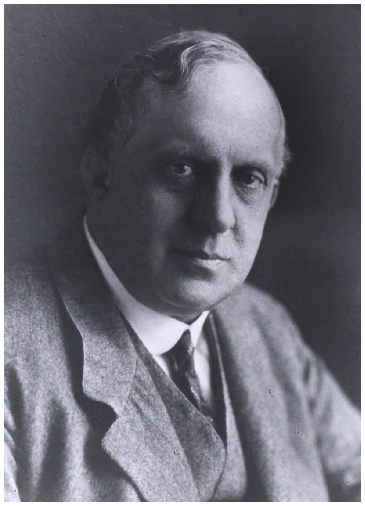
Frederick W. Lanchester (1868–1946, see photograph in Fig. 1) was an English engineer and inventor who worked, at various times during his career, on developing concepts for automobiles, boats and airplanes, as well as on what we now call operations research. ‘He was, by any definition a polymath – a creative genius also ahead of his time and often struggling to get the “establishment” to catch up or take notice’ [Reference Hughes1]. Lanchester was born in South London and grew up near Brighton. He studied engineering at the Hartley Institution in Southampton (now the University of Southampton) and later the Normal School of Science in Kensington (later the Royal College of Science and now Imperial College), while also attending night classes at the Finsbury Technical College (which was closed in 1926 and incorporated into Imperial College). His first job after university was as a draughtsman, followed quickly by a succession of jobs at engine and automobile manufacturing firms.
A photo of Frederick W. Lanchester taken in 1933 (Birmingham Science Museum, Creative Commons Attribution-Share Alike 4.0 International license).
If you were to create a curriculum vitae for Lanchester, the education and professional experience sections would look something like this (although there is a great deal of temporal overlap among the various professional positions, as well as a fair amount of disagreement among various sources about dates) [Reference Ricardo2–Reference Ackroyd4]:
-
• Hartley Institution, Southampton, 1883–1885
-
• Normal School of Science, Kensington, 1885–1888
-
• Patent Office, London, Draughtsman,1888–1889
-
• Forward Gas Engine Company, Birmingham, Works Manager, 1889–1895
-
• Lanchester Engine Company, Birmingham, Co-owner, 1895–1904
-
• The Lanchester Motor Company, Ltd, Birmingham, General Manager, 1904–1929
-
• The Daimler Motor Company, Coventry, Consultant, 1909–1929
At this point you might wonder why Lanchester ever became known for aerodynamics, especially if you take a look at some of the advances he contributed to the development of engines and automobiles while working at these companies. According to Theodore von Karman, his contributions to the development of automobiles and other mechanical fields include [Reference Von Karman3]:
an engine starter, surface carburettor, an epicyclic speed-change gear, a pre-selector gear, and apparatus for measuring worm gear efficiency, a wire wheel, an electric ignition device, a direct-driven top gear and normal transmission on a rear axle, a crankshaft damper, an harmonic balancer, a process for the manufacture of piston rings, a pendulum accelerometer for measuring and recording traction and braking effort, a gyroscopic true plumb and turn indicator (widely used by the Royal Air Force in the First World War) and an acoustic loud speaker and ‘diffractaphone aperture’ for use both in concert halls and in the open air.
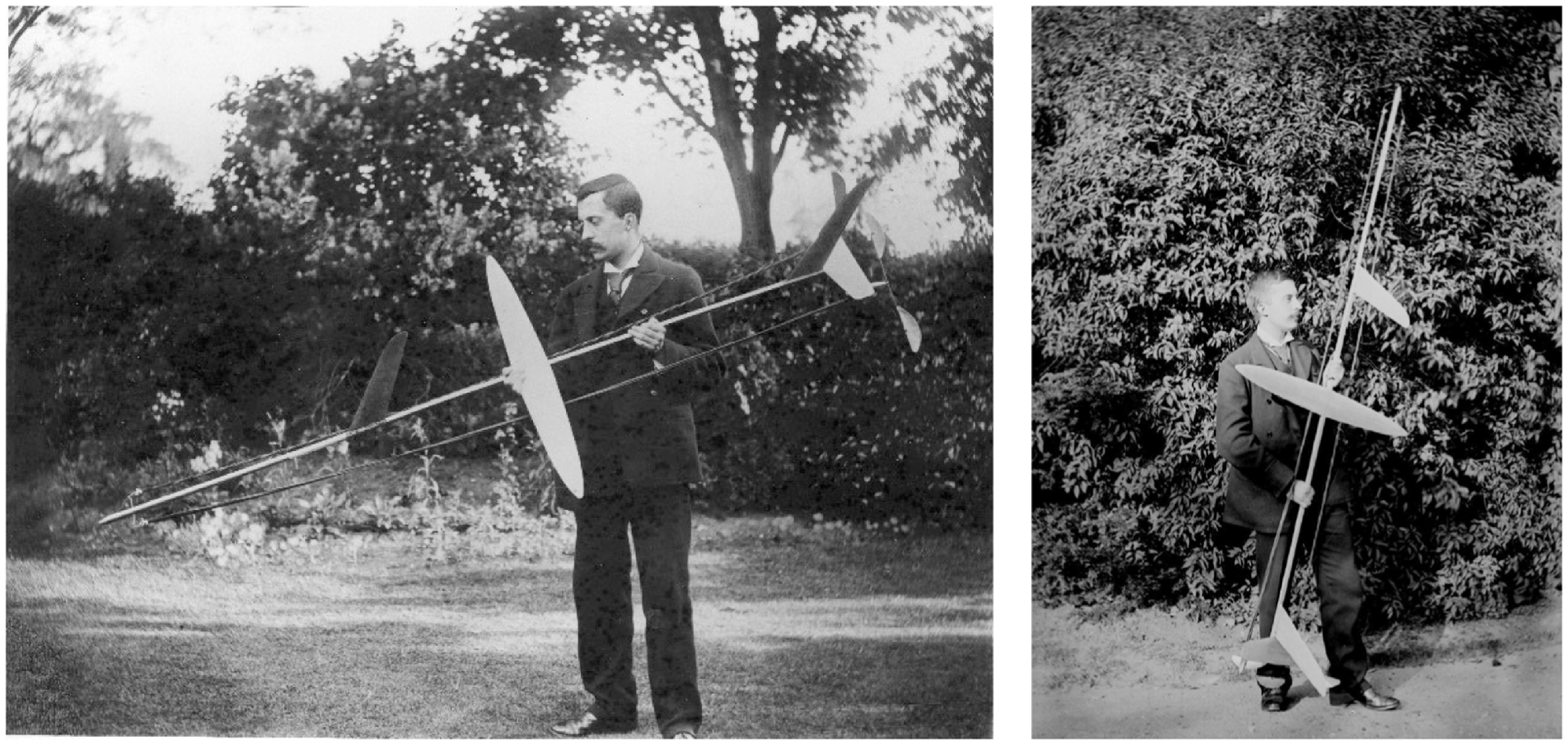
Overlapping his work for the various motor and automobile companies, Lanchester also started working on flying machines in the early 1890s, almost as a hobby, as related by Capt J. Laurence Pritchard: ‘My serious study of the problem of mechanical flight began in the year 1891’ [Reference Von Karman3]. In the early years his studies of flight began with hand-held gliders (see Fig. 2), and later he started designing larger aircraft. However, his most important aviation-related contributions were in aerodynamics, flight mechanics, and operations research. According to Prof. John Anderson: “He divided his time between designing and developing high-speed engines and carrying out aerodynamic experiments using model gliders. In particular, during 1891-2 he tested a series of aerofoils with curved shapes (i.e., cambered aerofoils)’ [Reference Anderson5]. We will go into Lanchester’s aerodynamics research in greater detail in later sections, but for now we can see that Lanchester was an automotive engineer by ‘day’ and an early aeronautical engineer by ‘night’ [Reference Anderson5].
Frederick W. Lanchester “with his 1894 powered model driven by twin pusher propellers powered by twisted skeins of india-rubber” [Reference Jarrett6] (left photo provided with permission from Philip Jarrett; right photo from Coventry University, Lanchester Interactive Archive, Creative Commons (BY-NC-ND) 4.0 License).
His contributions to both automotive and aeronautical engineering throughout his career led to many accolades and awards later in his life, ‘For Lanchester was a man ahead of his times and had to suffer all the frustrations that are the usual lot of such great minds’ [Reference McCloskey7]. Lanchester’s ‘lifetime achievement’ awards include [Reference McCloskey7]
-
• Fellow of the Royal Society
-
• Honorary Doctor of Laws, Birmingham University
-
• Honorary Member of the Institution of Mechanical Engineers
-
• Honorary Member and President of the Institution of Automotive Engineers
-
• Honorary Fellow of the Royal Aeronautical Society
-
• Member of Advisory Committee on Aeronautics, 1909–1920
-
• Gold Medal of the Royal Aeronautical Society (1926)
-
• Daniel Guggenheim Medal (1931)
-
• Ewing Medal of the Institution of Civil Engineers (1941)
-
• James Watt International Medal of the Institution of Mechanical Engineers (1945)
While we certainly could spend a great deal of time discovering more about the automotive side of Lanchester’s career, the remainder of the paper will be devoted to his aeronautical, and primarily aerodynamic, contributions.
2.0 Lanchester’s contributions to aerodynamics
In order to more fully understand Lanchester’s contributions to aerodynamics, it will be helpful to first understand how his efforts were received at the time. Once we see the challenges that he faced with publishing his work in the 1890s and into the early 20th century, we can then better understand his contributions and ideas that we know more clearly today. The publication of Aerodynamics will hopefully then make much better sense within this historical context.
2.1 Comments on Lanchester’s inability to publish
Frederick Lanchester is now well known as one of the great contributors to aerodynamic concepts and understanding. Unfortunately, as we will see, he was not well known for aerodynamics at the time he was conducting experiments. We will probably never know everything that Lanchester achieved while developing model flyers in the last decade of the 19th century, primarily because he was not able to get his work published until many years after he developed his concepts and theories. His earliest efforts at characterising vortical flow and lift had been presented in 1894 as a lecture during a meeting of the Birmingham Natural History and Philosophical Society, but his work was not accepted for publication by that society, and that lecture was subsequently never published (and no copies have been found since then) [Reference Von Karman3]. Prof. Theodore von Karman of Caltech, on the occasion of the first Lanchester Memorial Lecture in 1958, said that Lanchester revised his 1894 paper and submitted it to The Royal Society, which recommended it be submitted to The Physical Society, where it was rejected [Reference Von Karman3].
Lanchester did eventually succeed in being published by a Royal Society, however, but it was the Royal Society of Arts in 1909 [Reference Lanchester8]. This publication took place after he had completed publishing his two books on aerial flight: Aerodynamics in 1907 [Reference Lanchester9] and Aerodonetics in 1908 [Reference Lanchester10]. Apparently, not many people had been aware of Lanchester’s contributions to aerodynamics in the time between 1894 and 1907. For example, Prof Richard Southwell said in 1930, ‘I shall suggest that the kernel of all we yet know of fundamental aerodynamic theory was there to read in 1914’ [Reference Southwell11]. To which J. Laurence Pritchard wrote in 1957, ‘One might add, in 1894, if Lanchester had been listened to’ [Reference Pritchard12].
So why were Lanchester’s papers not being published in a timely fashion, even though we can now see they contained many important ideas? While there is little direct evidence for the reasons behind his inability to publish, there are many ideas and observations on the topic. In his book Aviation: An Historical Survey, Charles H. Gibbs-Smith said it was because his writing style was difficult to understand [Reference Gibbs-Smith13].
Prof Ludwig Prandtl of the University of Göttingen, on the occasion of giving the Wilbur Wright Memorial Lecture to the Royal Aeronautical Society in 1927, told the audience (which included Lanchester, which must have been awkward): ‘The truth of the matter, however, is that Lanchester’s treatment is difficult to follow, since it makes a very great demand on the reader’s intuitive perceptions, and only because we had been working on similar lines were we able to grasp Lanchester’s meaning at once’ [Reference Prandtl14].
Prof Theodore von Karman offers another reason for the lack of understanding towards Lanchester’s early papers:
One reason for the lack of understanding of Lanchester’s presentation might have been his particular liking for his own terminology, which was different from that commonly used. The term ‘sweep’ was his own creation; the cyclic or circulatory motion called flow with circulation in the modern scientific literature he called ‘peripteral motion’. He also talked of a ‘forced wave’, although the analogy, of a flow round an aerofoil with wave motion, consists only of the fact that in both cases no energy is taken from the fluid or transferred to it [Reference Von Karman3].
Prof von Karman also comments that another fundamental reason for the misunderstanding of Lanchester’s work was that no accepted aerodynamic theory existed in the late 19th century and into the early 20th century, which made it difficult for reviewers to understand Lanchester’s ideas [Reference Von Karman3]. In other words, von Karman is saying that there really was not a solid, well accepted, theory of aerodynamics prior to Lanchester, and the various theories and fluid flow concepts that existed at the time were contradictory and lacking in accuracy. Reviewers of his paper or articles might have seen him as someone presenting ‘just another aerodynamic theory’, among so many other competing theories, which could easily be dismissed.
Von Karman adds yet another possible reason for the lack of publications when he states Lanchester just was not ‘mathematical’ enough, especially when compared with the work being developed on similar topics at the time by Martin Kutta [Reference Kutta15] and Nikolai Joukowski [Reference Joukowski16]:
It is true that because of this coincidence of their efforts (Kutta, Joukowski and Lanchester) and Lanchester’s delayed publications, Lanchester’s clear priority for the circulation theory of sustentation was questioned; but it must be conceded that the mathematical theory gave more than he was able to deduce from his more or less qualitative arguments. On the other hand, he recognised the general mechanism of the lift and the induced drag also for the case of the aerofoil with finite span, for which the systematic mathematical theory needed approximately another decade of development [Reference Von Karman3].
In other words, while the more mathematical treatments of Kutta and Joukowski (who were both mathematicians/scientists) presented a theory for aerofoil circulation and lift, it was Lanchester’s description that made the theory practical and useful for airplanes. Also, Lanchester was the only one who extended the lift concept to three-dimensional wings, which was crucial for designing aircraft.
Philip Jarrett also has put forth a reason for Lanchester’s lack of publication success in an article from 2014: ‘Lanchester and The Great Divide’ [Reference Jarrett6]. In that paper Jarrett builds the case for a disconnect between those that were conducting mathematical/scientific research in the field of aeronautics and those that were interested in designing and building airplanes.
What I refer to as the ‘great divide’ is the perceived lack of communication and understanding in aviation’s very early years between those who made theoretical and scientific studies of aerodynamics but failed to comprehend the requirements of a practical aeroplane, and those who actually built and tried to fly aeroplanes but lacked scientific expertise [Reference Jarrett6].
Certainly, the issues with translation and understanding of papers and books from English to German and vice versa caused delays in comprehension. Von Karman stated that this was definitely a problem for Prandtl, but it was not a problem at all for Carl Runge:
How far Prandtl’s work at Gottingen had been influenced by Lanchester’s ideas in the development of his own theories was an often discussed question. I was a graduate student at the University when Lanchester visited Gottingen for the first time. Lanchester had much closer relations with Carl Runge, Prandtl’s colleague teaching applied mathematics, for the reason that Runge spoke perfect English and Prandtl had difficulty expressing himself in that language [Reference Von Karman3].
Another, less flattering, reason for Lanchester’s failure to publish is also possible. Could it be that Lanchester, being an engineer from the automotive industry, was the object of some level of class bias towards his work? Was he being ‘looked down upon’ because he was a practical engineer and not a mathematician or scientist? Certainly that is a possibility, and while some limited evidence exists for this perception, we probably will never know how much this impacted his ability to publish.
I hesitate to bring up a final possible reason for Lanchester’s inability to publish papers, one that does not seem to be mentioned very often in other sources. In reading Lanchester’s letters [17], (Ref. 17 is a treasure trove of Lanchester’s files, letter, and photos) I have noticed that he could, at times, be quite ‘prickly’ when communicating with people. While the catalog of letters I viewed did not include the letters he wrote while he was trying to publish his paper in 1894, they did include, among quite a few others, a letter he wrote to Prof A.V. Hill (the Secretary of the Royal Society) in 1939 [17]. In that letter Lanchester recounts the problems he had publishing his 1894 paper:
It is forty-five years ago that I submitted the draft of a paper to Professor Poynting, (then Member of council R.S.) in the hope that he would think the matter of sufficient importance to make the basis of a paper to the Royal, but being rather backward in the art of writing elegant English I felt that it would not come up to the then standard required, I had hoped that I might get a few hints or help in making it presentable. That paper contained the discovery of that which is now known as the circulation theory of sustentation in flight. At Poynting’s suggestion I sent it to the Physical Society, whose referee turned it down, and whose Secretary (Mr. Elder) added on his own account a little ‘damn’ in agreement with the referee! I published it in my book “Aerodynamics” some thirteen years later, it was even then still new. … Then finding they were wrong owing to its universal acceptance on the Continent and in America and Japan they had to accept the theory, but to save face they attributed it to Prandtl, who had developed it with suitable mathematical embroidery. They called it Prandtl’s theory. … All this did me immeasurable harm, and the R.S. did not show up well. There is some humor in the fact that I was given my Fellowship of the Society as an engineer, not in recognition of my work in aerodynamics at all! [17]
Lanchester was obviously still hurt by the events that had taken place many decades before, but he was also willing to lash out against people he believed had harmed him. In other parts of the same letter, Lanchester can be seen to be sarcastic, belittling and even rude. Of course, it is hard to put myself in his position and to fully understand what it must have felt like to have your work rejected. I would hope, however, that a more positive approach to communicating with others might have made the situation more productive.
A similar situation took place in 1908 when Lanchester decided to travel to France to meet and interact with Wilbur Wright, who was at Le Mans demonstrating the Wright Model A airplane (Wilbur Wright conducted his first flight in France in August 1908). Apparently that meeting did not go as well as planned, as evidenced by a letter Wilbur Wright wrote to Lanchester in January 1909 – the letter is shown in Fig. 3 [17].
Wilbur Wright’s letter to F.W. Lanchester, written 4 January 1909 from Le Mans, France [17] (Coventry University, Lanchester Interactive Archive, Creative Commons (BY-NC-ND) 4.0 License).
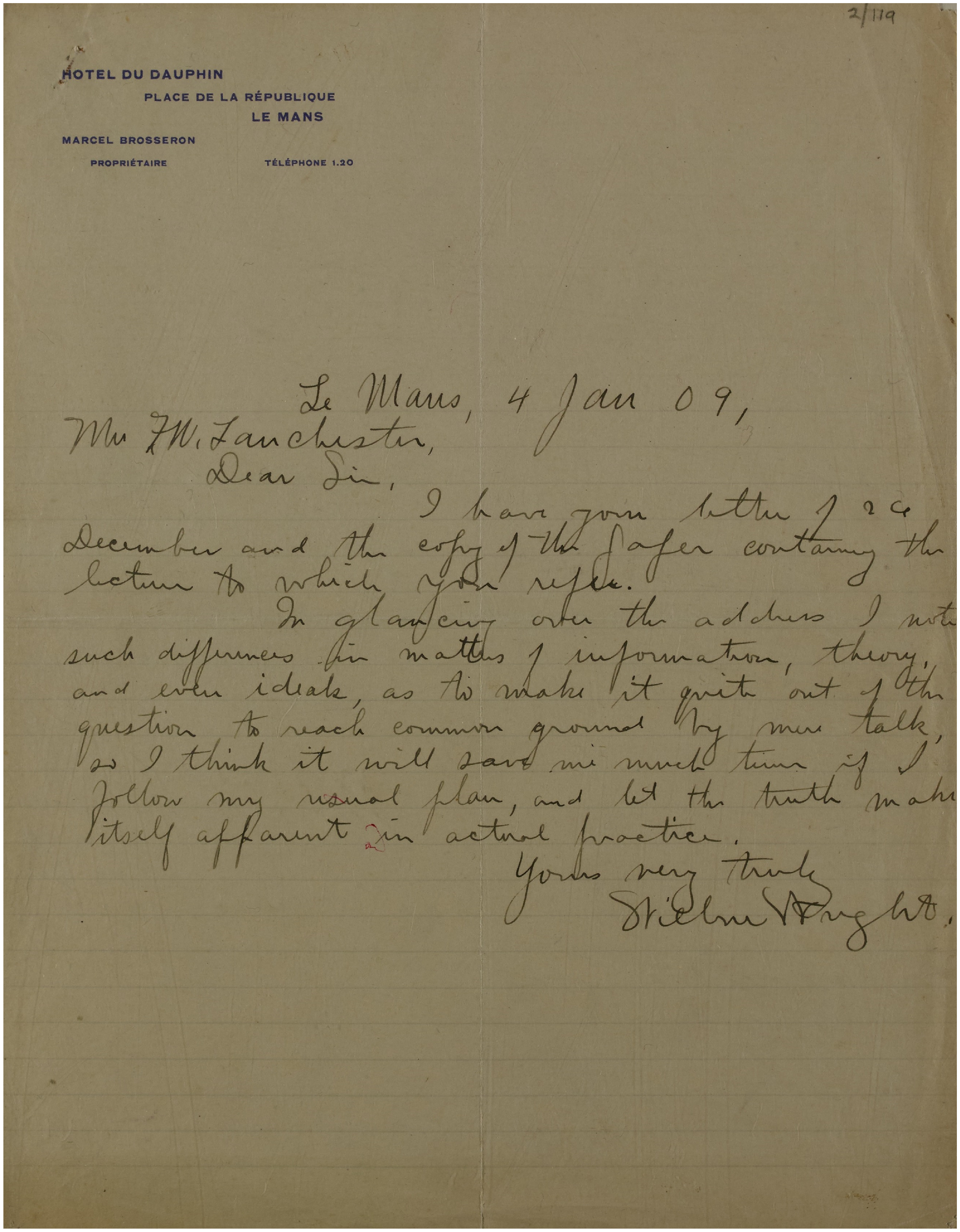
A transcription of the letter follows:
Dear Sir,
I have your letter of 29 December and the copy of the paper containing the lecture to which you refer.
In glancing over the address I note such differences in matters of information, theory, and even ideals, as to make it quite out of the question to reach common ground by mere talk, so I think it will save me much time if I follow my usual plan, and let the truth make itself apparent in actual practice.
Very truly yours,
Wilbur Wright
Unfortunately, I could not find a copy of Lanchester’s letter of 29 December 1908, and their conversations during the time when the two met in France in August 1908 seems to have been limited to details about the design and manufacture of the Wright aircraft (of which Lanchester apparently was not overly impressed) [Reference Lanchester18]. We do know, however, what Lanchester thought about the meeting in France, because he described it in a letter to Col. J. Fullerton, the Secretary of the Aeronautical Society of Great Britain, written 24 November 1908 [17] (see Fig. 4).
Letter from Lanchester to Col. J. Fullerton, dated 24 November 1908 [17] (Coventry University, Lanchester Interactive Archive, Creative Commons (BY-NC-ND) 4.0 License).
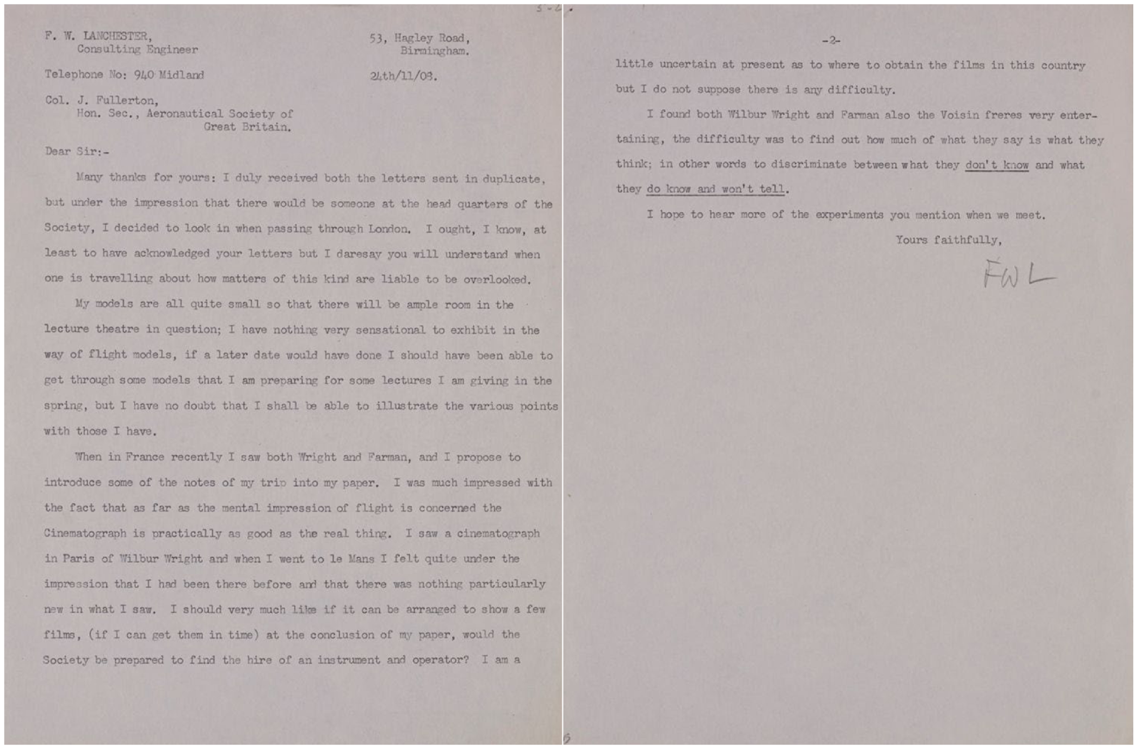
The letter begins with some small talk and details regarding a lecture Lanchester was to give at the society. Lanchester then begins talking about his meeting with Wilbur Wright:
When in France recently I saw both Wright and Farman, [the pilot of the Voisin airplane] and I propose to introduce some of the notes of my trip into my paper. I was much impressed by the fact that as far as the mental impression of flight is concerned the Cinematograph is practically as good as the real thing. I saw a cinematograph in Paris of Wilbur Wright and when I went to le Mans I felt quite under the impression that I had been there before and that there was nothing particularly new in what I saw [17].
And then a few sentences later:
I found both Wilbur Wright and Farman also the Voisin freres [the brothers Gabriel and Charles Voisin who were French aircraft manufacturers] very entertaining, the difficulty was to find out how much of what they say is what they think: in other words to discriminate between what they don’t know and what they do know and won’t tell [17].
Of course, Lanchester is describing the well-known reticence of Wilbur Wright to talk very much, especially about the details of his airplanes. Lanchester did state in his lecture that, ‘the reticence shown is perhaps no more than might be anticipated’ [Reference Lanchester18], so it is a little difficult to know his true feelings on that matter. Also, in Lanchester’s lecture about the Wright airplane [Reference Lanchester18] in December 1908 he includes many technical details that he learned from Wilbur Wright during his visit to Le Mans: ‘Mr Wright has admitted (at least to the author) that his gliding angle is about 7 degrees; this, at a gross weight of 1,100lbs., gives 140lbs thrust required, and at 58ft per sec, the thrust h.p. becomes 14.5’ [Reference Lanchester18].
Jarrett notes an important difference between Lanchester and Wilbur Wright [Reference Jarrett6]:
Two principal features made Lanchester favour the Voisin aeroplane over the Wright: the French machine incorporated ‘heavy engineering’ techniques in its construction and was designed to be inherently stable, both factors that would have appealed to an automobile engineer who had experimented only with ‘passive’ model aircraft, whereas the American aircraft, designed by bicycle designers and manufacturers and evolved from experiments with full-size manned gliders, was simple and light in structure and designed to be unstable.
Lanchester did make several positive statements about the Wright airplane in his lecture, including, ‘On the whole the advantage certainly rests with the Wright machine from the aerodynamic standpoint’ [Reference Lanchester18]. In general, however, Lanchester had issues with the Wright approach and their airplane and was not afraid to voice those opinions in public. Apparently, Wilbur Wright also disagreed with Lanchester’s approach, but voiced his position in private.
The list of reasons for Lanchester’s inability to publish his work is long, with issues put forth from many well-known figures in the development of aerodynamic theories and concepts. Constraints such as Lanchester’s writing style and use of his own terminology, his non-theoretical approach, the lack of solid pre-existing theory, issues with the slowness of translation of books and papers between England and Germany, possible publication bias, and even Lanchester’s personality all might have contributed to his problems with publication. We will probably never know for sure which of these reasons is a main culprit, but it is possible that some or all of them may be correct to one extent or another. What we do know is that Lanchester made contributions to aerodynamics that we recognise today as being very important, even if others at the time did not recognise his contributions, for whatever reasons.
2.2 Lanchester’s writing style in historical context
Before proceeding to the specific details of Lanchester’s contributions to aerodynamic theory, I thought I would take a moment to investigate the theory that Lanchester was not a very clear writer. Certainly, Von Karman’s objections to Lanchester’s proclivity for making up his own technical terms is valid, but I wonder how correct the ‘bad writer’ complaint really is. As an un-scientific test for determining Lanchester’s writing ability (and how well he was understood), I have chosen three writing excerpts, all from the prefaces of early 20th century editions of fluids/aerodynamics books, and all written by native English speakers. Without looking ahead to the answer, perhaps you can determine which of these three excerpts was written by Lanchester:
Excerpt A: ‘Some memoirs deal chiefly with questions of mathematical method and so fall outside the scope of this book; others though physically important hardly admit of a condensed analysis; others, again, owing to the multiplicity of publications, may unfortunately have been overlooked’.
Excerpt B: ‘The commonly distinctive feature of a modern mathematical treatise, in any branch of physics, is that the investigation of any problem is initially conducted on the widest and most comprehensive basis, equations first being obtained in their most general form, the simpler and more obvious cases being allowed to follow naturally, the greater including the less’.
Excerpt C: ‘The way to this has not been pointed out by established treatises on aero-dynamics, whose fundamental postulates, like those of any other established science, may be held to contain implicitly all truths deducible from them, but which are far from being of practical help here, that from these postulates previous writers of the highest repute have deduced the directly opposite con-clusion, that mechanical flight is practically impossible’.
To the early 21st century reader these three early 20th century excerpts certainly could all seem somewhat challenging to read. While we can only depend on what people said at the time, as discussed above in great detail, we do not know if people at that time believed anyone writing on aerodynamics was ‘easy to read’. So, which of these three excerpts were written by Lanchester? Excerpt A is from Horace Lamb’s book Hydrodynamics (4th Edition, 1916) [Reference Lamb19], Excerpt B is from William Lanchester’s book Aerodynamics (1907) [Reference Lanchester9] and Excerpt C is from Samuel Langley’s Experiments in Aerodynamics (2nd Edition, 1902) [Reference Langley20]. How did you do? Can you, as an early 21st century reader, tell the difference between these early 20th century technical writers? I have to admit that I cannot – they all require great attention and patience to understand in my opinion!
2.3 Aerofoil and wing theory
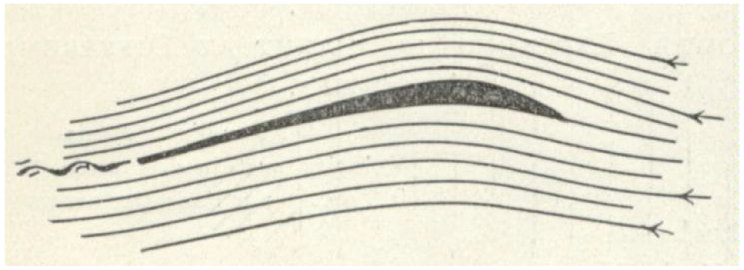
Lanchester spent a great deal of time experimenting with aerofoils and wings in the last decade of the 19th century. He was, by no means, unique in this endeavour, since many others had done the same thing before (and after) him, including Sir George Cayley, Otto Lilienthal, Horatio Phillips, Samuel Langley, Hiram Maxim, A.F. Zahm and the Wright Brothers (among others) [Reference Pritchard12]. What separated Lanchester from the others who were working on aerofoils, was his ability to deduce a theoretical cause for the performance of aerofoils, specifically the concept of circulation. Figure 5 shows a sketch made by Lanchester of flow over an aerofoil, and it includes several important concepts related to aerofoil aerodynamics: (1) the flow is changing direction upstream of the aerofoil; (2) the streamlines over the upper surface of the aerofoil are closer together than those under the lower surface (causing the flow to be faster over the upper surface than the lower surface); (3) the flow continues on a downward path after the trailing edge; and (4) there is a small wake behind the trailing edge due to viscous effects [Reference McCloskey7, Reference Lanchester21].
Flow over an aerofoil as described by Lanchester (public domain) [Reference Lanchester8].
Lanchester’s aerofoils, which had been developed based on his physical understanding described above, were actually very good aerofoils compared with other shapes of the time. Anderson points out that, ‘Lanchester’s aerofoil designs, obtained from his calculations, were tested in Prandtl’s wind tunnel at Göttingen University in 1912–13 and were found to produce a lift-to-drag ratio of 17; that was a 10% improvement over other models tested in that wind tunnel up to that time’ [Reference Anderson5].
While others had come up with some of these circulation concepts from a purely theoretical perspective, Lanchester saw what no one else at the time could understand: the two dimensional flow around the aerofoil section, when applied to a three dimensional wing, created a circulation pattern that continued in the vicinity of the wing tip, as shown in Fig. 6 (which he called ‘peripteral motion’). His final ‘visual’ representation of this three dimensional flow is shown in Fig. 7, which has been reproduced a great deal since the publication of his book.
The circulation of flow around the aerofoil and in the vicinity of the wing tip (public domain) [Reference Lanchester8].
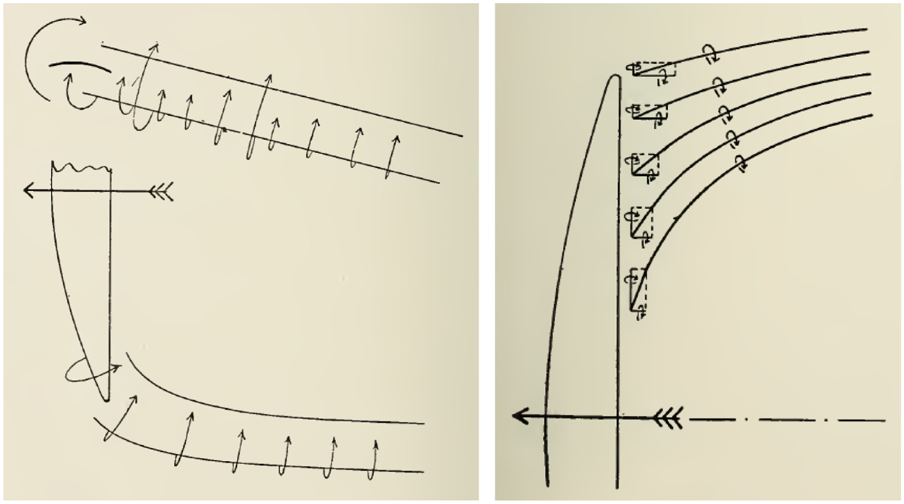
Lanchester’s sketch of the wing-tip vortex system (public domain) [Reference Lanchester8].

In addition, Lanchester knew that the three-dimensional flow in the vicinity of the wing tip would alter the flow of the aerofoils on the wing, thus creating an additional component of drag that we now call ‘induced’ or ‘vortex’ drag. He not only foresaw this new component of drag, he developed a way to find the magnitude of the induced drag using energy arguments. This clearly put Lanchester outside the realm of ‘tinkerer’ or ‘inventor’ and into the realm of a true aerodynamicist. Theodore von Karman later observed that,
Although Lanchester never arrived at a complete theory of the finite wing, as did Prandtl several years later, the presentation of the problem in his book published in 1907 contains practically all the elements necessary for such a theory. He recognised that: –
-
1. In the case of a finite aspect ratio wing two vortex trunks are formed at the wing tips.
-
2. Each vortex trunk consists of a system composed of many individual vortices leaving the trailing edge of the wing along the span.
-
3. The kinetic energy contained in this vortex system must be renewed by expending work continuously during uniform flight.
-
4. The work required to maintain the same sustentation increases with decreasing aspect ratio [Reference Von Karman3].
Even Prandtl saw it necessary to comment on Lanchester’s contributions to wing theory upon the occasion of giving the Wilbur Wright Memorial Lecture in 1927.
In England you refer to it as ‘the Lanchester-Prandtl theory’, and quite rightly so, because Lanchester obtained independently an important part of the results. He commenced working on the subject before I did, and this no doubt led people to believe that Lanchester’s investigations, as set out in 1907 in his Aerodynamics, led me to the ideas upon which the aerofoil theory was based. But this was not the case. The necessary ideas upon which to build up that theory, so far as these ideas are comprised in Lanchester’s book, had already occurred to me before I saw the book. In support of this statement, I should like to point out that as a matter of fact we in Germany were better able to understand Lanchester’s book when it appeared than you in England. English scientific men, indeed, have been reproached for the fact that they paid no attention to the theories expounded by their own countryman, whereas the Germans studied them closely and derived considerable benefit therefrom [Reference Prandtl14].
Of course, Prandtl had to make sure there was no uncertainty in the uniqueness of his approach to wing theory, and that it had not been influenced by Lanchester’s approach. But he also was quick to give Lanchester credit for the first concept of wing theory, one which Prandtl would spend many years working on before coming up with his well-known ‘lifting line’ theory. Prandtl, however, notes that it was not the researchers in Germany who snubbed Lanchester and his concepts, but rather it was the scientific community in England who had done that.
2.4 Boundary layers, skin friction, and aircraft resistance
Boundary layer concepts represent yet another topic that linked Lanchester and Prandtl, since Lanchester also came up with concepts for boundary layers around the same time as Prandtl. According to J.A.D. Ackroyd, ‘Independently of Prandtl, Lanchester (1907) also proposes a boundary layer concept, although it seems unlikely that a date can be given to its inception. All that seems to be known is that, in 1905, Lanchester was carrying out experiments with model gliders with the specific intention of estimating skin friction’ [Reference Ackroyd4]. So, once again, Lanchester and Prandtl are linked, and in this case Lanchester had a practical application in mind, rather than just the development of a theory.
While there is a great deal of detail to Lanchester’s concepts for boundary layers [Reference Ackroyd4], the real goal of his work was to find relationships for laminar and turbulent skin friction drag so he could determine the resistance of a wing at various velocities. Lanchester states in Aerodynamics that part of his motivation is the observation by Samuel Langley that,
these new experiments, (and theory also when reviewed in their light), show that if in such aerial motion, there be given a plane of fixed size and weight, inclined at such an angle, and moved forward at such a speed, that it shall be sustained in horizontal flight, then the more rapid the motion is, the less will be the power required to support and advance it. This statement may, I am aware, present an appearance so paradoxical that the reader may ask himself if he has rightly understood it [Reference Langley20].
Lanchester completely agreed with the final sentence of Langley, but completely disagreed with the notion that power required would be less at higher velocities. Lanchester dives a little deeper into the experiments of Langley and finds that the following statement of Langley when discussing his experiments for a resultant pressure recorder, helps explain the paradox: ‘We may remark that they [his experimental data] incidentally show that the effect of the air friction is wholly insensible in such experiments as these’ [Reference Langley20]. At this point, Lanchester then states, ‘Unfortunately, the optimistic view propounded by Langley in his so-called law has not been realised. It is founded on the supposed negligibility of skin-friction, a supposition that can be no longer upheld’ [Reference Lanchester8].
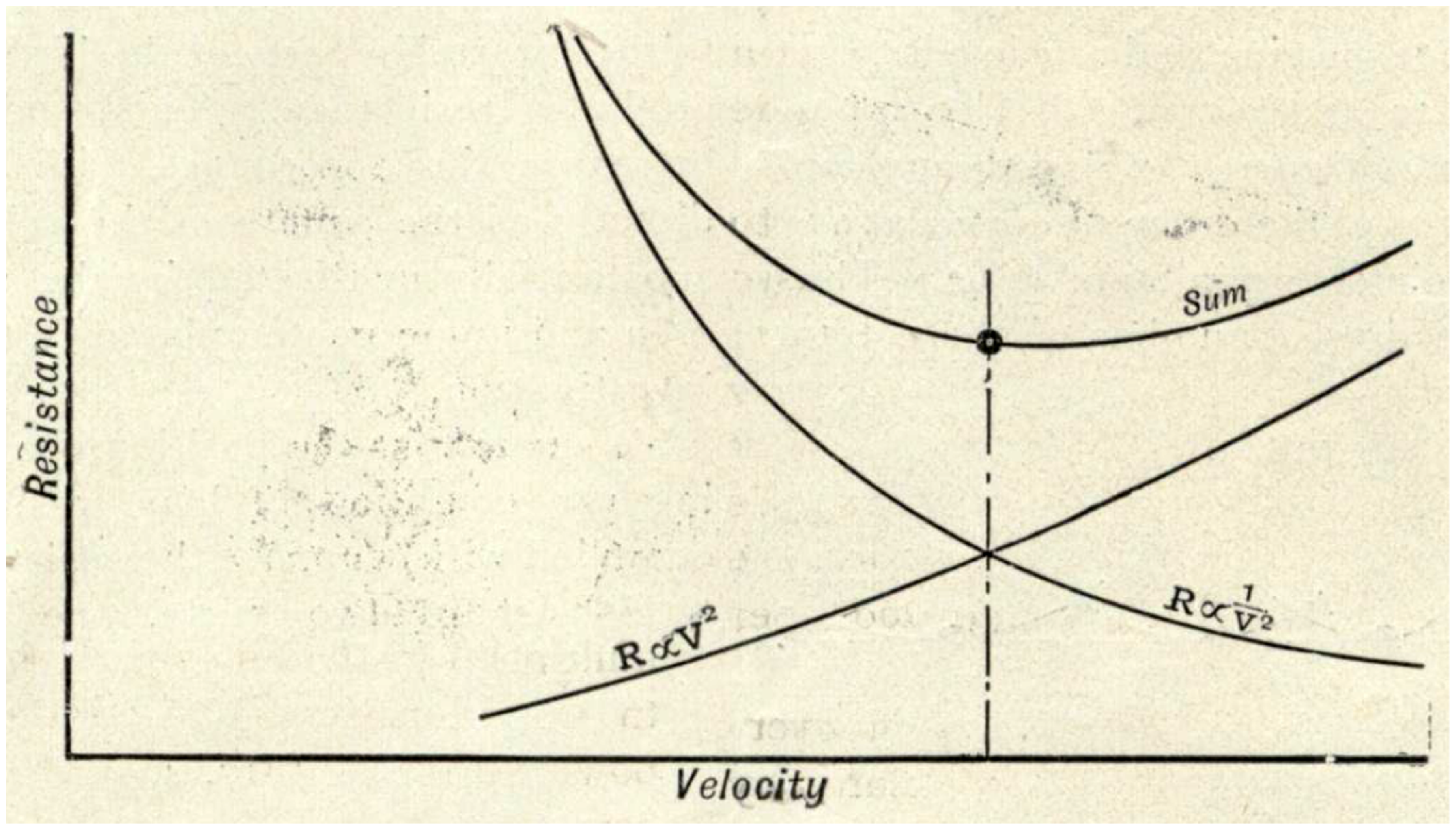
At this point in his lecture, Lanchester then proceeded to develop the basic variation of resistance (drag) as a function of velocity, as shown in Fig. 8. He describes his experimental results showing that friction creates resistance proportional to V2, and then he goes on to describe how other experiments show that another component of resistance (what we now call induced drag or vortex drag) varies with 1/V2. Plotting both components of resistance shows one increasing steadily while the other decreases steadily. Lanchester goes on to say,
Now here a fact is apparent of which the proof is given in the author’s work; [Lanchester refers to Ref. Reference Lanchester9, his book Aerodynamics] the total resistance has a minimum value at the point where the two different kinds of resistance are equal one to the other; thus, if an aeronaut requires to travel from one point to some other point on the least supply of fuel he will choose the velocity corresponding to this point of least resistance [Reference Lanchester8].
Resistance as a function of velocity for an airplane (public domain) [Reference Lanchester8].
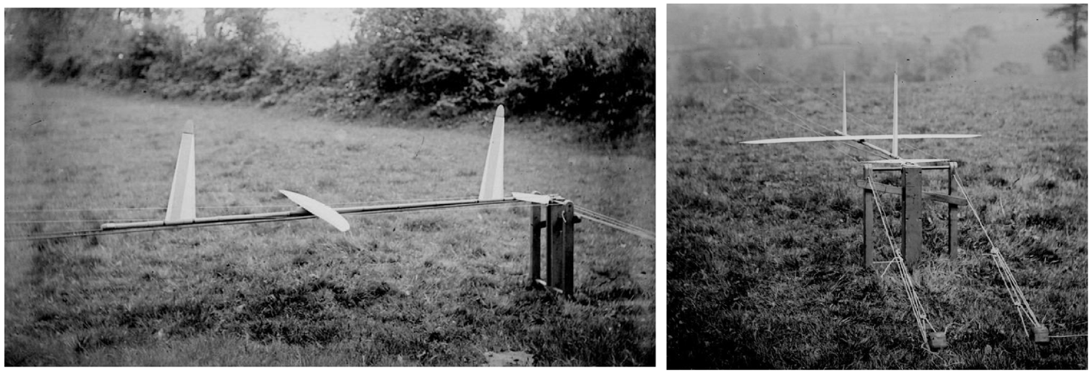
Photographs of Lanchester’s model airplane catapult system from 1894 (Coventry University, Lanchester Interactive Archive, Creative Commons (BY-NC-ND) 4.0 License).
This is, of course, how we view the situation today, and can be mathematically shown that the minimum thrust required for flight takes place when the parasite drag equals the drag due to lift. Furthermore, this point is where the lift-to-drag ratio (L/D) is maximised for the airplane. Lanchester had understood this ‘dual nature’ of resistance long before others.
2.5 Flight performance and mechanics
Lanchester had been conducting model airplane flights for many years (see Fig. 2 for pictures of his models), designed to measure model weight, speed, distance, velocity, flight path, glide angle, etc. He could use the model system to test different wing planforms and aerofoil shapes if needed. He launched his airplane models using a catapult system (see Fig. 9) and states that the flights began about 15 feet above the ground from a rear first story window of his house that faced west, down a slope of approximately 1 in 25 [Reference Lanchester10]. He states that about 20–30 flights were made during June and July of 1894, and he presents data for six of those flights. He had become quite adept at understanding the efficiency of an airplane wing and aerofoils through these measurements and comparing the performance of various shapes with each other. He used the data he collected for determining skin friction drag, lift-to-drag ratios, wing performance, etc. He also made observations of flight paths (with help from some ‘observers’ who sketched the vertical flight paths); Fig. 10 shows results from these flights (numbered 1–6). Anyone who has flown balsa wood gliders will recognise some of these flight paths. The recorded six flights made by Lanchester in 1894 using models with and without propellers are (references to figure numbers in the description are from Lanchester’s book, but have been retained here and in the figures for clarity) [Reference Lanchester10]:
Referring to Fig. 23 (plan of sight) we have Flight No. 1, date not recorded, weight of aerodone entered as 1¼lbs.; very light wind; distance about 200 yards. This is the initial flight made with first model.
Flight No. 2, June 24th (?), weight 1lb. 7 oz.; distance 280 or 290 yards; high wind with powerful gusts, probably about 30mh direction W.S.W.; time of flight 27 seconds. A magnificent flight, remarkable ‘switch-back’ flight path, distance, relative to wind, probably over 600 yards.
Flight No. 3, June 24th (?), same aerodone as Flight No. 2; distance 200 yards; time of flight 73 seconds; very light wind. Velocity = 55mh (Fig. 26).
Flight No. 4, same as No. 3, distance 200 yards; time not recorded (Fig. 26).
Flight No. 5, June 24th (?), same aerodone as Flight No. 2; distance 150 yards; time of flight 53 seconds; very light wind. Velocity = 56mh.
Flight No. 6, July 3rd, twin screw aerodrome; weight 2½lbs.; distance 133 yards; no appreciable wind; time of flight 44 seconds? (Fig. 27).”
Schematic of flight paths for six model airplane flights in 1894; Lanchester Aerodonetics, Fig. 23 (public domain) [Reference Lanchester10].

At this point a note should be made about the unusual forward vertical stabiliser seen in Fig. 8. Modern aircraft designers would look at this surface and realise it would create negative lateral stability to the aircraft (and wonder why Lanchester did not understand that fact). In fact, however, Lanchester fully understood that this surface was de-stabilising, and he used it for two purposes [Reference Lanchester9]:
-
• They allowed Lanchester to control the location of the lateral neutral point in order to easily change the stability of his flying model without changing the baseline model.
-
• These surfaces were the ‘test’ surfaces for each flight of the same aerodone – the baseline configuration provided a defined lift and drag, and the introduction of wing planforms and/or aerofoil shapes with these vertical surfaces allowed for measuring incremental lift and drag (and impact on performance).
Notice that Flights 2, 3 and 4 started fairly straight, and then Flight 2 started to turn toward the left as it traveled ‘280 or 290 yards’ (as shown in Fig. 9). What you do not see in Fig. 9, however, is what the airplane is doing in the pitch plane as it progresses along the horizontal flight path. For this information look at the top half of Fig. 10, which shows the recorded vertical flight path for Flight 2, and notice that the airplane is going through three cycles of fairly significant pitch up/pitch down motion before it impacts the ground. Also note that Flight 2 took place in fairly strong winds with large gusts (Lanchester later describes the wind as a head wind). Vertical flight path information for Flights 3 and 4 are also shown in Fig. 11, but they did not exhibit this cyclic motion, although these flights were slightly shorter at about 200 yards and conducted in calm winds.
Vertical flight paths for Flights 2, 3, and 4; Lanchester Aerodonetics, Figs 25 and 26 (for some reason this figure was published at an angle to the page orientation in the original book, the orientation has been adjusted in this presentation) (public domain) [Reference Lanchester10].

Extended vertical flight paths for Flights 2, 3 and 4 shown with dotted lines (backward in time) and dashed lines (forward in time), with the ‘mean gliding path’ shown with the long dashed line; Lanchester Aerodonetics, Fig. 27 (public domain) [Reference Lanchester10].

Now Lanchester does something quite ingenious. Looking at the cyclic pitch motion for Flight 2 in Fig. 10, he extends the motion both forward and back from the observed flight test data (extrapolating around a flight path centreline) to come up with a longer flight test as shown in Fig. 12. Lanchester observes,
It is evident that the angle of the line of mean flight depends upon the design of the aerodone, the less the total resistance of the latter in proportion to its weight, the less the angle γ: this is a matter of aerodynamics. It is further evident that the greater the launching velocity the greater the distance at which the line of mean flight path passes vertically over the point of discharge, i.e., the greater the distance h in the figure [Reference Lanchester10].
Lanchester continues:
The examination of the behaviour of an aerodone in flight has in the foregoing demonstration been carried as far as has been found possible without a mathematical analysis; it now becomes necessary to adopt a more rigid line of treatment and to examine quantitatively the curves of flight and the conditions governing their form and permanence.
Lanchester then proceeds to perform this mathematical analysis assuming the airplane can be represented by a three degree-of-freedom longitudinal representation, and also assuming that the airplane loses no energy during the flight, but rather is able to trade kinetic energy for potential energy. Lanchester then proceeds to derive what he calls the ‘phugoid equation’ whose solutions are shown in Fig. 13. These phugoid motion curves show the various possible flight paths based on the preceding assumptions, and represents the first time someone had described this longitudinal dynamic mode of flight, that we still call the phugoid mode. Lanchester states ‘the author has not been able to reduce this expression to a form suitable for co-ordinate plotting’ [Reference Lanchester10].
Graphs of flight paths based on Lanchester’s phugoid motion theory; Θ is the angle of the flight path relative to the horizon, H is the vertical distance below the mean flight path (MFP on figure), H n is the natural height, which is the fall distance required to make the velocity the natural velocity V n (the value of velocity where the weight is balanced by lift), C is a constant determined from the flight data; the numbered curves represent different flight test cases (for example, Case 10 is for cos Θ = -1, H = 36ft, H n = 64ft) (public domain) [Reference Lanchester10].

Lanchester sketchbook pages showing the design of a spring (left) and a universal joint (right); (Coventry University, Lanchester Interactive Archive, Creative Commons (BY-NC-ND) 4.0 License).

Lanchester sketchbook page showing the layout for an automobile (Coventry University, Lanchester Interactive Archive, Creative Commons (BY-NC-ND) 4.0 License).

2.6 Gliders and airplane designs
In order to properly understand the breadth of capabilities displayed by Lanchester during his efforts at both automotive and aeronautical engineering, it will be beneficial to examine some of his notebooks. Within the Lanchester Interactive Archive [17] there are both notebooks (a total of 5 notebooks) and sketchbooks (a total of 13 sketchbooks plus a draughtsman’s sketchbook). The notebooks are smaller pocket-size books that Lanchester probably used while working in the shop to make quick observations, drawings and calculations. The sketchbooks are larger bound volumes of his detailed designs, including drawings (some to fairly detailed levels) and calculations. These sketchbooks are places where you can peer into Lanchester’s capabilities and breadth of activity. The sketchbooks are not sequenced by specific topics, rather they appear to be daily records of what he was working on, which is all the more impressive when you see that he might be working on a ‘variable leverage spring’ or a ‘universal joint’ for an automobile at one moment, as shown in Fig. 14, or the layout of an automobile the next moment, as shown in Fig. 15. Then, without warning, you might turn the page and find the design for an airplane landing gear, wing layout and propeller layout and calculations, as shown in Figs. 16 and 17.
Some of these concepts and ideas were probably to solve specific problems that came up as a new automobile was being designed, but others were for concepts that Lanchester would continue to develop and eventually patent. Lanchester eventually obtained 265 patents, mostly for motor cars and engines, but also for airplanes, sound recording, photography, firearms, etc. The breadth of his activity seemed to know very few bounds. For example, Fig. 18 shows the patent drawing for Patent 3,608 from 1897. The patent was titled, ‘Improvements in and relating to Aerial Machines’. Drawings for the patent include two distinct aircraft: a powered glider aircraft, and a fully powered airplane. The glider looks remarkably similar to streamlined glider designs that would become popular many decades later (with the exception of the forward vertical stabiliser).
Lanchester sketchbook pages for the design of a landing gear and wing/propeller/gear layout (Coventry University, Lanchester Interactive Archive, Creative Commons (BY-NC-ND) 4.0 License).

Lanchester sketchbook pages showing calculations for, and sketch of, the propeller for an aircraft, quite possibly the aircraft layout shown in Fig. 15 (Coventry University, Lanchester Interactive Archive, Creative Commons (BY-NC-ND) 4.0 License).

Lanchester patent for ‘Improvement in and relating to Aerial Machines’, Patent 3,608 from 1897 (Coventry University, Lanchester Interactive Archive, Creative Commons (BY-NC-ND) 4.0 License).

Two more Lanchester airplane design patents are shown in Figs 19 and 20, which are titled ‘Improvements in Aerodromes’ (Patent 9,413 from 1907) and ‘Improvements in Flying Machines’ (Patent 10,422 from 1909). ‘Improvements in Aerodromes’ looks at improved aircraft layout, including structural layout. ‘Improvements in Flying Machines’ concentrated on stability and control issues for airplanes. Notice that many of these designs include the structural aspects necessary for using monoplane wings, as well as pusher propellers and unique wing layouts. To say that Lanchester was extremely creative, and able to bring to the designs his experience in automobile design, would be an understatement. It is also interesting to note that many of these patents are from the same times Lanchester was trying to publish papers, giving aeronautical lectures, or writing his books. All of these activities are taking place at the same time he is an active participant in his automobile company and providing guidance and designs for those endeavors.
Lanchester patent for ‘Improvements in Aerodromes’, Patent 9,413 from 1907 (Coventry University, Lanchester Interactive Archive, Creative Commons (BY-NC-ND) 4.0 License).

Lanchester patent for ‘Improvements in Flying Machines’, Patent 10,422 from 1909 (Coventry University, Lanchester Interactive Archive, Creative Commons (BY-NC-ND) 4.0 License).

3.0 Why lanchester wrote aerodynamics
Why did a man who spent his entire life as a practical devotee to both automotive and aeronautical engineering, then take the time and expend the energy to publish his aeronautical theories in two books in 1907 and 1908? As we just observed, the entire time Lanchester was writing these books he was also seriously busy with automobile designs, giving lectures, patent applications and helping to run a company. Was he preparing to become a university professor who would teach aerodynamics and aeronautics? Was he just so taken by aeronautical engineering that he could not resist? As a good friend of mine once said, ‘You do not write a technical book because you want to get rich, you write it because you feel as though you have to’. In the next section we will explore Lanchester’s books and try to determine his motivations and frustrations.
I have to admit that I have had frustrations in teaching aerodynamics in the 35+ years I have been an academic. These frustrations partially related to my frustration with many aerodynamics textbooks, because I was annoyed by their lack of balance between practical and scientific aerodynamics – books either contained brief theoretical developments followed by lengthy descriptions of practical applications of aerodynamics, or lengthy and detailed derivations of aerodynamic theories with little or no practical application. I believed that a good presentation of aerodynamic knowledge required a mixture of both approaches, but the textbooks rarely followed my advice.
In the year 2000 I had the honor to spend the summer as a Boeing Faculty Fellow. During my time at Boeing, I spent some time with Bob Kelley-Wickemeyer, chief engineer of aerodynamics for Boeing Commercial Airplane Co. At one point during our conversation I decided to ask a question that I had wanted to ask someone in his position for a long, long time: how much of the classic aerodynamics theories taught in universities were actually used in modern airplane development? His response startled me:’“As much as I hate to say it, because I love those classic theories, but we don’t use them at all’ [Reference Kelley-Wickemeyer22]. He then went on to say that they certainly used software tools based on portions of those theories, such as vortex lattice codes which are based on Prandtl’s lifting-line theory, but they did not use the theories other than as ways to visualise aerodynamics [Reference Kelley-Wickemeyer22].
Now I felt I needed to do something with this response. Why was aerodynamics taught the way it was, and why were aerodynamics textbooks the way they were? I had been wondering about these questions for many years, and even tried to write up my thoughts on the topic for a special session at an AIAA conference in 2013 devoted to a review and assessment of aerodynamics education [Reference Cummings23]. In studying how various historical figures had taught aerodynamics (including Osborne Reynolds, Ludwig Prandtl, Theodore von Karman, and Milton van Dyke and not necessarily because these professors were all good teachers), I found some general trends in how concepts were taught that seemed valuable (see Fig. 21). These professors all seemed to have an approach to conveying aerodynamic concepts to students that I call ‘be the fluid particle’. This approach begins with a detailed, and in-depth discussion of the physical nature of the flow, starting with a picture or flow visualisation, and followed by a discussion of the physical mechanisms of the flow. This leads into a mathematical description that models the physical mechanisms, including a full derivation of the theory, Finally, the theory is applied and compared with the original physical processes that began the discussion.
The ‘Be The Fluid Particle’ teaching approach [Reference Cummings23].

In recent years (or even decades), however, I noticed that we had slipped into a new way of teaching aerodynamics, which I call ‘learn to derive the theory’ (see Fig. 22). This approach largely leaves out the physical picture and mechanisms of the flow and jumps immediately to the derivation of the theory. Why had theory become so important in aerodynamics textbooks, especially when there were so many other aspects of aerodynamics that were important, such as experimental and computational approaches?
The ‘Learn to Derive the Theory’ teaching approach [Reference Cummings23].

Based on these personal observations, I wondered how Prandtl’s lifting-line theory typically had been taught in recent decades. If you look at the breakdown of pages that discuss lifting-line theory in modern aerodynamic textbooks, only about 5%–10% of the material is about the physical aspects of wing-tip vortices, between 60%–70% is for the derivation of the theory, and approximately 20%–35% discusses applying the theory. While my observation is partially anecdotal, I would be willing to wager that most undergraduate aerodynamics courses teach lifting-line theory with an even larger skew toward the theory, followed by the application for the elliptic lift distribution (if very much application at all) [Reference Cummings23].
To my amazement, I was not the only one who had seen these issues and asked similar questions. In fact, Jarrett had described that Lanchester was caught in a ‘great divide’ between the mathematical/scientific approach to aerodynamics and the practical approach of those that wanted to design and fly airplanes [Reference Jarrett6]. In fact, an entire book has been written on the topic of rival aerodynamic theories during the early years of aeronautics, and the societal causes for the divide. Specifically, David Bloor discusses multiple causes that impacted the inability for these rival theories, including the British class system (Cambridge Men vs. Engineers, Theories of Rayleigh vs. Lanchester and Prandtl, British theories vs. German theories, etc.), and how all of these social issues impact growth in aerodynamics from 1909 to 1930 [Reference Bloor24]. Taking all of these issues together, and coupling them with the various problems Lanchester had in publishing his work (as discussed in Section 2.1), it could easily seem that aerodynamic progress through this time period was greatly hampered by so many issues it seems amazing that any progress was made at all.
So here is the practical question: Why haven’t we followed the example of our early academic predecessors? Why have we become enamored with theoretical development and forgotten to concentrate on the physics of the flow field and the underlying mechanisms that drive the flow? Is this approach the best for students, especially considering how many of them will actually use aerodynamic theories? Is this what graduate students and engineers in industry really need to know? Or are we just more comfortable teaching the same way we were taught, and have forgotten the approaches that truly motivated us when we were students? It appears that the answers to these questions go far beyond pedagogical approaches and personal preference; we have a historical background that has put us into this difficult situation. I believe that Lanchester was also caught in this dichotomy between practical/applied and scientific/theoretical approaches back when he wrote his books, and possibly made a decision to try and influence the situation he found himself in, so we will now look in detail at his motivations for writing Aerodynamics.
3.1 Preface excerpts from Aerodynamics
While the various divides that existed at the time certainly impacted Lanchester and his ability to have his ideas heard, we do not have to spend much time trying to figure out why he wrote his book on aerodynamics. Lanchester’s first hints as to why he wrote Aerodynamics are found in the Preface to the book:
In offering to the public the first instalment of the present work, the author desires to record his conviction that the time is near when the study of Aerial Flight will take its place as one of the foremost of the applied sciences, one of which the underlying principles furnish some of the most beautiful and fascinating problems in the whole domain of practical dynamics [Reference Lanchester9].
Lanchester believed that aeronautics would grow in importance and would lead to significant, interesting science and engineering problems. He believed those problems were among the most important applied science questions of the day; that certainly would be true in a very short time after he wrote his book. He then elaborates about national prestige and security issues that were at the forefront of his thoughts:
In order that real and consistent progress should be made in Aerodynamics and Aerodonetics, apart from their application in the engineering problem of mechanical flight, it is desirable, if not essential, that provision should be made for the special and systematic study of these subjects in one or more of our great Universities, provision in the form of an adequate endowment with proper scope for its employment under an effective and enlightened administration.
The importance of this matter entitles it to rank almost as a National obligation; for the country in which facilities are given for the proper theoretical and experimental study of flight will inevitably find itself in the best position to take the lead in its application and practical development. That this must be considered a vital question from a National point of view is beyond dispute; under the conditions of the near future the command of the air must become at least as essential to the safety of the Empire as will be our continued supremacy on the high seas [Reference Lanchester9].
Amidst the various national security issues (all of which would come true in a very few years), Lanchester states that universities would soon need to develop programmes, courses and lectures in aerodynamics and aeronautics, and if that were true then having good books on the subject would be important for quality education of students. Also note that Lanchester claims that developing aircraft would be just as important as having a world-class navy! So how did Lanchester’s book fit into the landscape of other books in fluids/aerodynamics both prior to and after Lanchester’s books? That is the topic of the next section.
3.2 Related textbooks
What textbooks on aerodynamics existed at the time, both before and after, the publication of Lanchester’s Aerodynamics? And what sources did Lanchester use within his book, and how did he use them? While we’re answering those questions we can also keep in mind the discussion earlier about why Lanchester couldn’t publish his work, one reason of which was his inability to explain concepts in easy to understand descriptions.
The landscape of books (both textbooks and general books) on aerodynamics is shown in Fig. 23. Before looking at the specific books, however, certain historical items are included at the bottom of the figure to provide context, specifically some important flying events (such as Lilienthal’s and the Wright Brothers’ flights), as well as some initial lectures in aerodynamics and the universities where they were taught [Reference McCormick25]. That I was unaware how controversial it would be to find the first universities in the UK that taught aerodynamics courses, since at least three universities claim that distinction in one way or another. Looking beyond that controversy, however, we see that the first university aerodynamics lectures/classes were being taught in various countries as early as the period from 1909 through 1913. This is almost immediately after Lanchester wrote his books, and also shows how correct he was in seeing the development of aeronautical courses in universities. There is no doubt that lectures on aerodynamics were being taught in the UK by 1909 at Northampton Institute (now City, University of London), East London College (now St. Mary’s University), and Imperial College (see the bottom of Fig. 23), but the evidence for when degree programmes were fully established points to 1909–1910 at Northampton, where Frederick Handley Page was appointed as lecturer in 1910 [26–28].
The landscape of books on aerodynamics from 1870 through 1950.

In addition to the historical timeline just discussed, the type of book is also delineated between books that were ‘applied to airplanes’ and those that were ‘theoretical or scientific’; this is the divide that was described by Jarrett [Reference Jarrett6]. While I realise this is somewhat subjective, I found that it was fairly easy to see the difference between these two types of books, and some examples that show the difference will follow in later sections. I should also note that there were significant numbers of scientific papers being presented during this time period, but mainly on basic fluid dynamic topics and not as much on aerodynamics.
The landscape begins with three books that were theoretical or scientific in nature: Hydrodynamics by Horace Lamb which was first published in 1879 [Reference Lamb19], Original Solutions of Several Problems in Aerodynamics by Eli Blake in 1882 [Reference Blake29], and Experiments in Aerodynamics by Samuel Langley in 1891 [Reference Langley20]. These books were followed by two publications by Octave Chanute in the US: Aerial Navigation in 1891 [Reference Chanute30] and Progress in Flying Machines in 1894 [Reference Chanute31], both of which were very practical and applied.
A fairly significant gap takes place in aerodynamics books being published between 1894 and Lanchester’s books in 1907 and 1908. This also corresponds to the time period where significant progress was being made in the field where airplanes were being built and flight attempts were being made by many people. That makes Lanchester’s books fairly unique during this time period, and potentially very valuable to those who wanted to understand, and possibly teach, aerodynamics. Lanchester’s books were immediately followed by two more books on aerodynamics in 1907 (Moedebeck’s English translation of his book originally in German) [Reference Moedebeck32] and 1908 (Maxim’s handbook on how to build and fly airships) [Reference Maxim33], but by 1911–1920 there were a number of applied aerodynamics books that were published. This was in spite of the fact that The Great World War was taking place from 1914 to 1918, and in fact very few books seem to have been published during the war. Books by Lilienthal [Reference Lilienthal34] (this was an English translation of his book that originally came out in German), Hubbard [Reference Hubbard, Ledeboer and Turner35], Loening [Reference Loening36], (which mentions Lanchester’s skin friction method and references Aerodynamics) and Thurston [Reference Thurston37] all came out in 1911. All of these books were very practical and applied in nature, including presentations of aerodynamic data and applications. Near the end of, and right after, World War I, a number of new aerodynamics books came out that were also very practical in scope, including books by Judge [Reference Judge38] (which cites Lanchester throughout), Hayward [Reference Hayward39], Bairstow [Reference Bairstow40] (which mentions Lanchester’s phugoid oscillation concept) and Wilson [Reference Wilson41]. It should be noted that at least three of these books were specifically created to be textbooks, namely the books by Hubbard, Judge and Wilson, all of which have the word ‘text’ in their titles.
So, by 1920 almost all aerodynamics textbooks were similar in approach to Lanchester’s books. These books were published just before or just after World War I, and many of them were intended to be textbooks for universities. These applied books were fairly quickly followed by books by Warner [Reference Warner42], Wood [Reference Wood43], Jones [Reference Jones44] and Truitt [Reference Truitt45], all of which continued the trend of writing aerodynamics books that were very practical and applied, in the same vein as Lanchester’s Aerodynamics. What you will see if you continue looking at aerodynamics books after 1950 is that this very applied approach to teaching/writing about aerodynamics becomes a common approach primarily in aircraft design textbooks (as opposed to aerodynamics textbooks), pre-shadowed by the book by K.D. Wood, who would go on to write a well-known aircraft design book in 1943.
At the same time as this continuum of applied aerodynamics books were being written throughout the 1920s through 1940s, a very new type of book arrives on the scene: the theoretical or scientific publication. These publications (I use the term publication because Munk’s NACA paper of 1924 [Reference Munk46] was technically a report, but a report pretending to be a book) had a very different approach to aerodynamics. These books were similar to Lamb’s Hydrodynamics in approach, and lacking most of the features of the applied books we have been discussing. The series of theoretical books start with Munk’s treatise on aerodynamic theory [Reference Munk46] (Munk was a student of Prandtl), which was fairly quickly followed by books authored by Glauert [Reference Glauert47], (perhaps the first scientific aerodynamics book written in England) Diehl [Reference Diehl48], Prandtl & Tietjens [Reference Prandtl and Tietjens49, Reference Prandtl and Tietjens50], Durand [Reference Durand51] (which is a multi-volume series with many authors), Pavian [Reference Pavian52], Millikan [Reference Millikan53] and von Mises [Reference Von Mises54]. These books were followed into the 1950s by additional theoretical/scientific books, and eventually formed the basis for most modern aerodynamics textbooks. You could say this was the victory of the German approach to aerodynamics over the approach of the Lanchester, but if you realise that Lanchester’s approach largely found a home in aircraft design textbooks, then you can see that both approaches are still being followed today. In fact, in the US the German approach became the de facto aerodynamics approach, largely due to Prandtl’s students Max Munk and Theodore von Karman [Reference Von Karman55, Reference Hanle56].
Another way to look at Lanchester’s book is to see who he was citing as sources for his work. Was he only citing the applied work of his predecessors or was he citing a variety of sources? I have to admit to being quite surprised by the answer to this question, as I went through Aerodynamics looking for the number of mentions in the book, as shown in Fig. 24 (I use the term ‘mentions’ because Lanchester rarely formally cited someone’s work via a reference, but rather just mentioned their results or work). The results from most to fewest mentions are: Newton 107; Langley 104; Dine 92; Helmholtz 39; Rankine 32; Froude 32; Euler 27; Allen 26; Kelvin 25; Stokes 17; Lagrange 15; Hutton 13; Kirchhoff 12; Larmor 10; Lamb 8; Rayleigh 7; Lilienthal 7; Maxwell 7; Beaufoy 5; Reynolds 3; Robins 3; Chanute 2 (but not his book/lecture); Pilcher 1; Moilliard 1. Also, it is important to note that the following people were not cited by Lanchester at all: Wright, Cayley, Prandtl, Kutta, Navier, Bernoulli or Blake. These results do not point to someone who only cared about airplanes and applied engineering – this is a broad distribution of information from a wide variety of publications, both theoretical/scientific and airplane related. Leading the list with 107 citations is Isaac Newton, closely followed by Samuel Langley. In fact, Ackroyd notes about Lanchester’s while at university: ‘Lanchester seems to have spent much of that year in the library, reading the works of Newton and Rankine, an activity which was to have profound influence on his later work in aerodynamics’ [Reference Ackroyd4]. It seems that he has just as many citations of scientists as he does engineers. I do not believe this shows Lanchester to be sheltered or biased toward only one source of concepts and ideas – he is to be commended for this broad approach.
The number of times Lanchester mentions other works in Aerodynamics.

We will now look at how Lanchester’s approach in Aerodynamics compares with two other authors, specifically as how much scientific/mathematical information he includes.
3.2.1 Lamb’s hydrodynamics
Lanchester acknowledges in the Preface of Aerodynamics that Lamb’s Hydrodynamics is, ‘a work to which the author desires to acknowledge his indebtedness.’ As you look through the chapters of Aerodynamics you can see that Lanchester is depending on the theoretical developments that have been presented in Lamb’s classic book. Lanchester’s book does not have a Bibliography or Reference section, but rather uses footnotes to cite other works. As an example, when Lanchester presents Euler’s equations for inviscid flow (p. 79) he tells the reader, ‘For the full mathematical treatment reference should be made to “Hydrodynamics,” H. Lamb, Camb. University Press’ [Reference Lanchester9]. Again, for his presentation of fluid rotation (p. 86ff), Lanchester describes rotation with a paragraph and a single figure, but then refers the reader to Lamb and Lagrange, ‘The mathematical demonstration of this important fact will be found in “Hydrodynamics” (H. Lamb, Cambridge), or reference may be made to the original investigation (Lagrange, “Oeuvres”, T. IV., p. 714)’ [Reference Lanchester9, Reference LaGrange58]. In fact, throughout the book, in addition to citing Helmholtz, Kelvin and Thompson (among others; see Fig. 24 above), he cites Lamb’s mathematical derivations eight times. Does that mean Lanchester was unable to present the mathematical derivations within Aerodynamics, or does it simply mean the derivations were not the main point of his approach. Many have speculated about this over the years, including Von Karman who said [Reference Von Karman3],
It is true that because of this coincidence of their efforts [Prandtl and Lanchester] and Lanchester’s delayed publications, Lanchester’s clear priority for the circulation theory of sustentation was questioned; but it must be conceded that the mathematical theory gave more than he was able to deduce from his more or less qualitative arguments. On the other hand, he recognised the general mechanism of the lift and the induced drag also for the case of the aerofoil with finite span, for which the systematic mathematical theory needed approximately another decade of development.
von Karman said of Lanchester that, ‘He was a practical engineer, more or less an amateur mathematician, and by trade an automobile builder’ [Reference Von Karman and Edson57]. In case you feel the statement about being an ‘amateur mathematician’ is a slight against Lanchester, you should remember that von Karman said of Prandtl, ‘His control of mathematical methods and tricks was limited: many of his collaborators and followers surpassed him in solving difficult mathematical problems’ [Reference Von Karman and Edson57]. In fact, von Karman held Lanchester in high regard: ‘Of the three men I have named as pioneers in circulation theory, (Lanchester, Kutta, and Joukowski) only Lanchester went further than the problem of a wing of infinite span with constant section. He was the first man to attack the problem of a wing of finite span’ [Reference Von Karman and Edson57].
Here are some specific examples that show the vast difference between Lanchester’s Aerodynamics and Lamb’s Hydrodynamics. When describing the potential flow concept of a dipole (a source and a sink located equi-distance from the origin), Lanchester’s development contains no mathematics but does have a very nice image of the flowfield for the dipole (see Fig. 25(a)), while Lamb’s description contains pages of mathematical derivations using the complex stream function and complex analysis, as well as a more basic image of the flowfield than is presented by Lanchester (see Fig. 25(b)). Is one presentation better than the other? That completely depends on the purpose of the presentation and the intended audience.
Description of the potential flow for a dipole: (a) Lanchester’s approach; and (b) Lamb’s approach (public domain).

Description of flow over a cylinder: (a) Lanchester’s book; and (b) Lamb’s book (public domain).

Von Karman’s comparison of Lanchester’s approach for finite wings and Prandtl’s approach (left); Prandtl’s mathematical derivation as he determines the downwash caused by the trailing vortex system (right) [Reference Von Karman3, Reference Prandtl and Tietjens50].

Another example where Lanchester points to Lamb and does not develop any mathematical explanations is for flow over a cylinder (and flow over a sphere); see Fig. 26. Again, Lanchester’s figure is more complete than Lamb’s (Lanchester includes both the stream function and velocity potential equi-potential lines), but in this case Lanchester goes farther than Lamb by describing how, using energy conservation concepts, that the energy within the cylinder is equal to the energy outside of the cylinder, even to the extent that he shows each square inside the cylinder having a corresponding region outside of the cylinder that has the same energy. Of course, Lamb’s presentation includes pages of mathematical derivation and explanations that are nowhere to be found in Lanchester’s book.
3.2.2 Prandtl’s fundamentals of hydro- and aeromechanics and applied hydro- and aeromechanics
While we could find similar examples comparing Prandtl’s approach to aerodynamics with Lanchester’s, this effort was already done for us by von Karman in his first Lanchester Lecture, as shown in Fig. 26 (figure references in the quote are for Fig. 27(a)) [Reference Von Karman3]:
The reason why he was unable to develop a quantitative theory of the lift distribution becomes clear if the representation of the vortex system in Lanchester’s book, shown in Figs 9–12, is compared with the schematic representation of Prandtl’s concept in Fig. 13. It appears that to compute Lanchester’s vortex system would be extremely difficult even with all the means now available to mathematicians in the field of fluid mechanics. It must also be noticed that Prandtl’s concept was simplified by the assumption that the velocities induced by the circulation were small in comparison with the flight velocity. This assumption allows the consideration of the trailing vortices as straight lines in the flight direction, whereas Lanchester constructs a resultant direction for the trailing vortices by the composition of two circulations: one around an axis perpendicular to the flight direction and one around an axis parallel to the flight direction. Furthermore, Lanchester’s writing does not point out that the intensities of the trailing vortices are determined by the span-wise variation of the circulation along the wing.
In addition to von Karman’s description for Fig. 27(a), there is also a page from Prandtl’s book in Fig. 27(b). This shows Prandtl using the lifting line concepts and beginning the lengthy derivation of how to use Helmholtz’s vortex theorems to calculate the downwash induced by each trailing vortex. Lanchester does not do anything like this in Aerodynamics, as described above by von Karman.
What can we take from these comparisons? While Lanchester was fully aware that mathematical theories for fluid flow existed, he did not choose to put those theories in his book. Rather he undertook to show the reader how aerodynamics worked rather than how to derive aerodynamic theories. This corresponds very well with the development of a physical picture and mechanism shown in Fig. 20, which were the foundations of many great theories developed for aerodynamics in the 20th century. Lanchester was not interested in taking his picture of the fluid flow into a mathematical model, rather he wanted to jump to the practical application for real airplanes. This shows that Lanchester was on one side of the divide that existed at the time, and, in fact, that would exist for decades to come.
3.3 Contents in Aerodynamics
One more way to understand Lanchester’s purpose in writing Aerodynamics is to simply look at the contents of the book. The Table of Contents for Lanchester’s Aerodynamics is quite remarkable – the breadth of topics covered is as wide as in any modern aerodynamics textbooks (with the exception of higher speed flight). Coupled with the contents of Aerodonetics, where he develops concepts in aircraft performance and flight mechanics, this is truly the first full coverage of airplane engineering concepts.
Early hand-written manuscript for a book titled Introduction to the Study of Flight (left); Introduction to the re-titled book The Fundamentals of Flight dated 1 May 1935 (right); (Coventry University, Lanchester Interactive Archive, Creative Commons (BY-NC-ND) 4.0 License).

Specifically, Lanchester’s Aerodynamics book includes the following chapter titles:
-
1. Fluid Resistance and its Associated Phenomena
-
2. Viscosity and Skin Friction
-
3. The Hydrodynamics of Analytical Theory
-
4. Wing Form and Motion in the Peripetery
-
5. The Aeroplane – The Normal Plane
-
6. The Inclined Aeroplane
-
7. The Economics of Flight
-
8. The Aerofoil
-
9. On Propulsion, The Screw Propeller, and the Power Expended in Flight
-
10. Experimental Aerodynamics
Lanchester clearly had a purpose and plan for writing Aerodynamics in 1907. Given the explosion of books on aerodynamics that followed his book, his purposes outlined in the Preface to the book were far seeing and on target. In fact, as you look through Aerodynamics and Aerodonetics you can see examples taken directly from his early flight experiments, as well as his designs and concepts from airplanes. What Lanchester could not have fully understood, is the immense social divide that his book was entering, which is probably what made him frustrated enough to write the book in the first place.
3.4 Lanchester’s plans for a new book in the 1930s
While looking through the immense holdings of the Lanchester Interactive Archive [17], I stumbled across an early manuscript for another book on aeronautics. Lanchester had written other books after Aerodynamics and Aerodonetics, including books titled Aircraft in Warfare: The Dawn of the Fourth Arm in 1911 and Relativity in 1931. I was not aware, however, of his detailed manuscript for another aerodynamics book. Figure 28 shows both an early hand-written manuscript for the book and a typed pre-publication version from 1935. Lanchester provides clues for why he was writing the new book.
When the author published his Work on Aerial Flight in 1907-8 no comprehensive work on the subject existed, and those two volumes together with the bibliographic references given cover almost everything of scientific importance known at that date, in addition to the Author’s own researches extending over a period of some fifteen years. Since then an enormous amount of work has been accomplished, notably by the National Physical Laboratory under the guidance of the Advisory Committee for Aeronautics, (Great Britain) of which body the late Lord Raleigh was chairman, and the reconstructed body, no less important is the work under Sir Richard Glazebrook; also the work under the National Advisory Committee for Aeronautics (USA). The published annual reports of these bodies together comprise some 50 or 60 volumes covering research, the mere mention or abstract of which would fill several tomes. Added to this there has been similar activity in nearly every Country of importance in the world, France, Germany, Italy, Russia, Japan, and elsewhere, and other work which has appeared in Journals, such as that of the Royal Aeronautical Society (the oldest publication dedicated to Aeronautics in the World), both in this Country and in others, and innumerable papers and communications contributed to various scientific societies and Institutions the world over.
Lanchester then states his personal purpose for writing this new book:
Thus it might well be said of Aeronautical literature to-day that it is impossible to “see the forest for the trees”, yet, just as an aerial view may enable a forest to be seen and the individual trees ignored, so by taking a bird’s eye view of the subject and not overwhelming the work with detail, that is to say, by dealing with fundamentals and using the results of research by way of illustration with the greatest frugality, the author has endeavoured in the present volume to include all that which is most essential to the comprehension of those basic principles which form the foundation of the science of Aerodynamics and the art and practice of Aerial Flight.
Lanchester still held the belief that aerodynamic knowledge was critical for developing aircraft and making progress in design. He also still believed that too much detail was not good for the average reader and practical aerodynamics was important, especially now that so much new research had been done by government labs in various countries. The handwritten draft for the new book is 161 pages long, and there is no telling how long the book would have become as Lanchester edited and revised the manuscript. As with Aerodynamics, there is very little theoretical development in the new book, but there are example calculations and methods. There are also callouts for many figures and illustrations in the manuscript, but those figures are not included in the manuscript. Even by the mid 1930s, Lanchester had not lost his desire to bring aerodynamics to the people who were really interested – I for one would have liked to read this book.
4.0 How aerodynamics education has evolved
I believe we now have a fairly good picture of how aerodynamics books evolved in the first half of the 20th century, with Lanchester’s books starting a trend toward practical, aircraft-oriented books. Looking back at Fig. 23, which shows aerodynamics publications (mostly books and textbooks) through 1950, we see that the divide had already started to take place between practical books that were airplane oriented and theoretical/mathematical books. Figure 22 also points to the future of aerodynamics books (post 1950) as being either toward design-centred books (such as K.D. Wood’s Airplane Design book, published throughout his career in multiple volumes starting in 1934) [Reference Wood59], or mathematical/scientific books (following in the footsteps of Durand’s Aerodynamic Theory multi-volume series).
After 1950 it is fair to say that the divide between these two types of approaches to aerodynamics became even wider, as many aerodynamics books became more and more mathematical/scientific (with exceptions for practical books like Dommash et al. Airplane Aerodynamics [Reference Dommasch, Sherby and Connolly60] or Hurt’s Aerodynamics for Naval Aviators [Reference Hurt61]). Most aerodynamics courses at universities became purely theoretical affairs, complete with derivations of thin aerofoil theory and lifting line theory, followed by comparisons of these theories with available experimental data. Graduate level books in aerodynamics became common during this period, especially as the field of aerodynamics became broader and deeper, with specialties developing for various flight regimes (subsonic, transonic, supersonic and hypersonic), flow physics (boundary layers, gas dynamics, etc.) and specific phenomena (basic fluid dynamics, shock waves, rarefied flow, etc.). As graduate programmes evolved and graduated students (which was their goal), the students started to reproduce themselves, presenting material in their courses that they needed their students to understand for research purposes. That meant, primarily, a fully theoretical approach to teaching aerodynamics. In fact, at the AIAA special session in 2013 on aerodynamics education mentioned previously (see Section 3), the moderator made the statement, ‘Aerodynamics IS theoretical aerodynamics’ (to which the author wished he had said, ‘That’s funny, I always thought aerodynamics was the determination of the forces and moments acting on an airplane due to the flow of air, by any means: theoretical, experimental or computational’.).
Of course, as we move into the 1960s and 1970s the development of computational approaches to predicting aerodynamics begin to evolve, but for the most part these were graduate level specialties, rarely showing up in undergraduate aerodynamics textbooks. That points to another important divide that developed in aerodynamics in the 1970s: the divide between experimental and computational approaches. As computational fluid dynamics developed (following the development of computer capabilities), it led some people to believe that wind tunnels would become obsolete: saying this to a few colleagues might be tolerated, but saying it during an AIAA Dryden Lecture certainly turned out to be counterproductive [Reference Chapman62]. Another divide began to develop between the experimental aerodynamicists and the computational aerodynamicists, which continues to some degree to the present day.
Aerodynamics books through the period of the 1980s were largely theoretical affairs, with specialty books at the graduate level that were even more theoretical (or in some cases applied to specific sub-disciplines of aerodynamics). The divide that had begun at the start of the 20th century was now a fully functioning chasm as the end of the 20th century approached. But was that to be the fate of aerodynamics books forever? Was it possible to find a way to bring these factions back together?
In an attempt to help answer these question, Bill Mason [Reference Mason63] of Virginia Tech polled the members of the AIAA Applied Aerodynamics Technical Committee in 1992 and asked them the following questions (among others): (1) What do you think are the most important fundamental aerodynamic ideas that a new grad should know?, and (2) What are the most important items on an applied aerodynamics literacy list for new grads? The answer to the first question was almost universally, ‘knowledge of flow physics’. Interestingly, that answer would almost certainly also be a top reply from faculty at graduate schools. The answers to the second question, however, were quite varied and included:
-
• equations of fluid motion: Navier-Stokes and Euler equations, etc.
-
• flow physics: vortex flows, viscous dominated flow, compressibility, unsteady aerodynamics and turbulence
-
• experimental and computational approaches and how to assess their accuracy
-
• panel methods (and other potential flow approaches)
-
• aerodynamic prediction methods
-
• aircraft nomenclature
-
• performance
-
• tradeoffs
-
• familiarity with applied mathematics and numerical methods
Apparently not one respondent specifically listed a classical aerodynamic theory (like thin aerofoil theory or lifting-line theory). Rather, there was a strong emphasis on understanding fluid flow physics and practical concepts of using aerodynamics within the context of aircraft design. But are these the topics in a typical university undergraduate aerodynamics course? For example, how do you get a ‘knowledge of flow physics’ in order to be a good aerodynamicist? [Reference Cummings23] In short, what should be the future of aerodynamics books (and textbooks)?
Mason saw the answers to these questions as having significantly changed, yet few people knew that a shift had taken place:
Today, the applied aerodynamicist’s job is significantly different from that of previous generations. Vehicles have become more highly integrated, and an aerodynamicist must be able to understand the impact of other disciplines on his own. At the same time, the job is much more technical. Expertise in advanced computational and experimental methods is required. Carlson’ identified this trend nearly a decade ago, noting the wide range of responsibilities and the new technical skills required. This raises the question of aerodynamics literacy in the current generation.
Two specific developments make applied aerodynamics a difficult discipline to learn today. The first is the retirement of the generation of aerodynamicists that worked on numerous real flight programs. These are the aerodynamicists who carry the lore of aerodynamics that could be called the art of applied aerodynamics. … The second development is the introduction of computational methods. It has introduced a fundamental change in aerodynamics. The skills required to do aerodynamics at the entry level are different. This change carries with it the risk that aerodynamicists performing a detailed analysis may not be able to put their results in context … [Reference Mason63].
Whether or not it is possible to find the answer to the questions listed above is a difficult problem. How we go about, as a community, bringing together the right elements of aerodynamics, in the right amounts, for undergraduates is the topic of the next section. We need to fully realise, however, that there are multiple ways to look at the problem (from the perspective of the university faculty or industry needs and requirements, at the very least).
5.0 What should aerodynamics education look like in the future?
Having viewed Lanchester’s aerodynamic contributions, including his book Aerodynamics, as well as his experiments, theories and designs, we went on to see how aerodynamics continued evolving through the 1950s and beyond. We are now ready to look at the future of aerodynamics education – what should it be now that computational capabilities and improved experimental approaches are possible. Should we be teaching aerodynamics the same way we have for decades, or is it time for a paradigm shift in aerodynamics education?
5.1 Are we using obsolescent approaches?
Sometimes it helps to see what we are doing by looking at the situation from a completely different perspective. I was reading an article on technological innovation, development, adoption and obsolescence and came across Fig. 28, which shows two related trend curves [Reference O’Leary64]. The maturity curve (known as the Gartner curve and shown with the dotted line) shows the development of any technology, starting with embryonic idea, the adolescent and early mainstream phases, the mature mainstream phase, the legacy phase, and finally obsolescence. Also on Fig. 29 there is the adoption of the product (known as the Cumulative Adoption S-curve and shown with the solid line), which initially is very low (and fairly constant) followed by a period of rapid growth, then a leveling off, and ending with a decrease of use once the technology becomes obsolescent.
Adoption curve and maturity curve with levels and adoption rates (used with permission of American Accounting Association, from O’Leary (2009), Ref. Reference O’Leary64; permission conveyed through Copyright Clearance Center, Inc.) [Reference O’Leary64].

My interest in these maturity and adoption curves is this: has our approach to aerodynamic education followed a similar trend, yet we have not replaced our approach with a new technology? The example of high-speed aerodynamics research seems instructive: a drop off in theoretical work took place in the 1960s, but this was followed by a sharp rise in computational research in the 1970s. One technology had been replaced by another! That does not mean all of the high-speed theories from the 1950s are completely obsolescent, but new ways to learn and expand knowledge had come onto the scene.
Here’s the problem: the new approaches used in research and design have not been updated in the undergraduate classroom (largely), and still haven’t been widely adopted. Computational fluid dynamics (CFD) largely replaced theory in high-speed aerodynamics research decades ago, but we still teach aerodynamics as if that did not happen. Why? Is it because theory was so important when current senior faculty were graduate students that they want all of their students to learn theory (and/or suffer through it) as well? Or perhaps we have a generation of aerodynamics faculty who largely were not exposed to CFD or more modern aerodynamic experimental techniques and cannot (or will not) bring those new approaches into the classroom. Or maybe the textbooks do not follow these modern approaches so the faculty, who are always pressed for time, just follow the textbook and do not supplement the material very much with new concepts or approaches.
Whatever the reason, I believe we need to change how we approach aerodynamics education, and there has long been a vocal minority who agree with this observation. For example, Murman, et al., made this statement in 2001:
Within aerodynamics, the need for re-engineering the traditional curriculum is critical. Industry, government, and (to some extent) academia has seen a significant shift away from engineering science and highly specialized research-oriented personnel toward product development and systems-thinking personnel. While technical expertise in aerodynamics is required, it plays a less critical role in the design of aircraft than in previous generations. In addition to these influences, aerodynamics has been revolutionized by the development and maturation of computational methods. These factors cast significant doubt that a traditional aerodynamics curriculum with its largely theoretical approach remains the most effective education for the next generation of aerospace engineers. We believe that change is in order [Reference Darmofal, Murman and Love65].
I agree completely (for both aerodynamics education and textbooks), but realise there are a variety of impediments to making this change, and a number of challenges need to be overcome.
What does a potential new aerodynamics course (and textbook) look like (and is this new course closer to what Lanchester was doing all along)? How can aerodynamics be taught the way that it is currently used, with an integrated approach using theory, experiments and computational approaches? To help answer those questions, the AIAA Fluid Dynamics Technical Committee formed a working group in 2010 to explore how to include CFD in undergraduate education (and also for aerodynamics textbooks) [Reference Eldredge, Senocak, Dawson, Canino, Liou, LeBeau, Hitt, Rumpfkeil and Cummings66]. The use of CFD in the design process is growing more prevalent each year, which was well illustrated by the testimony of Michael Garrett of The Boeing Company before the US Senate Committee on Commerce, Science, and Transportation in 2006. Mr. Garrett stated, ‘In 1980, Boeing tested 77 wings in wind tunnels to arrive at the final configuration of the 767. Just 25 years later, we built and tested 11 wings for the 787 – a reduction of over 80%’ [Reference Garrett67].
These changes in how aerodynamics was being done in industry, however, were not being followed in academia, as observed by the AIAA working group in 2014:
However, undergraduate instruction in aerodynamics and fluid dynamics is still based substantially on a traditional chalkboard-style paradigm, coupled with laboratory experiences that focus almost entirely on physical experiments. Computational exercises are often limited to plotting of analytical expressions or numerical solution of an ordinary differential equation (for example, the Blasius boundary layer solution). Thus, there is an apparent lack of parity in the balance of experiment, theory and computation between the undergraduate curriculum and the post-graduate world [Reference Eldredge, Senocak, Dawson, Canino, Liou, LeBeau, Hitt, Rumpfkeil and Cummings66].
What would an undergraduate course and textbook look like to handle an integrated, three-pronged attack on aerodynamics using theoretical, experimental, and computational approaches? The AIAA working group conducted a survey of fluid/aerodynamic practioners and asked a number of questions about what students needed to know (similar to what Mason had done in 1992). Table 1 shows the results of the survey. In assessing the extent to which their new employees were prepared with these skills, the responses were (on a scale between 0 and 5, with 5 meaning ‘very prepared’): ‘Understanding of flow phenomena’ and ‘Post processing’ were fairly evenly rated (although the ratings are low), and ‘V&V’, ‘Grid generation’, and ‘Compressible flow methodology’ were rated essentially equally. Notice that the responses showed that students were relatively well prepared in using basic computer codes and geometry modelling, but not at the levels deemed necessary by the respondents. Thus, the perception of preparedness was quite low in every skill, but particularly in verification of solutions. Finally, the difference between the two responses is also shown in Table 1. Here a large difference would show a topic that was deemed important but that was not very evident in new graduates. Notice that the highest differences were for understanding flow phenomena (a physical understanding) and V&V (a computer code understanding) [Reference Eldredge, Senocak, Dawson, Canino, Liou, LeBeau, Hitt, Rumpfkeil and Cummings66]. The working group went through a number of approaches to fulfilling these objectives, and examples of each were developed, as will be discussed in the next section.
Overall results of survey of CFD customers (scale between 0 and 5, with 5 meaning very important/prepared) [Reference Eldredge, Senocak, Dawson, Canino, Liou, LeBeau, Hitt, Rumpfkeil and Cummings66]
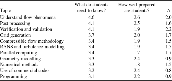
5.2 Strategies for incorporating CFD into undergraduate curriculum
The AIAA working group, which consisted of academics from a broad range of universities in the US, realised that ‘one size fits all’ was not going to be the correct answer for this problem. Every university is different, with different facilities and faculty experiences and capabilities, so the group tried to be realistic with their proposed curricular suggestions. Three basic approaches were proposed under areas labeled as: (1) CFD ‘Light’, (2) CFD ‘Moderate’, and (3) CFD ‘Heavy’. We will quickly look at each, but then also consider the implications of including CFD in aerodynamics education for textbooks.
5.2.1 CFD ‘Light’
This represents the lowest profile inclusion of CFD in an undergraduate curriculum. In such a case, an instructor of an introductory or intermediate fluid mechanics course could use pre-computed CFD simulations in order to reinforce fundamental concepts. With the availability of free high-quality visualisation software, this approach is relatively straightforward to introduce into an existing curriculum, provided a repository of solutions has already been generated. Students would be able to download the CFD solution files and use them to study fluid flow in and around various geometries. This approach would help eliminate software cost, and also introduce more realistic engineering simulations into the undergraduate curriculum while avoiding long simulation times and resources, as well as instruction needed to conduct such simulations [Reference Eldredge, Senocak, Dawson, Canino, Liou, LeBeau, Hitt, Rumpfkeil and Cummings66].
5.2.2 CFD ‘Moderate’
At this intermediate level of CFD instruction, CFD modules are used to augment course material by substituting the module into an existing lecture for a fluid mechanics or aerodynamics course, or into the accompanying lab unit of the course. The CFD content is heavier than in the CFD light scenario, in that here the students are expected to compute the solutions before analysing them. As the following examples will suggest, this approach often makes use of free or in-house inviscid aerodynamic solvers (i.e. panel and/or vortex lattice codes) in order to compute aerodynamics and predict forces on lifting surfaces [Reference Eldredge, Senocak, Dawson, Canino, Liou, LeBeau, Hitt, Rumpfkeil and Cummings66]. Examples of this approach were included in ‘A Best Practices Report on CFD Education in the Undergraduate Curriculum’ [Reference Eldredge, Senocak, Dawson, Canino, Liou, LeBeau, Hitt, Rumpfkeil and Cummings66], and include specific course modules from three universities: University of Dayton, Saint Louis University and Boise State University. These approaches rely on the use of Matlab, or freely available software such as XFOIL [Reference Drela68] or OpenVSP [69], but in some cases actual CFD software was used as well. An example of a project that could be conducted using XFOIL is shown in Fig. 30, or an OpenVSP project is shown in Fig. 31, both of which do not require extra external computer resources (just student laptops) and are freely available.
XFOIL simulation of NACA 2412 aerofoil (courtesy of Mark Drela of MIT, GNU General Public License) [Reference Drela68].

Example aircraft input geometry for OpenVSP, which is then analysed by a vortex lattice method or other applications (NASA Open Source Agreement (NOSA) version 1.3) [69].

5.2.3 CFD ‘Heavy’
The section on ‘Heavy’ inclusion of CFD had multiple examples from the US Air Force Academy, University of Dayton, Saint Louis University, University of Vermont and Boise State University, as well as possible usage examples for laboratory and aircraft design courses. The only university (at the time of publication) with a required undergraduate course in computational aerodynamics, however, was the US Air Force Academy. While the course definitely required time for students to learn about how to use a production CFD code, there were also multiple aerodynamics concepts being presented. Specifically, students learned the following aerodynamic concepts while performing their projects [Reference Cummings23, Reference Eldredge, Senocak, Dawson, Canino, Liou, LeBeau, Hitt, Rumpfkeil and Cummings66].
-
• boundary conditions and their relationship to flow type (viscous or inviscid)
-
• boundary layer thickness, growth and velocity profiles
-
• importance of understanding boundary-layer theory while doing CFD (sub-layer types and thicknesses, pressure gradients, etc.)
-
• stagnation points and stagnation streamlines
-
• flow separation and reattachment
-
• laminar separation bubbles
-
• aerofoil/wing stall
-
• aerofoil pressure gradients as a function of angle-of-attack
-
• aerofoil surface and off-surface pressures, circulation, and the resulting lift and drag variations with angle-of-attack
-
• the relationship between pressure gradients and flow separation
-
• pressure and skin friction drag
-
• unsteady vortex shedding
-
• the impact of wing-tip vortices
-
• compressibility effects at subsonic Mach numbers.
In addition, the following aerodynamic theories and concepts are taught to the students while they are performing their projects (or are learned in a prior course):
-
• NACA aerofoil designations and data
-
• potential flow theory
-
• Kutta-Joukowski theorem
-
• thin aerofoil theory
-
• lifting-line theory
So, while many faculty members might have believed they were giving up a great deal by teaching CA to their students in lieu of the more traditional syllabus, we found that many of the same concepts were still covered, but in different (and project-based) ways.
An example of the student project in our computational aerodynamics course is shown in Fig. 32. When aerofoil flowfields are computed using a Navier-Stokes solver (which is done at multiple angles of attack, including at least one post-stall angle-of-attack), the students now can see the flow (they can once again be the fluid particle rather than learn to derive the theory). They can also start to attain the outcomes of the respondents from the 1992 study conducted by Bill Mason and start to achieve ‘knowledge of flow physics’. By interrogating the boundary layer development along the chord of the aerofoil the students can see incipient flow separation and post-stall flows, as well as compare predictions of lift and drag with aerofoil data.
Flow field about an NACA 4412 aerofoil (left) and Comparison of CFD predictions with experimental data for an NACA 0012 aerofoil (right) [Reference Cummings23].

Now the students are ready to go beyond just deriving theories, but truly integrating theoretical fluid dynamics (TFD), experimental fluid dynamics (EFD) and computational fluid dynamics (CFD) approaches in project-based learning. An excellent example of integrating theory, experiments and computations is shown in Fig. 33, where the students have analysed a rectangular planform wing consisting of diamond-wedge aerofoils at supersonic speeds (in this case Mach 2.5). Experimental data was collected for the wing in the US Air Force Academy Tri-Sonic Wind Tunnel and compared with shock-expansion and Busemann’s theory for the 2D and 3D flow regions on the wing. The results are quite remarkable. Now true learning can take place, as a knowledge and ‘feel’ is developed, still based on theory, but also based on experiments and computations.
Comparison of TFD, EFD and CFD, for the 2D flow field over the diamond-wedge wing (left), and for the 3D flow field near the wing tip of the wing (right) [Reference Cummings23].

5.3 Implications for aerodynamics textbooks in the future
I think the list of topics covered in Section 5.2.3 is something that Lanchester would have wanted to see, since so many of those topics were included in Aerodynamics. The fact that this list was written over a decade ago, based on what we were doing at the US Air Force Academy with computational aerodynamics, is all the more interesting. In spite of that fact, the comparison of this list with Lanchester’s topics in Aerodynamics is quite informative, and makes me wonder if Lanchester might have seen that computational aerodynamics was helping to return aerodynamics books to his side of the ‘divide’. For example, as we began teaching computational aerodynamics to undergraduate students over twenty years ago, we realised there was no textbook appropriate for undergraduate students, so we ended up writing our own [Reference Cummings, Mason, Morton and McDaniel70]. This textbook still includes the results of aerodynamic theories (because we believe students still need to know those theories), but now takes them further into the aerodynamic triad of TFD/EFD/CFD. That will, hopefully, lead to students who are better prepared to tackle the problems associated with being an aerodynamicist (or performance or flight controls or structural engineer) in their future. Another textbook that incorporates computational simulations into an aerodynamics education is Flight Vehicle Aerodynamics by Mark Drela of MIT [Reference Drela71]. While the specific approaches are somewhat different in both books, the basic approach is similar: help students gain knowledge about aerodynamics using computational and theoretical approaches, something we hope Lanchester would have appreciated.
6.0 Concluding remarks
We have looked at the life and aerodynamic contributions of Frederick W. Lanchester from many perspectives, including his early experimentation, the resulting concepts for circulation and vortex-induced drag, as well as total aircraft resistance, and so much more. We have also evaluated multiple reasons was it was so difficult for him to publish his work, which eventually led him to write his book Aerodynamics in 1907. His contributions to aerodynamics were profound, but not recognised in a way that directly led him to influence the development of aerodynamic theory. Rather, his impact was seen to be from the design side of the divide that existed at the time between theory and practice. In spite of this, he continued to have a part to play as the number of books on aerodynamics blossomed after 1920, and his impact can be seen in the view of aerodynamics that relates to understanding flow physics more than understanding theoretical developments. As we now find ourselves in a new aerodynamic paradigm, we perhaps can start to return to Lanchester’s roots of seeing aerodynamics as a practical applied science for those who are interested in designing airplanes. His approach, as well as the reasons why he thought it was so important to write Aerodynamics, have turned out to be prophetic as we find ourselves in a time where we can re-invent aerodynamics as the culmination of theoretical, experimental and computational approaches. Lanchester stands as a person who saw the importance of that over a century ago, and we would be wise to learn from his example as we find the right path forward for the future of aerodynamics education.
Acknowledgements
A number of people have been instrumental in the development of this lecture and article. First of all, I want to thank Paul Bruce of Imperial College and the RAeS’s Aerodynamic Specialists Group for inviting me to give the Lanchester Memorial Lecture; I am greatly honored by their invitation and only hope that I have lived up to their faith in me. I also want to thank several people who were instrumental in helping me find information for the lecture, including Paul Bruce of Imperial College, Chris Atkin of the University of East Anglia, Marilyn Smith of Georgia Tech, and Mark Drela of MIT. Philip Jarrett graciously gave me access to some of his personal photograph collection and was also a willing proofreader of the article. Dave Hall and Levi Brodman were also willing proofreaders who provided wonderful feedback. Finally, I want to thank everyone responsible for putting together the collection within The Lanchester Interactive Archive supported by Coventry University. That archive is a wonderful resource of documents, images, notebooks, sketchbooks, reports, patents and much more.



