Introduction
The multiple input multiple output (MIMO) antenna system is used to increase the data rate and capacity of the system. The multiple antennas at the transmitter are used to transmit different data streams simultaneously, and results in high data rate in megabits per second and gigabits per second. The close proximity of radiators in MIMO results in mutual coupling, which degrades the actual achievable performance of compact and closely spaced antenna elements. Various methods like de-coupling structures, parasitic elements, etc., have been reported in the literature to solve the issue of mutual coupling.
The portable electronic devices have small space to mount antenna on printed boards. The two-element antenna for 2.4/5.2/5.8 GHz with high isolation was designed for ultra-thin electronic devices [Reference Chen, Sze and Chuang1]. In the MIMO system, various approaches are used to improve the mutual coupling. An annular slot approach was used to reduce the mutual coupling and provides 18 dB of isolation in the operating band [Reference Khan and Sharawi2]. A simple slot could be used to improve the isolation between antenna elements and achieved the isolation of more than 12 dB [Reference Soltani, Lotfi and Murch3]. The combination of slot etching on the ground and coupling network can be used in 2.37–2.46 GHz frequency band for isolation and impedance matching [Reference Cui, Gong, Liu, Jiang and Guan4]. The decoupled dual antenna provides wide bandwidth of 1.01 GHz with more than 15 dB of isolation [Reference Huang and Wu5]. The inverted L-slot for 2.4/5.2/5.8 GHz applications and integrated structure were used to enhance isolation in MIMO antenna [Reference Liu, Qin and Wang6, Reference Ramachandran, Mathew and Vinesh7]. Different isolation methods like complementary split ring resonator (CSRR) can be used to improve the isolation and diversity performance of antenna. The placement of CSRR on ground plane results in compactness of MIMO and also improves isolation [Reference Ramachandran, Pushpakaran and Pezholil8, Reference Malathi and Thiripurasundari9]. The resistive elements are also used to achieve the better performance of antenna for wideband application. The resistive element can be fed between the antenna elements to reduce surface current. The isolation of 17.6 dB at 2.4 GHz resonant frequency was found in this design [Reference Venkatasubramanian, Li and Lehtovuori10]. Similarly, the metamaterial mushroom-shaped structure was used between the antenna elements to provide significant improvement in the isolation at 2.4 GHz [Reference Zhai, Chen and Qing11]. A discrete mushroom shape was used for better isolation performance and achieved isolation of 35 dB [Reference Zhai, Chen and Qing12]. The MIMO performance in terms of capacity can be observed for 2.4 GHz wireless applications [Reference Mabrouk, Talbi, Nedil and Denidni13]. The ring hybrid orthogonal feeding network helps to improve the performance of antenna in terms of mutual coupling [Reference Gong, Jiao and Gong14]. The hybrid feeding structure for full duplex system achieved 35 dB of isolation and envelop correlation coefficient (ECC) of 0.001 at 2.4 GHz wireless local area network (WLAN) applications [Reference Makar, Tran and Karacolak15]. A MIMO antenna was designed for tri-band WLAN and wireless interoperability of microwave access (WiMAX) applications with L-shaped slit to achieve the isolation of 16 dB [Reference Karimian, Soleimani and Hashemi16]. An antenna using flag-shaped stub was utilized to improve the isolation among antenna elements and provides more than 18 dB of isolation [Reference Katie, Jamlos and Alqadami17]. The combination of dual feed structure using cross-coupled semi-loop and inverted F antenna combination produces >12 dB of isolation [Reference Lee and Cho18]. The input–output coupling can be tuned by tunable decoupling network, which minimizes the mutual coupling and produces more than 20 dB of isolation between antenna elements [Reference Kewei and Decheng19]. Similarly, a T-shaped resonator is placed between two antenna elements and provides more than 15 dB of isolation at ports [Reference Liu, Yang and Liu20]. The hexagonal cut in patch antenna [Reference Chouhan, Gupta and Panda21], ground modification technique [Reference Malviya, Panigrahi and Kartikeyan22], defected ground plane [Reference Chouhan, Gupta and Panda23], and pattern diversity [Reference Malviya, Panigrahi and Kartikeyan24] are also used to improve the isolation and contribute in compactness of the overall size. In the past few years, lots of MIMO antennas have been designed for S-band application and human interfaces devices. The effect of human body on the MIMO antenna parameters in near-field region was discussed and analyzed [Reference Joo, Kwon and Choi25]. The various antennas [Reference Paul, Mridula, Aanandan and Mohanan26–Reference Zhang and Brown29] were designed with octagonal-shaped geometry, which covers wideband and UWB applications with isolation of at least −10 dB. The coupling response for various shapes was also presented, and octagonal shape was compared with circle and square shapes. Various shapes such as square, circular, elliptical, pentagonal, hexagonal, and octagonal, etc., are analyzed, and out of these, the octagonal shape is considered for proposed design. The presented design in paper covers S-band and human interface device (HID) applications simultaneously with octagonal ring approach. The problem of radiation effect on human body is also considered.
In this paper, a four-element octagonal ring-shaped MIMO antenna for HID (Bluetooth/wireless/Wi-Fi interface) and S-band application is designed and analyzed. The antenna covers the frequency band of 2.1–4.0 GHz. The proposed MIMO antenna uses the combination of octagonal ring-shaped radiating structure and isolation structure. With the help of proposed modified feeding method and isolation structure on ground plane, bandwidth of 1900 MHz is achieved with improved isolation. An additional parasitic element is placed on ground plane to increase the isolation between ports. The specific absorption rate (SAR) performance of MIMO antenna is evaluated for HID. The main challenge of any HIDs is the SAR performance near the human body. The most sensitive part of our body is the head. This SAR performance of proposed MIMO antenna gives considerable SAR near the human head and ear. The design structure results in less SAR as well as covers wide range of applications including S-band.
Design studies
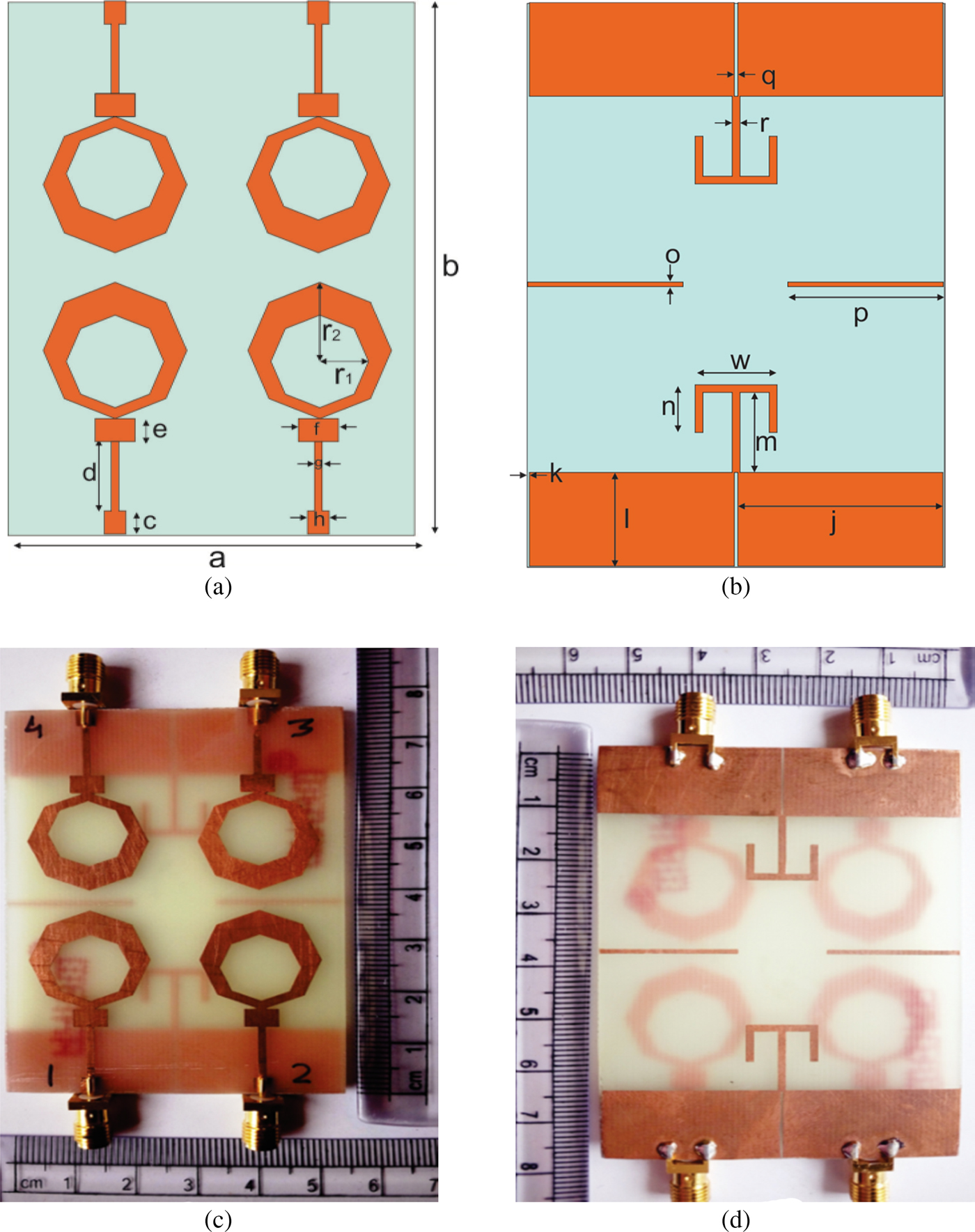
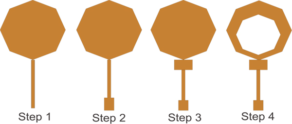
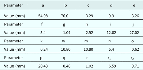
The layout and prototype of the proposed MIMO antenna are shown in Fig. 1. The optimized dimensions of the antenna geometry are listed in Table 1. It is fabricated on FR4 dielectric substrate, which has relative permittivity of 4.4 and loss tangent of 0.02. The area of the substrate is 54.98 mm × 76 mm. The four octagonal ring-shaped radiators are printed on the top layer of substrate. On the bottom layer, a T-shaped isolation element and a parasitic element are printed to control the effects of mutual coupling among MIMO antenna elements. A partial ground is utilized in the design to reduce the overall size of the MIMO antenna structure. The antenna geometry is described in four steps as shown in Fig. 2. Initially, a microstrip line fed octagonal monopole antenna with a radius of 9.71 mm was designed by using standard design equations [Reference Singhal, Singh and Singh30]. Thereafter, the conventional feed line is replaced with a modified feed line comprising three sub-sections having impedance of the order of 50, 70, and 35 Ω to achieve better impedance matching, resulting into improved return loss. Since the current is concentrated along the periphery of radiator, it is loaded with a central octagonal slot of radius 6.59 mm without affecting the antenna performance significantly. The octagonal ring also enhances the bandwidth of MIMO antenna. In case of MIMO antenna configuration, two antenna elements are placed in spatial diversity configuration and the resulting configuration is mirrored along the y-axis to design the final antenna geometry. To decouple the antenna elements, T-shaped elements are loaded on the ground plane and the rectangular parasitic elements are introduced. The T-shaped structure here connects both the separated grounds and shifts the higher frequency toward lower side, which makes the design practically suitable for HIDs. The octagonal ring shape is chosen because it occupies less metalized area on substrate as compared with existing configurations and shows less coupling. The slot on the octagonal patch creates octagonal ring which produces wider bandwidth response.
Schematic views and fabricated views of the proposed MIMO antenna: (a) schematic front, (b) schematic back, (c) fabricated front, (d) fabricated back.

Design steps of the proposed antenna structure.

Optimized values of considered parameters (mm)

Results and discussion
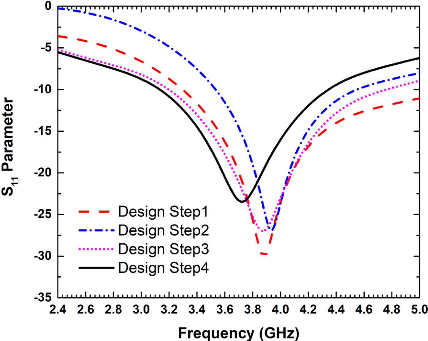
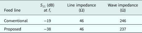
The comparison of proposed structure with modified feed line and conventional feed line is listed in Table 2. The design steps return loss results are shown in Fig. 3 with partial ground. The results of design steps 1, 2, and 3 show the frequency bands of 3.3–5.5, 3.5–4.5, and 3.2–4.7 GHz, respectively. The design step 4 has a frequency band of 3.1–4.3 GHz. The design step 4 after adding parasitic element and T-shaped structure shifts the frequency to the lower side and results in enhancement of isolation. The results of design step 4 with parasitic element and T-shaped structure are given in Fig. 4.
S 11 parameter of the design steps.

S parameters of the proposed MIMO.

Comparison of conventional and modified feed line

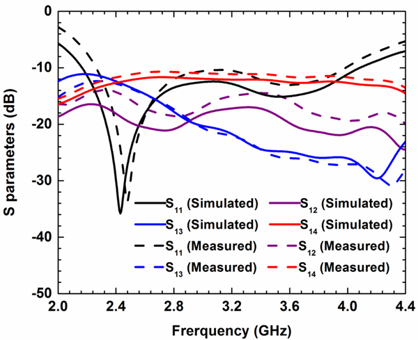
The computer simulation tool (CST)-simulated and vector network analyzer (VNA)-measured scattering parameters of the proposed MIMO antenna are presented in Fig. 4. After design and fabrication of the proposed antenna, the next step is to evaluate the performance of antenna by measuring and testing. The open boundary condition and electric shielding at 50 Ω port have been considered to obtain the results. Initially, VNA is calibrated by calibration kit and then results are measured when port 1 is excited and remaining ports are terminated with 50 Ω. There are three vector receivers inside the VNA and each can measure amplitude and phase simultaneously. The simulated and experimental −10 dB S 11 frequency bands of the proposed antenna are 2.1–4.0 and 2.27–3.9 GHz, respectively. The simulated and measured resonant frequencies of the proposed antenna are 2.43 and 2.47 GHz. The small variations in measured results are due to fabrication errors. The isolation S 12, S 13, and S 14 are the port isolations between pair of ports 1–2, 1–3, and 1–4. The values of S 12, S 13, and S 14 in the simulated frequency band are 16, 11, and 12.5 dB. Similarly, the measured values of S 12, S 13, and S 14 are 14, 12.33, and 11.29 dB.
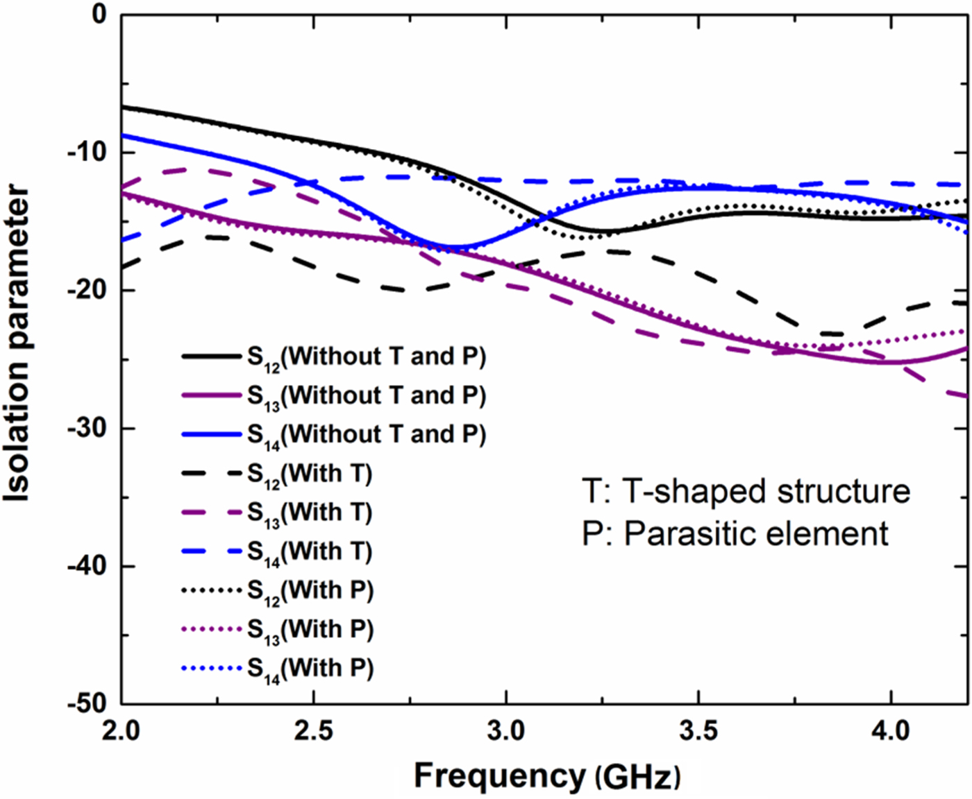
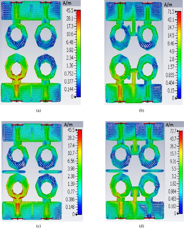
To control the effect of mutual coupling, surface current is analyzed at 2.4 GHz resonant frequency. When port 1 is excited, the coupling due to surface wave occurs and current flowing on the surface has a great impact on S 12, S 13, and S 14. The results of isolation parameters for different cases are shown in Fig. 5. In the absence of T-shaped isolator and parasitic element, the isolations between ports 1–2, 1–3, and 1–4 are 8.8, 15.5, and 11.63 dB at a resonant frequency 2.4 GHz. The surface current distribution without T-shaped and without parasitic element is shown in Fig. 6(a). The surface current distribution with T-shaped element is shown in Fig. 6(b). In the presence of T-shaped isolator, the isolations between ports 1–2, 1–3, and 1–4 are 17.2, 11.7, and 11.64 dB. The T-shaped isolation structure is placed in ground plane to reduce the value of surface current due to the direct current linking of ports 1–2 and 3–4. The isolation between ports 1–4 and 2–3 can also be maintained by the placement of parasitic element between these ports as shown in Fig. 6(c). In the presence of parasitic element, the isolations between ports 1–2, 1–3, and 1–4 are 8.9, 15.7, and 11.64 dB. When both the T-shaped isolator and parasitic element are included in the design, the wide-band characteristic is observed as shown in Fig. 4. When other ports are excited, the same effect can be seen due to the same type of radiating element. The significant improvement can be seen in adjacent port 1–2, a small improvement in opposite port 1–4, and small degradation in diagonal port 1–3 and is observed due to proposed isolation structures.
Isolation parameter for different cases.

Current distribution (a) without T-shaped isolator and parasitic element, (b) with T-shaped isolator, (c) with parasitic element, (d) with parasitic element and T-shaped isolator.

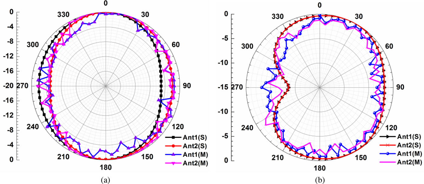
The far-field characterization of the proposed design has been carried out for E and H-field radiation patterns. The antenna was mounted in horizontal and vertical manner in an anechoic chamber to measure the E/H-field results with the help of positioning software. Since all the elements are identical, the simulated radiation pattern of one excited port and other ports terminated with matched loads are validated in an anechoic chamber at 2.4 GHz resonant frequency. The simulated and experimental patterns are shown in Fig. 7. The near to omni-directional patterns are observed in E-plane. The main lobe magnitudes, main lobe directions, and 3 dB angular widths of E-plane are 15.7 dBV/m, 355°, and 272.9°, respectively. Similarly, the H-plane main lobe magnitudes, directions, and 3 dB widths are 35.5 dBA/m, 26° and 287.6°, respectively.
Field patterns of the proposed antenna: (a) E-field, (b) H-field (S, simulated; M, measured).

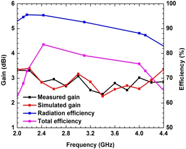
The simulated far-field antenna gain taken from CST is measured in an anechoic chamber and it varies from 2.3 to 3.3 dBi in both the simulated and measured frequency bands. The standard horn antenna was chosen as a reference antenna to measure the gain. The measured MIMO antenna gain is 2.83 dBi at 2.4 GHz resonant frequency. Figure 8 shows the variations of gain and efficiencies with the frequency for the proposed MIMO antenna. The radiation or antenna efficiency is the ratio of radiated power to input power, whereas the total efficiency is the product of antenna efficiency and mismatch loss which is evaluated by CST simulation tool. The simulated radiation efficiency ranges between 87 and 95%. The radiation efficiency at 2.4 GHz resonant frequency is 95%. The total efficiency in the whole simulated frequency band (2.1–4.0 GHz) is varied from 68 to 84%.
Gain and efficiency.

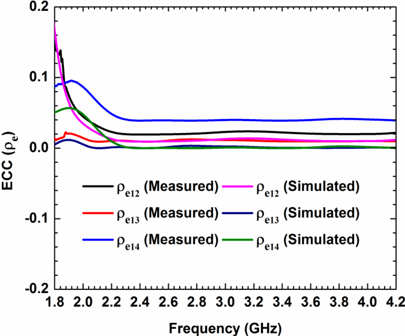
The simulated and measured ECC results are shown in Fig. 9. The simulated result of ECC is <0.02 in the whole simulated frequency band, and indicates the good diversity performance of MIMO. The international telecommunication union has a set limit of 0.5. To achieve the good diversity performance, ECC must be <0.5. Here the value of 0.02 shows very small correlation among the antenna elements. The MIMO antenna parameter ECC is used to find the diversity characteristic of the MIMO antennas, which can be determined from the mutual coupling and return loss at the ports, and is given in equation (1) and (2) [Reference Chouhan, Panda, Gupta and Singhal31].
 $$\vert {\rho_e\lpar {i,j,N} \rpar } \vert = \displaystyle{{\left \vert {\mathop \sum \nolimits_{n = 1}^N S_{i,n}^{^\ast} S_{n,j}} \right \vert} \over {\sqrt {\left \vert {\mathop \prod \nolimits_{k\lpar { = i,j} \rpar } \left[ {1-\mathop \sum \nolimits_{n = 1}^N S_{i,n}^{^\ast} S_{n,k}} \right]} \right \vert}}}, $$
where i, j are the antenna elements and N is the number of antennas.
ECC simulated and measured.

For the two-element antenna system, ECC can be given as:
 $$\rho _{12} = \displaystyle{{\vert {{ {S_{11}^{^\ast} S_{12} + S_{21}^{^\ast} S_{22}} \vert }^2} } \over {\lpar {1-{\vert { {S_{11}} \vert } }^2-{\vert { {S_{21}} \vert } }^2} \rpar \lpar {1-{\vert { {S_{22}} \vert } }^2-{\vert { {S_{12}} \vert } }^2} \rpar }},$$
where S 11, S 22 are return losses at two ports and S 21, and S 12 are the isolation parameters.
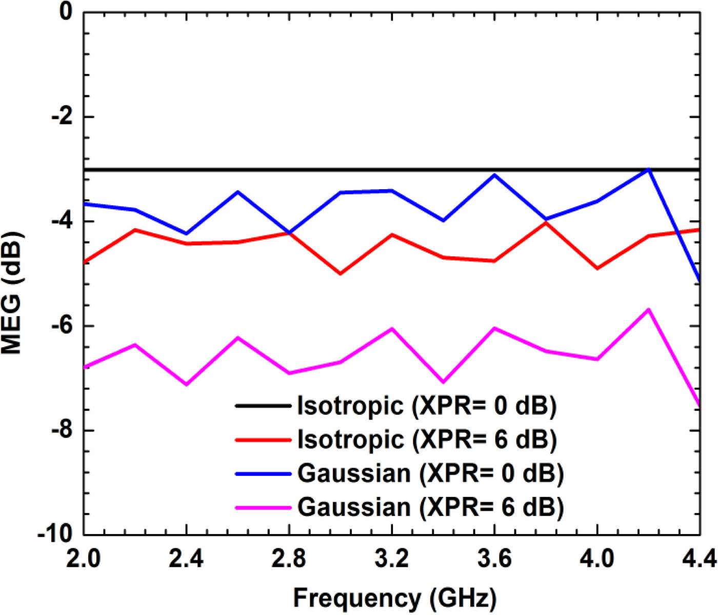
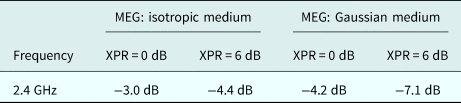
The MEG is the antenna performance parameter, which is a ratio of the mean received power to the mean incident power of the MIMO antenna element. The MEG can be used to estimate the average received signal strength of each antenna, which can be calculated by (3) [Reference Chouhan, Panda, Gupta and Singhal31]. The MEG is calculated for isotropic and Gaussian/uniform mediums to analyze the diversity performance, for different values of cross-polarization ratio (XPR) using CST simulations. The MEG for isotropic medium with XPR = 0 dB is −3.0 dB, and is constant for the presented band. The MEG lies in the range of −4.0 to −4.9 dB for XPR = 6 dB. Similarly, the values of MEG for Gaussian medium with XPR = 0 dB and XPR = 6 dB lie in the range of −3.1 to −4.2 dB, and −6.0 to −7.1 dB, respectively. Figure 10 shows all the values of MEGs for isotropic and Gaussian mediums for the presented band. Comparisons of different values of MEGs are given in Table 3 at 2.4 GHz resonant frequency.
 $$\eqalign{MEG_i & = \displaystyle{{P_{rec}} \over {P_{inc}}} = {\islant 10%\oint} \left[ {\displaystyle{{XPR.G_{\theta i}({\rm \Omega} ) + \; G_{\phi i}({\rm \Omega} ).P_\phi ({\rm \Omega} )} \over {1 + XPR}}} \right]d{\rm \Omega} \cr & = \int_0^{2\pi} \int_0^\pi \left( {\displaystyle{{XPR} \over {1 + XPR}}G_\theta \lpar {\theta, {\islant 20%\emptyset}}\, \rpar P_0\lpar {\theta, {\islant 20%\emptyset}} \,\rpar } \right. \cr & \quad \quad \quad \left. + \displaystyle{1 \over {1 + XPR}}G_\emptyset \lpar {\theta, {\islant 20%\emptyset}} \rpar P_\emptyset \lpar {\theta, {\islant 20%\emptyset}}\, \rpar \right){\rm sin}\theta d\theta d{\islant 20%\emptyset},} $$
where pθ and pϕ are the angular density functions of incident.
Mean effective gain.

Simulated MEG comparison of proposed 2 × 2 MIMO antenna at resonant

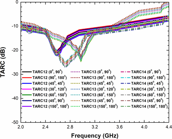
The MIMO antenna with the arbitrary signals and their excitation angles are incorporated in the frequency response and can be obtained in terms of total active reflection coefficient (TARC). Figure 11 shows the TARC curves for the proposed MIMO antenna with combinations of different excitation angles. The bandwidth of an MIMO antenna is accurately characterized by TARC rather than scattering matrix. TARC contains the effect of mutual coupling and the phase of incident wave. TARC can also be defined as the return loss of the whole MIMO antenna. TARC bandwidths of 1.2 GHz are observed with best combination of excitation angles of 150°, 180°.
Proposed MIMO antenna TARC.

TARC can be calculated by equation (4) [Reference Malviya, Panigrahi and Kartikeyan32].
 $${\rm \Gamma} _a^t = \displaystyle{{\sqrt {{\vert {S_{ii} + S_{ij}{^\ast}e^{\,j\theta}} \vert } ^2 + {\vert {S_{\,ji} + S_{\,jj}{^\ast}e^{\,j\theta}} \vert } ^2}} \over {\sqrt N}}, $$
where i and j are the element of antenna, θ is the phase angle, and N is the number of antenna.
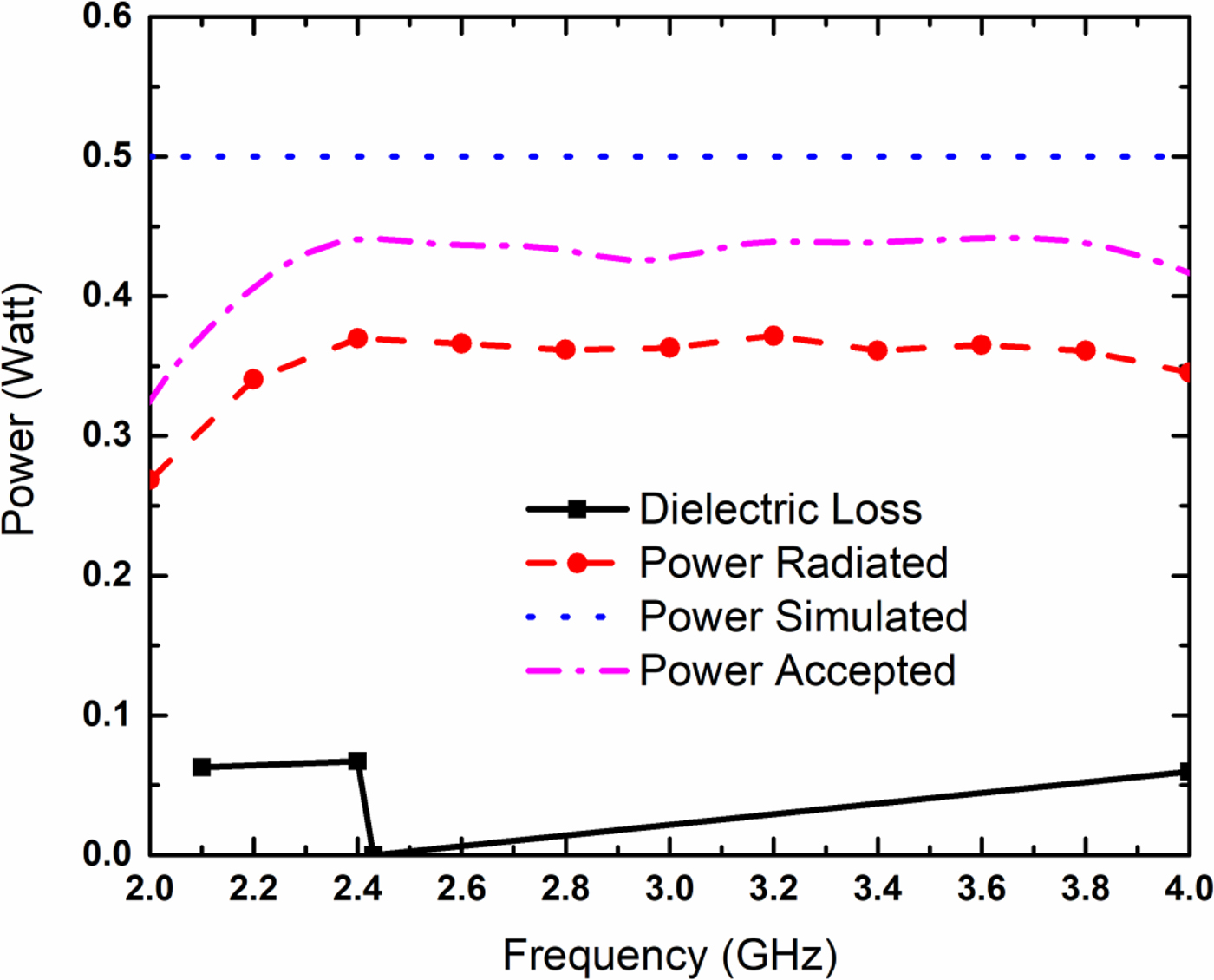
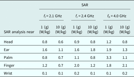
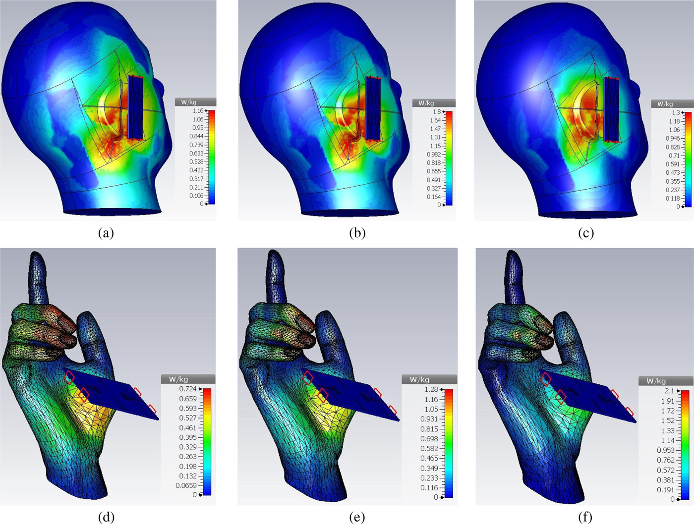
The designed antenna covers HID applications. The HIDs such as Bluetooth headset, earpiece, wireless mouse, and keyboard are generally used near the human head, ear, and hand. Sometimes the radiation from antenna is absorbed by the human body. The radiation from the RF devices/HIDs in human body is measured by the parameter SAR. The IEEE C95.1.1999 is given the SAR limit of 1.6 W/kg in averaging 1 g mass, while ICNIRP is given 2 W/kg in a 10 g averaging mass. The proposed MIMO antenna covers 2.1–4.0 GHz frequency band, so that Table 4 shows the comparison of the SAR at lower frequency (f l = 2.1 GHz), resonant frequency (f r = 2.4 GHz), and upper frequency (f h = 4.0 GHz). The SAR is compared near the human head, ear, palm, fingers, and wrist over 1 g of tissue and 10 g of tissue both. Figure 12 shows the radiated power, dielectric losses, simulated power, and power accepted for SAR calculations.
Proposed MIMO antenna power versus frequency plot.

SAR near body parts at lower, upper, and resonant frequencies

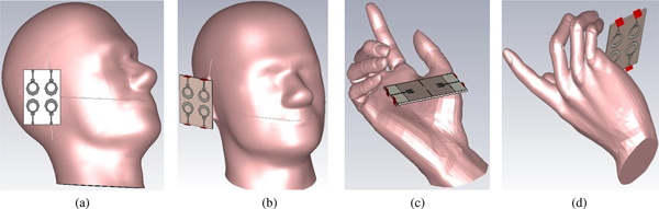
Figures 13 and 14 show the proposed antenna position and SAR near the human body parts. The obtained results show the SAR values of CST-simulated antenna are below the safety limit. The SAR of any RF electronics device is obtained by measuring the electric field in the simulated human tissue in close proximity to the device, and is calculated by equation (5) [Reference Chan, Leung, Fung and Siu33],
 $$SAR = \displaystyle{{\sigma E_i^2} \over \rho}, $$
where E i is the rms value of the electric field strength in V/m, σ is the conductivity of body tissue in S/m, and ρ is the density of body tissue in kg/m3.
Proposed antenna: (a) human head front, (b) head prospective view, (c) antenna near palm, (d) prospective view.

SAR calculations near human head and palm: (a) SAR at 2.1 GHz, (b) SAR at 2.4 GHz, (c) SAR at 4.0 GHz, (d) SAR (palm) at 2.1 GHz, (e) SAR (palm) at 2.4 GHz, (f) SAR (palm) at 4.0 GHz.

The SAR is ≤1.2 W/kg near human head, which is acceptable as per the standard [34]. The SAR results are considered using human head model and the material chosen for simulation is bio tissue/skin where the density, thermal conductivity, heat capacity, diffusivity, blood flow, and metabolic rate are 1100 kg/m3, 0.293 W/K/m, 3.5 kJ/K/kg, 7.61039e−008 m2/s, 9100 W/K/m3, and 1620 W/m3, respectively. The IEEE/ICE 62704-1 averaging method has been chosen for SAR calculation, which is widely used. Here the SAR performance of antenna is evaluated without using any plastic jacket/cover, thus by putting antenna inside a cover/jacket and by placing some far from ear, the SAR performance can be increased more.
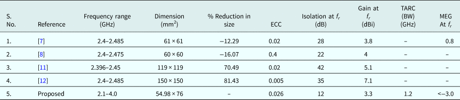
The comparison of the previously reported work with the proposed work is given in Table 5. In the table, compact MIMO antenna [Reference Ramachandran, Mathew and Vinesh7, Reference Ramachandran, Pushpakaran and Pezholil8] has a bandwidth of only 85/75 MHz, and unable to accommodate 2.5/3.5 GHz WiMAX bands. Remaining references have wide antenna dimensions. The proposed design is capable in accommodating all the WLAN/WiMAX bands and S-band coming under the range of 2.1–4.0 GHz frequency, and has a good performance in the proposed frequency band. The isolation ≥10 dB for 2:1 VSWR band is sufficient for HIDs and S-band application.
Comparison of proposed MIMO (2 × 2) with previous work

Conclusion
A four-element compact MIMO antenna for 2.1–4.0 GHz frequency band has been proposed. The antenna resonates at 2.4 GHz frequency and provides more than 11 dB of isolation in whole frequency band. The proposed MIMO with octagonal ring structure has a bandwidth of 63% and a TARC bandwidth of 1.2 GHz. The ECC is <0.026 in the frequency band and MEG of the proposed antenna is <−3.0 dB. The gain of MIMO antenna is 2.83 dBi, and the radiation efficiency ranges between 87 and 95%. The SAR results are evaluated near the human head, ear, hand, palm, and wrist and are found satisfactory. The designed MIMO antenna structure with the wide-band fulfils the requirement of the modern MIMO wireless devices.
 Sanjay Chouhan received his B.E. degree in Electronics Engineering, from the Jawaharlal Institute of Technology, Borawan-Khargone (MP), India, in 2003, M.E. degree in Electronics and Telecommunication, from Shri G. S. Institute of Technology and Science, Indore (MP), India, in 2008. Currently he is pursuing Ph.D. from Amity University Gwalior, India. His area of interest is MIMO antenna design for wireless applications. He also won the best paper award in the National Conference at Amity University Gwalior. He is a Life Member of the Indian Society for Technical Education (ISTE). He published over 30 research papers in journals and conference.
 Debendra Kumar Panda was born in Orissa, in 1970. He graduated in Chemistry from Utkal University in year 1992 and became an Associated Member of IETE in 1997. He did his M.E. in Digital System and Instrumentation from BEC (DU), Howrah, West Bengal, India, in the year 2003. He obtained his Ph.D. from IIT Kharagpur, India, in 2010. He worked as a Lecturer in the Department of Electronics and Communication Engineering of JIS college of Engineering, Kalyani, India, in 2003. He joined College of Engineering and Management, Kolaghat, India, as a Lecturer in the year 2005. Currently he is working as Dean, Faculty of Engineering at Medicaps University, Indore, India. His research interests are numerical techniques in electromagnetics, waveguide power dividers/combiners and waveguide slot antennas, microstrip antennas, beam-forming techniques, and low-power VLSI circuits.
 Vivek Singh Kushwah received his B.E. degree from the Institute of Technology and Management, Rajiv Gandhi Technical University, India, in 2005, M.Tech. degree from Madhav Institute of Technology and Science, Rajiv Gandhi Technical University, India, in 2007, and Ph.D. degree in Electronics Engineering from Madhav Institute of Technology and Science, Rajiv Gandhi Technical University, India, in 2016, respectively. He is now working as an Assistant Professor and Research Coordinator in the Electronics and Communication Engineering Department, Amity School of Engineering and Technology, Amity University Gwalior, MP, India, since 2011. He has more than 12 years of teaching experience in academics. His areas of interests include artificial neural networks, microstrip antenna, RF, and microwave filters. He published international book chapters and more than 50 research papers in various reputed international and national journals and conferences throughout the world.
 Pankaj Kumar Mishra is currently working as an Associate Professor, Applied Physics, Amity School of Engineering and Technology, Amity University Madhya Pradesh, Gwalior, India. Dr. Mishra has a teaching and research experience of almost 17 years. For his meritorious performance, he was conferred with Gold medal in postgraduation. He completed his research project titled “study of performance of electrets based on novel polymer blends” funded by MP Council of Science and Technology, Bhopal, India, and coauthored a book on Applied Physics (Theory and Experiments), published by University Science Press (an imprint of Laxmi Publications Ltd.). He published 50 research papers in international/national journals of repute in the field of microelectronics.