

Introduction
There is a wealth of information in the literature regarding cholesterol granulomas of the petrous apex, along with much discussion regarding management of this rare lesion. Conventionally, access to the petrous apex has been gained via an infracochlear or a middle fossa approach.Reference Brackmann and Toh1 However, recent advancements in endoscopic sinus surgery have enabled less invasive surgical intervention with fewer associated morbidities.
We present a complex case that required multistage surgical intervention on account of the unusual peri- and post-operative complications that arose. Such a case has not previously been described in the literature.
Case report
A 52-year-old woman with a 6-month history of diplopia presented to ophthalmologists with left-sided abducens nerve palsy. She had no other neurological symptoms and hearing function was normal. Initial radiological work-up in the form of computed tomography (CT) confirmed the presence of an expansile and erosive lesion of the left petrous apex, lying intimately and posterolaterally to the internal carotid artery (ICA). The patient was subsequently referred to the otolaryngology department at Charing Cross Hospital, London.
The case was discussed with the regional skull base multidisciplinary team (MDT). A lateral surgical approach was deemed unsafe based on the position of the cholesterol granuloma in relation to the ICA. In light of this, and the fact that the patient's hearing thresholds were normal, a transnasal approach was considered to be the best option.
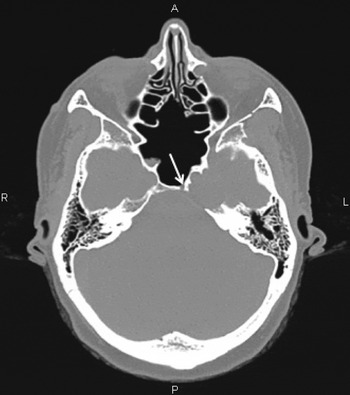
The left petrous apex was approached using a standard endonasal transsphenoidal technique with an image guidance system (BrainLab, AG, Heimstetten, Germany). The anterior wall of the sphenoid sinus and intersinus septum were removed, and both the left ICA and optic nerve were identified. The petrous bone was drilled medial to the carotid artery. On advancing towards the lesion, the ICA was unexpectedly observed to be in much closer vicinity than anticipated from initial imaging. We decided at this stage that a transnasal approach was potentially dangerous because of the risk of damage to the ICA. The procedure was therefore stopped, leaving a small drainage ostium on the wall of the lesion (Figure 1).
Axial computed tomography image demonstrating an erosive lesion of the left petrous apex. Note the widely opened sphenoid sinus and small drainage ostium (arrow) medial to the carotid artery. R = right; A = anterior; P = posterior; L = left

There was no symptom resolution at the six-week follow up. We adopted active monitoring and the patient was reviewed regularly.
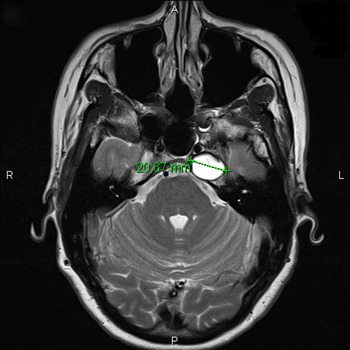
The patient presented with worsening diplopia 20 weeks post-operatively; she was otherwise fit and well, with no additional neurological deficits. Repeat CT demonstrated new bony dehiscence of the posterior petrous ridge and posterior wall of the horizontal carotid canal. Magnetic resonance imaging (MRI) with gadolinium-based contrast demonstrated a well-defined, hyperintense lesion on T2-weighted images. The lesion was intimately related to the left ICA, which was displaced anteromedially, with an effaced Meckel's cave (Figure 2).
Axial, T2-weighted magnetic resonance image of petrous bones, showing a well-defined lesion measuring 20.67 mm in diameter. Note the left internal carotid artery directly anterior to the lesion. R = right; A = anterior; P = posterior; L = left

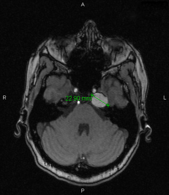
The case was re-discussed with the skull base MDT, where again the transnasal approach was considered the safest option in terms of manipulating and mobilising the ICA to access the cholesterol granuloma. As there was a significant risk to the ICA, a carotid occlusion test was performed in conjunction with the neuroradiology department to test collateral circulation. The left cervical ICA was successfully occluded for 12 minutes with no neurological deficits. Magnetic resonance angiography was also performed to ascertain the position and path of the ICA, and surrounding neurovascular structures, in relation to the granuloma. This incidentally revealed that the lesion had significantly increased in size since initial imaging, causing further bony dehiscence of the carotid canal (Figure 3).
Axial, T1-weighted magnetic resonance image demonstrating the lesion measuring 22.90 mm in diameter. Its anteromedial surface has eroded through the bone of the carotid canal. Large posterior septal defect and loss of ethmoid septal architecture posteriorly (from previous surgery) can be seen. R = right; A = anterior; P = posterior; L = left

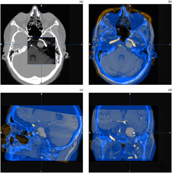
Further CT and MRI scans were obtained; these were fused using image guidance software (iPlan Cranial 3.0, BrainLab) to facilitate pre-operative planning and intra-operative accuracy (Figure 4).
Axial (a) & (b), sagittal (c), and coronal (d) magnetic resonance and computed tomography BrainLab fusion images. R = right; A = anterior; P = posterior; L = left; S = superior; I = inferior

With neurosurgical and radiological colleagues on standby, the lesion was re-approached using the same left-sided, endonasal transsphenoidal technique with image guidance. The left middle turbinate was excised for access and the sphenopalatine artery was cauterised. A 2.5 mm diamond burr drill (Medtronics Xomed, Jacksonville, Florida, USA) was used to advance inferomedially along the vidian canal to the second genu of the ICA. The second genu of the ICA and paraclival carotid were skeletonised using a 3.0 mm diamond burr drill (Medtronics Xomed). Drilling was continued into the clivus to expose the cholesterol granuloma. At this juncture, uncontrollable bleeding was encountered from the clival venous plexus. More than one litre of blood was lost despite all attempts to control the haemorrhage (using diathermy and haemostatic agents), rendering it unsafe to continue the surgery. The procedure was halted with Surgicel (an absorbable haemostatic agent) (Ethicon, Somerville, New Jersey, USA) and Whitehead's varnish packs following a transfusion of two units of blood.
With the packs remaining in situ, the patient was commenced on antibiotics (clarithromycin). Post-operative CT showed a small pneumocephalus in the region of the tuberculum sella, although the patient had no neurological symptoms. The patient was closely observed for 72 hours (as per neurosurgical advice) and subsequently discharged.
Six days post-operatively, the patient presented with severe headaches and nausea. Subsequent imaging showed significant pneumocephalus anterior to the frontal lobes. With neurosurgical advice, this was managed conservatively until scheduled pack removal one week later.
At surgery, the packs were safely removed and the operation field was found to be dry. The residual bone over the ICA and the cholesterol granuloma were removed with a standard neurosurgical drill (Medtronics Xomed). The lesion was aspirated with a spinal needle, revealing green liquid contents which were later confirmed as cholesterol granuloma. All contents were cleared and a wide ostium was created to prevent recurrence. The inevitable cerebrospinal fluid (CSF) leak was closed with fascia lata, Tisseel glue (Baxter, Deerfield, Illinois, USA), Gelfoam Plus (Baxter) and Nasopore light packing (Polyganics, Groningen, Netherlands). In order to avoid occluding the newly formed ostium, a decision was made not to use fat or to pack the sphenoid sinus.
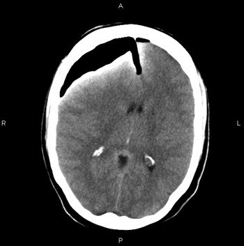
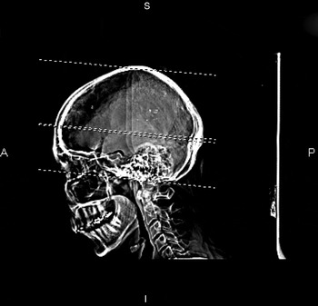
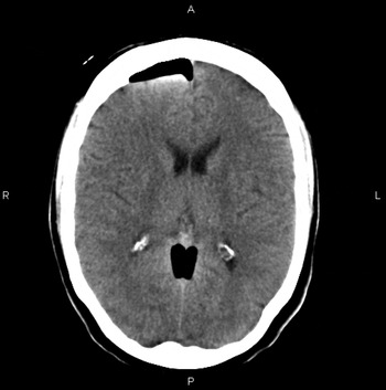
Three days post drainage, the patient complained of more severe headaches and unilateral leg weakness. She also had nystagmus, severe diplopia and Horner's syndrome. In addition, the patient experienced rhinorrhoea which tested positive for beta-2 transferrin, confirming a CSF leak. This was managed conservatively and stopped after a few days. Imaging showed an increase in the pneumocephalus, causing a new midline shift 9 mm to the left with global sulcal effacement, confirming tension pneumocephalus (Figures 5 and 6). The patient was managed conservatively with 100 per cent oxygen, and nursed in the supine position. The pneumocephalus gradually resolved, with a reduction of symptoms (Figure 7). On discharge, the patient completed a 30-day course of antibiotics (clarithromycin).
Axial computed tomography image showing large amount of intracranial gas over right frontal lobe. Scan also shows air within the anterior cervical spinal canal, pituitary fossa, superiorly within the falx, and overlying the right temporal and left frontal lobes. No cerebellar tonsillar herniation was noted. R = right; A = anterior; P = posterior; L = left

Sagittal computed tomography image demonstrating extensive pneumocephalus. A = anterior; S = superior; I = inferior; P = posterior

Axial computed tomography image at approximately same anatomical position as Figure 5, showing further resorption of intracranial gas. Image shows significant improvement; convexity sulci and ventricles are conspicuous, with almost complete resolution of midline shift. R = right; A = anterior; P = posterior; L = left

At the one and four-month follow-up visits, the patient remained well, with no neurological symptoms or CSF leak. There was slight improvement in her left lateral rectus palsy and diplopia. At the six-month follow up, the patient was able to fully abduct her eye, well beyond the primary position, indicating considerable improvement. No ophthalmic treatment was indicated.
Discussion
Cholesterol granulomas are expansile, round or ovoid cysts. They comprise cholesterol crystals surrounded by foreign body giant cells and chronic inflammation, all contained within a thick fibrous capsule.Reference Jackler and Cho2 Cholesterol granulomas are the commonest lesions of the petrous apex, with an estimated incidence rate of 0.6 per million.Reference Lo, Solti-Bohman, Brackmann and Gruskin3
The pathogenesis of cholesterol granulomas has been much debated, but the classic ‘Obstruction-Vacuum’ hypothesis is the most widely accepted. According to this theory, large pneumatised portions of the petrous apex become obstructed due to mucosal swelling, thus blocking the circuitous pneumatic pathways to the apical air cells. This results in negative pressure, causing haemorrhage. Subsequent catabolism of haemoglobin leads to the formation of cholesterol crystals, which provoke a foreign body response resulting in ongoing granuloma formation.Reference Mosnier, Cyna-Gorse, Grayeli, Fraysse, Martin and Robier4 An interesting, more recent ‘Exposed Marrow’ hypothesis has been proposed by colleagues in San Francisco.Reference Jackler and Cho2 The authors identify various flaws in the classic hypothesis and propose that sustained haemorrhage from exposed marrow elements form the catalyst for the progressing cyst expansion. However, this theory has yet to be universally recognised.
Patients harbouring these rare lesions may not present with clinical symptoms until adjacent neurological or vascular structures are compromised.Reference Jaberoo, Hassan, Pulido and Saleh5 The largest study to date of petrous apex cholesterol granulomas found that the commonest clinical symptom was headache, followed by imbalance and diplopia.Reference Palpuzzi, Gardner, Fernandez-Miranda, Pinheiro-Neto, Scopel and Koutourousiou6 Cholesterol granulomas can be classified as aggressive or non-aggressive, and their management depends upon the location and characteristics of the lesion in question.
Non-aggressive lesions are asymptomatic and are often incidentally revealed on radiological imaging. Management usually entails active monitoring with serial imaging. The aggressive types are more common and may demonstrate clinical patterns based on the involvement of adjacent structures. Broadly speaking, there are three distinct types of aggressive cholesterol granulomas. In the first type, sensorineural hearing loss and tinnitus are the commonest presenting symptoms, followed by vertigo and dizziness. In such cases, involvement of the vestibulocochlear nerve is typical. The second type is related to a cholesterol granuloma located in the superior part of the petrous apex, in which compressional symptoms such as headache and facial pain are the principal features; this type is related to middle and posterior fossa dural irritation. In the third type, as in our patient, there is involvement of either the trigeminal or the abducens nerve, signifying compression of the Meckel's cave region. Rarely, recurrent otitis media can be a feature, indicating pressure on the eustachian tube. Surgery is considered when there are evolving neurological symptoms or signs.Reference Mosnier, Cyna-Gorse, Grayeli, Fraysse, Martin and Robier4
• Cholesterol granulomas are rare lesions occasionally found in the petrous apex
• They can present with cranial nerve palsy, or be an incidental finding on radiological imaging
• Surgical intervention should only be considered when there are evolving neurological features
• The safest route to the petrous apex is a transsphenoidal approach
• Such lesions, which are comparatively anatomically inaccessible, should only be approached with navigational aid
• Due to anatomical variance, magnetic resonance venography is recommended to avoid venous plexus bleeding
Both anatomical position and relative hearing function are important factors when considering the surgical approach. A lateral labyrinthine approach may provide easier access and better surgical exposure to some parts of the temporal bone, whereas a transnasal approach is advocated for other areas. Recent advancements in endoscopic surgery now mean that lateral approaches to the petrous apex can be avoided. The significant risks associated with lateral approaches include damage to the facial or vestibulocochlear nerve, which can result in facial weakness, hearing loss and vertigo. There is also the risk of damage to the temporal lobe, which may result in long-term seizures. In patients with relatively preserved hearing, the infralabyrinthine or infracochlear approaches might be more suitable alternatives in cases where a transnasal approach is anatomically impractical.Reference Scopel, Fernandez-Miranda, Pinheiro-Neto, Peris-Celda, Palpuzzi and Gardner7
Combined CT and MRI are essential in the management of petrous apex lesions. On CT, cholesterol granulomas appear as well-defined, erosive and cystic lesions; CT is therefore an important tool to assess the extent of bony erosion. Magnetic resonance imaging is also valuable as it can demonstrate high-signal intensity on both T1- and T2-weighted images.Reference Presutti, Villari and Marchioni8 Combined scanning is paramount when planning a minimally invasive approach for surgical intervention. In the case reported here, the MRI and CT images were fused pre-operatively (using image-guidance software) to improve intra-operative accuracy.
Conclusion
With recent advancements in endoscopic sinus surgery and the use of image-guided navigation systems, the transnasal approach to the petrous pyramid has become the favoured method as it is considered much less invasive.Reference Chatrath, Nouraei, De Cordova, Patel and Saleh9 The safest approach to the petrous apex would be a transsphenoidal approach. In light of anatomical variance, magnetic resonance venography is recommended to avoid venous plexus bleeding. As demonstrated by our patient, who encountered several complications, a transsphenoid approach to the petrous apex is not entirely without risk.