I. INTRODUCTION
Contactless power transfer (CPT) is gaining more popularity in recent years due to its safer and convenient operation compared with the plug-in charger for electric vehicles [Reference Covic and Boys1–Reference Zheng5]. Contactless coils play a vital role to transfer the power in the CPT system. The air core contactless coils have large leakage inductance, which needs to be compensated for an efficient power transfer. Generally, the leakage inductance of contactless coils is compensated by using the capacitor compensation technique (CCT) [Reference Joy, Kushwaha, Rituraj and Kumar6]. Based on the CCT, four compensation topologies are used in the CPT system [Reference Joy, Kushwaha, Rituraj and Kumar6, Reference Monti, Costanzo, Mastri and Mongiardo7]. Among the four compensation topologies, series-series (SS) and series-parallel (SP) compensation topologies are widely used for charging the battery [Reference Aditya and Williamson8].
For SS and SP compensations, a comparative study in terms of efficiency, load, and frequency control technique is reported in [Reference Aditya and Williamson9]. Authors have found that SS compensation topology is the best due to its peak efficiency and the fixed frequency control scheme. In [Reference Rituraj, Joy, Kushwaha and Kumar10], the experimental comparison for various operating frequencies, different loads, various distance, and efficiency of SS and SP topologies is reported. The design of parameter values, analysis of the bifurcation frequencies, and corresponding output power for SP compensated inductive power transfer system are given in [Reference Chao, Shieh, Pan and Shen11]. For SS compensated inductive charging system, an adaptive frequency control technique is used to achieve a zero voltage switching (ZVS) throughout the charging process, which is reported in [Reference Liu and Habetler12]. For SP compensated CPT system with a resistive load, a frequency tracking control method is explained in [Reference Jiang, Wang, Chen, Wang and Wang13]. Very few works have used the battery as a load in the CPT system, which are reported in [Reference Zheng5, Reference Huang, Li, Huang and Shen14–Reference Buja, Bertoluzzo and Mude16]. The work on the design and control scheme for charging of the lithium iron phosphate battery using the CPT system is presented in [Reference Huang, Li, Huang and Shen14]. The variable frequency control for SS compensated CPT system with an electronic load and battery is reported in [Reference Zheng5, Reference Zheng15]. In [Reference Zheng15], a closed loop scheme with the proportional-integral controller for constant current (CC) and constant voltage (CV) charging is also presented. The design of wireless power transfer battery charger for electric city car using SS compensation with the battery charging profile and the circular spiral coil is presented in [Reference Buja, Bertoluzzo and Mude16].
Generally, at the resonant frequency and no load condition (secondary open), for SS compensation topology, the current in primary side can increase to a very high value [Reference Wang, Covic and Stielau17]. However, in case of SP compensation topology, the current does not increase to a very high value [Reference Wang, Covic and Stielau17]. Thus, in this work, SP compensation topology is chosen for charging the battery bank.
In this paper, the experimental discussion during charging of the lead acid battery bank in CC and CV modes using the SP compensated CPT system is presented and the control parameters are also identified. The measured charging profile of the lead acid battery bank in CC and CV modes is presented. In addition, an expression of optimum operating frequency is derived to get the maximum compensated coil efficiency throughout the charging process. The calculated optimum operating frequency also maintains the ZVS during the charging process.
The rest of the paper is organized as follows: Section II presents the system details and the governing equations. The experimental setup description and observations are presented in Section III. Finally, the conclusions are given in Section IV.
II. SP COMPENSATED CPT SYSTEM
A) Contactless charging system
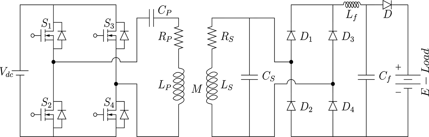
The circuit diagram of contactless charging system with SP compensation is depicted in Fig. 1. A DC voltage source V dc is applied to the input of H-bridge inverter. For the experiment purpose, a variable DC source is used to keep the current and voltage constant during charging of the battery bank in CC and CV modes, respectively.
Schematic of contactless charging system with SP compensation.

The compensated primary coil is excited with high-frequency current, generated by the high-frequency H-bridge inverter. On the secondary side, a parallel compensated coil is connected with a diode bridge rectifier, which converts high-frequency AC voltage to DC voltage. In order to get pure DC voltage and current, LC filter is used. Diode D ensures charging of the battery bank only when the anode voltage is greater than the cathode voltage. The battery bank is represented as E-Load. The symbols R P and R S denote AC resistance of the primary and secondary coils, respectively.
The primary and secondary compensation capacitors C P and C S are calculated at resonance frequency ω o , using (1) and (2), respectively [Reference Joy, Kushwaha, Rituraj and Kumar6, Reference Aditya and Williamson8, Reference Aditya and Williamson9, Reference Jiang, Wang, Chen, Wang and Wang13].
 $$C_P = \displaystyle{1 \over {\omega _o^2 (L_P - (M^2/L_S))}},$$
 $$C_S = \displaystyle{1 \over {\omega _o^2 L_S}},$$
where L P and L S represent the primary and secondary self-inductances, respectively.
B) Equivalent model of the charging system
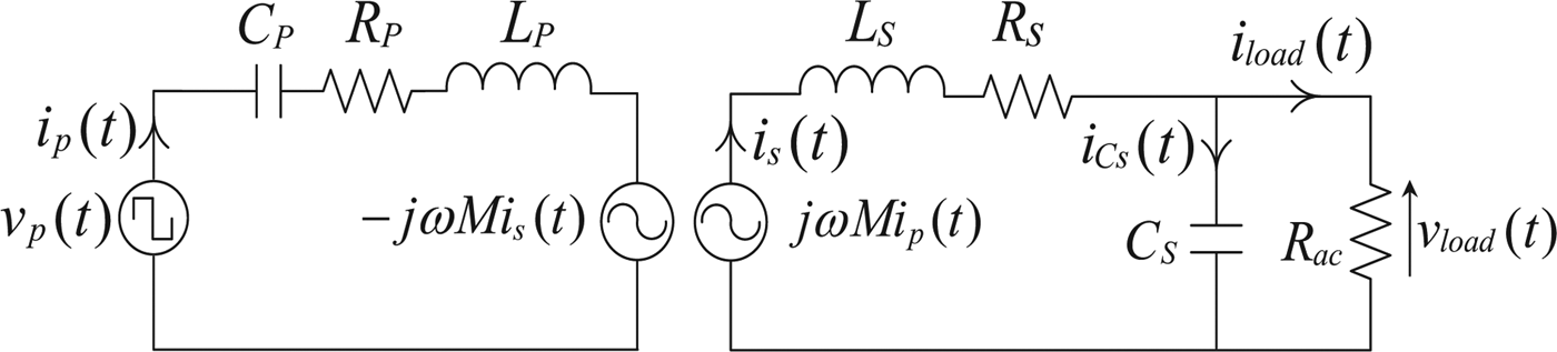
An equivalent circuit model of the charging system is shown in Fig. 2 [Reference Kushwaha, Rituraj and Kumar18]. The relation between coupling coefficient k and mutual inductance M is given in (3).
 $$k = \displaystyle{M \over {\sqrt {L_PL_S}}}, $$
 $$Z_P = R_P + j\left( {h\omega L_P - \displaystyle{1 \over {h\omega C_P}}} \right),$$
 $$Z_r = \displaystyle{{{(h\omega M)}^2} \over {R_S + jh\omega L_S + \left( {R_{ac}/(1 + jh\omega C_SR_{ac})} \right)}},$$
 $$R_{ac} = \displaystyle{{\pi ^2} \over 8}R_L,$$
 $$\eqalign{Z_T & = R_P + j\left( {h\omega L_P - \displaystyle{1 \over {h\omega C_P}}} \right) \cr & \quad + \displaystyle{{{(h\omega M)}^2} \over {R_S + jh\omega L_S + \left( {(R_{ac}/1 + jh\omega C_SR_{ac})} \right)}}.}$$
Equivalent circuit model of the SP compensated CPT system.

For (4)–(7), Z P , Z r , Z T represent the primary side, reflected, and total impedances of the CPT system for h th harmonic, respectively. R ac is the effective load resistance, seen from the input side of the rectifier. R L is the equivalent load resistance of the battery bank, which depends on charging status of battery voltage and current [Reference Zheng15].
The Fourier series expressions of the primary instantaneous voltage v p (t) (inverter output) and current i p (t) are given in (8) and (9), respectively.
 $$v_p(t) = \sum\limits_{h = 1,3,5..}^\infty \displaystyle{{4V_{dc}} \over {\pi h}}\sin h\omega t,$$
 $$i_p(t) = \sum\limits_{h = 1,3,5..}^\infty \displaystyle{{4V_{dc}} \over {\pi h \vert Z_T \vert}} \sin (h\omega t - \theta _{Z_T}),$$
where
 $\theta _{Z_T}$
is the load phase angle of total impedance Z
T
, seen from the output of H-bridge inverter.
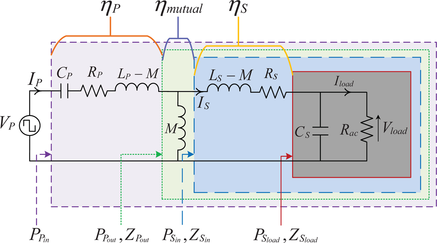
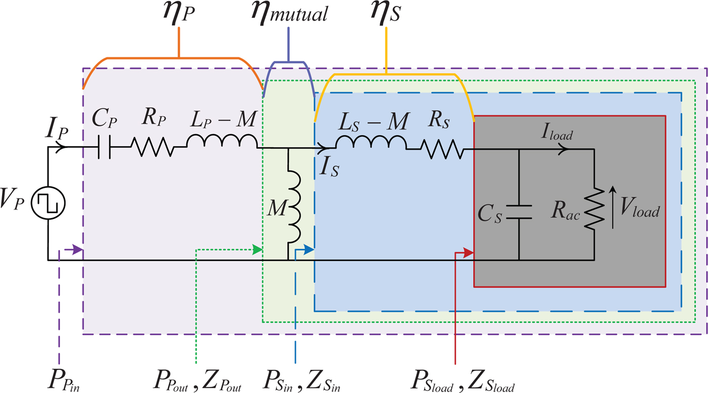
The compensated coil (transmission) efficiency η cc of the SP compensated CPT system is calculated using AC equivalent circuit based on T-model of contactless coils, as shown in Fig. 3. Equivalent series resistance of C P and C S are not considered in the efficiency calculation due to its insignificant effect. Hence, the real power consumed in capacitor is zero, and the η cc of the SP compensated CPT system is given as
 $$\eta _{cc} = \eta _P \cdot \eta _{mutual} \cdot \eta _S,$$
where η
P
, η
mutual
, and η
S
are the efficiencies of the equivalent primary, mutual, and secondary of the system, respectively. Since the mutual has only a reactive component, the active power consumed is zero (η
mutual
= 1). From Fig. 3,
 $\eta _P = P_{P_{out}}/P_{P_{in}}$
and
 $\eta _S = P_{S_{load}}/P_{S_{in}}$
, where the input power
 $P_{P_{in}} = (P_{P_{out}} + {\rm loss}\;{\rm in}\;R_P)$
and
 $P_{S_{in}} = (P_{S_{load}} + {\rm loss}\;{\rm in}\;R_S)$
. Therefore, the expression (10) can be written as
 $$\eta _{cc} = \displaystyle{{\Re (Z_{P_{out}})} \over {\Re (Z_{P_{out}}) + R_P}} \cdot 1 \cdot \displaystyle{{\Re (Z_{S_{load}})} \over {\Re (Z_{S_{load}}) + R_S}},$$
where the symbol
 $\Re $
represents the real part of the respective impedances,
 $Z_{S_{load}} = R_{ac}/(1 + j\omega C_SR_{ac})$
, and
 $Z_{P_{out}} = j\omega MZ_{S_{in}}/(j\omega M + Z_{S_{in}})$
. By substituting
 $Z_{S_{load}}$
and
 $Z_{P_{out}}$
in (11), the final expression of η
cc
is given as
 $$\eta _{cc} = \displaystyle{{M^2\omega ^2R_{ac}} \over {(C_S^2 R_{ac}^2 (L_S^2 R_P + M^2R_S)\omega ^4 + A\omega ^2 + R_P(R_S^2 + 2R_SR_{ac} + R_{ac}^2 )}},$$
where
 $A = (((C_S^2 R_S^2 - 2C_SL_S)R_{ac}^2 + L_S^2 )R_P + M^2(R_S + R_{ac}))$
and ω = 2πf.
AC equivalent circuit based on T-model of contactless coils for SP compensated CPT system.
From (12), the optimum operating frequency (f optimum ), at which the maximum η cc is achieved, can be obtained by (13) and is given in (14).
 $$\left. {\displaystyle{{\partial \eta _{cc}} \over {\partial f}}} \right \vert _{f_{optimum}} = 0,$$
 $$f_{optimum} = \displaystyle{1 \over {2\pi}} \displaystyle{{R_P^{1/4} \sqrt {R_S + R_{ac}}} \over {\sqrt {R_{ac}C_S} {(L_S^2 R_P + M^2R_S)}^{1/4}}}.$$
III. EXPERIMENTAL DISCUSSION
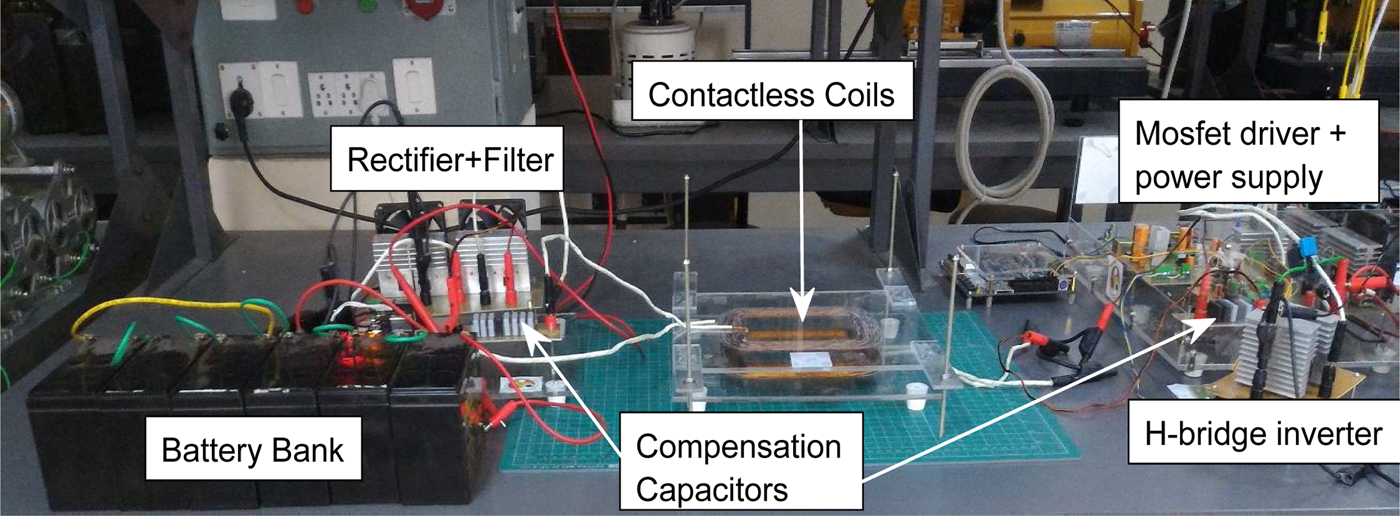
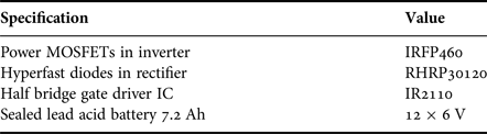
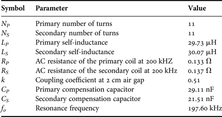
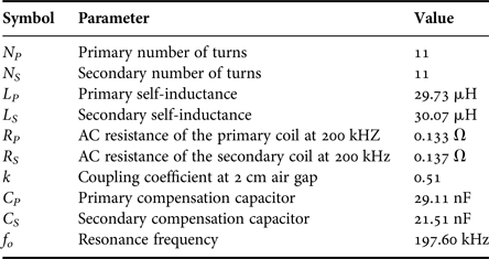
Figure 4 shows the laboratory view of real-time implementation for charging the battery bank using SP compensated CPT system. Six number of sealed maintenance-free lead acid batteries connected in series are used as a battery bank in the experiment. However, the other technologies of batteries like lithium, sodium, etc. can also be used. The details of power switches and the battery bank used in CPT system are provided in Table 1. The primary and secondary coils are made using Litz wire, having American wire gauge #32 copper wire. The vertical distance between primary and secondary coils can be adjusted up to 10 cm, while in the experiment it is kept at 2 cm. A resonance frequency of 197.60 kHz is selected for the SP compensated CPT system. To vary the output frequency of H-bridge inverter, a pulse width modulation controller IC SG3525A is used. The remaining specifications of the SP compensated CPT system are given in the Table 2.
Laboratory view of the experimental setup.

Specifications of power components and battery bank.

Specifications of the SP compensated CPT system.
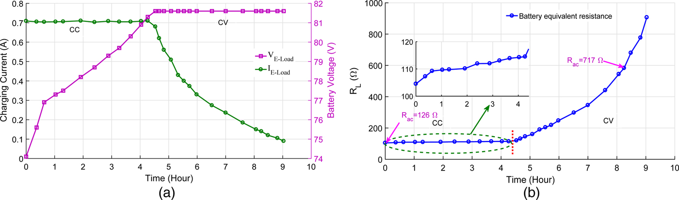
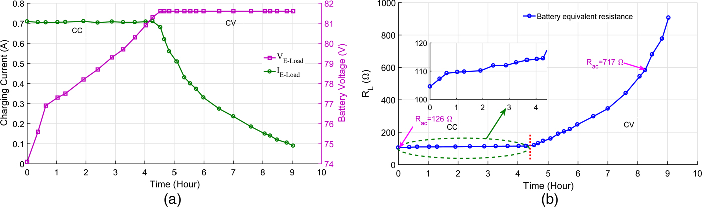
The charging of lead acid battery bank is performed in open loop (by manually controlling the input DC voltage to maintain CC and CV modes) at the resonance frequency. The measured charging profile and the equivalent resistance profile of a lead acid battery bank are shown in Fig. 5. The initial voltage of the battery bank is 74.1 V, which is first charged in CC mode for about 4 h, then in CV mode for about 5 h, as shown in Fig. 5(a). The charging current in CC mode is set to a constant 700 mA. Whereas, in CV mode, the voltage across the battery is maintained at 81.6 V by decreasing the input DC voltage. This results in a decrease in the charging current. The equivalent resistance profile of battery bank, as shown in Fig. 5(b), is obtained from Fig. 5(a).
(a) Measured charging profile and (b) equivalent resistance profile of a lead acid battery bank at the resonance frequency.
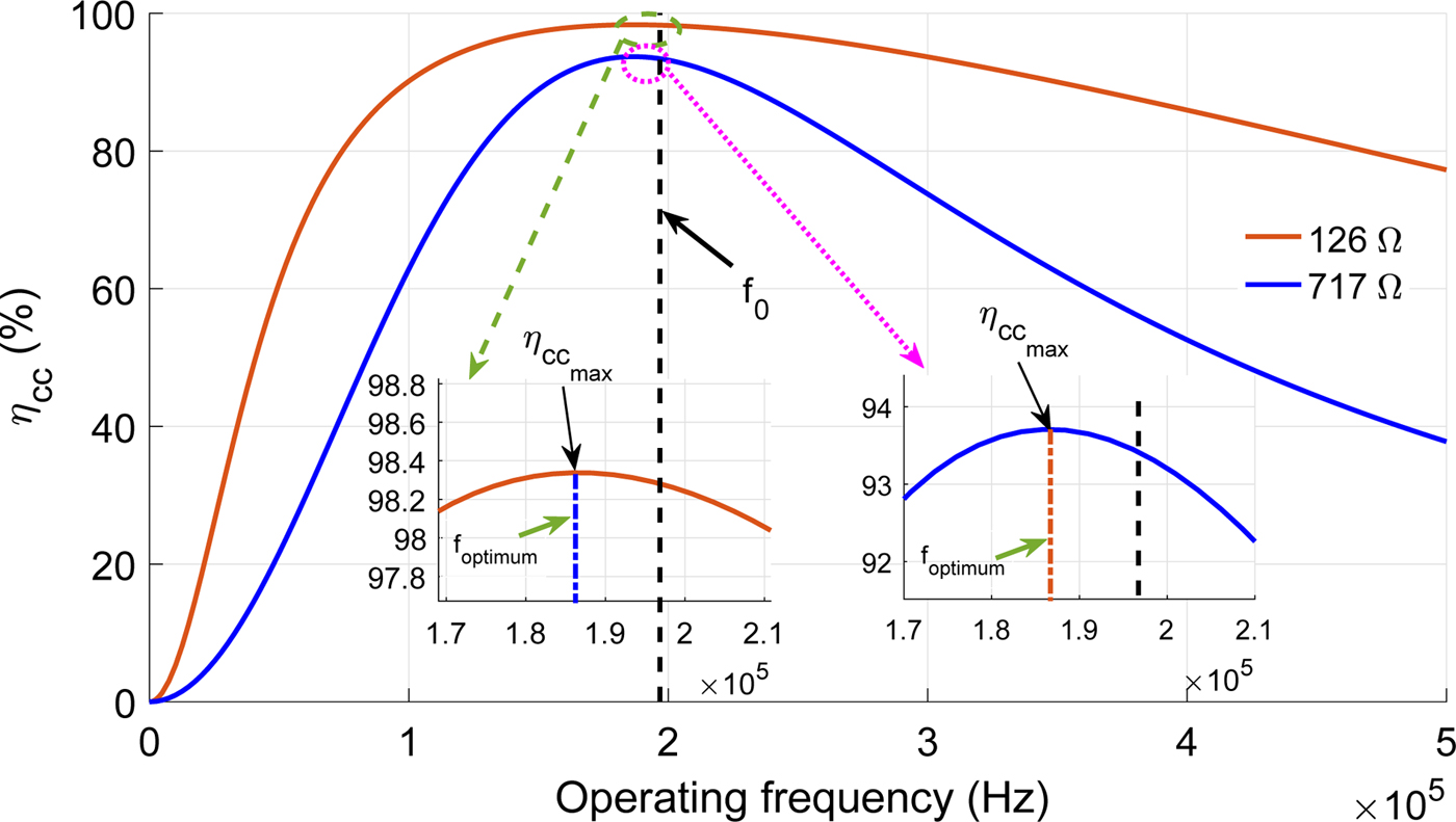
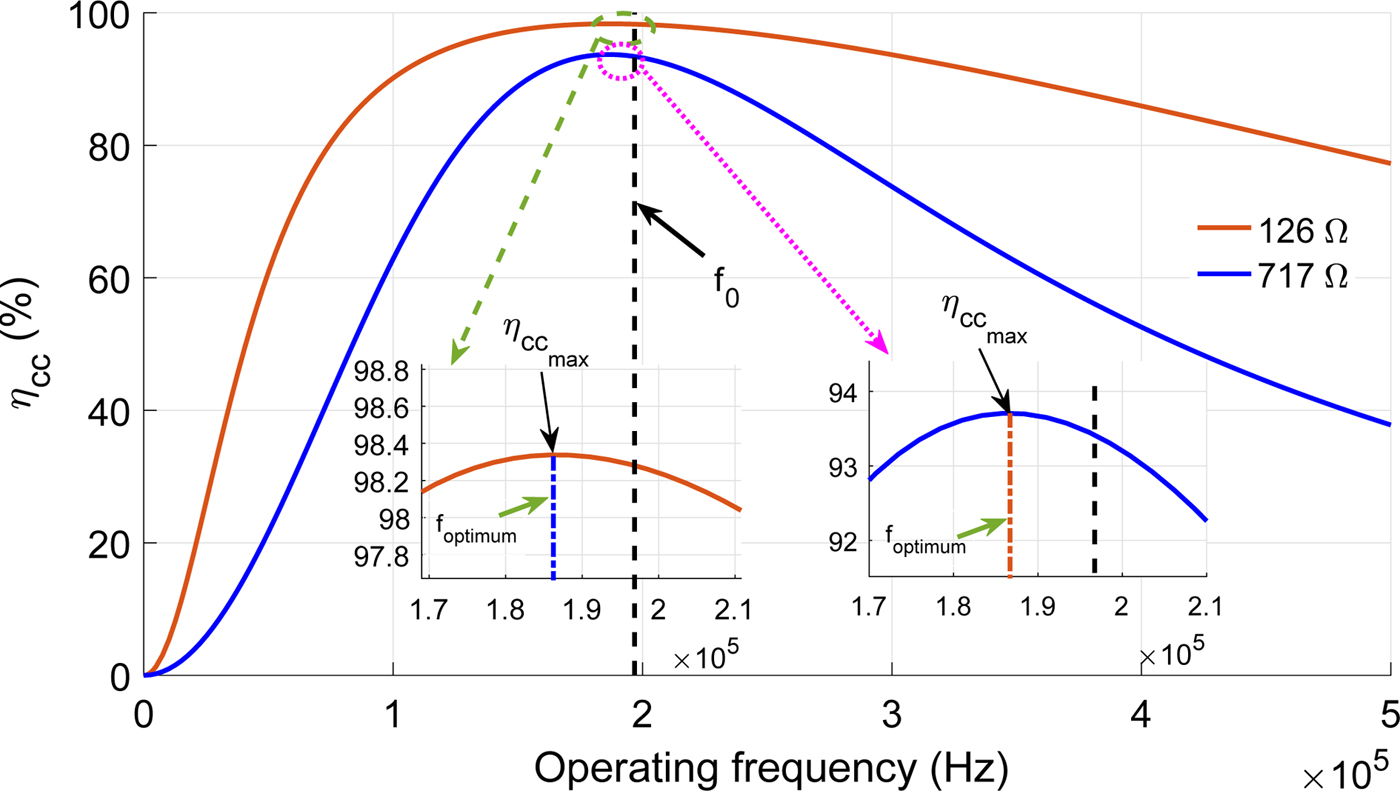
In Fig. 6, the variation of compensated coil efficiency, calculated from (12), with respect to (w.r.t.) different operating frequencies (0–500 kHz) for R
ac
= 126 Ω and 717 Ω, is given. Two cases for the variation in compensated coil efficiency are presented in Fig. 6. One is for the CC mode (R
ac
= 126 Ω) and another is for the CV mode (R
ac
= 717 Ω). For both the cases in Fig. 6, the maximum compensated coil efficiency (
 $\eta _{cc_{max}}$
) is shown by zooming the dotted circle area. From the zoomed version, it can be seen that
 $\eta _{cc_{max}}$
lies on the left side of the resonance frequency (f
0), marked as a f
optimum
. Further investigation on
 $\eta _{cc_{max}}$
and ZVS at different operating frequencies in CC and CV modes with the experimental results has been done from the next paragraph.
Variation of calculated compensated coil efficiency w.r.t. different operating frequencies for R ac = 126 Ω and 717 Ω.
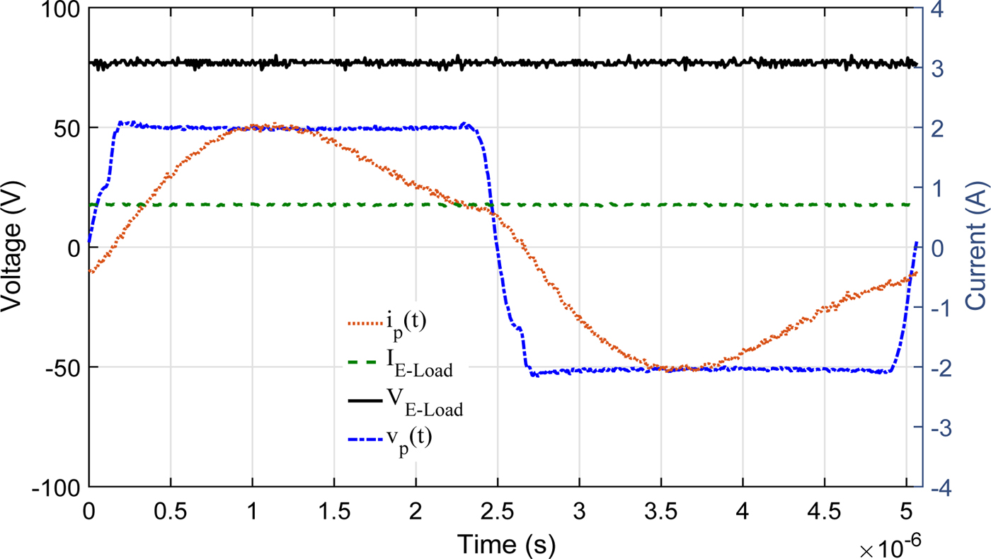
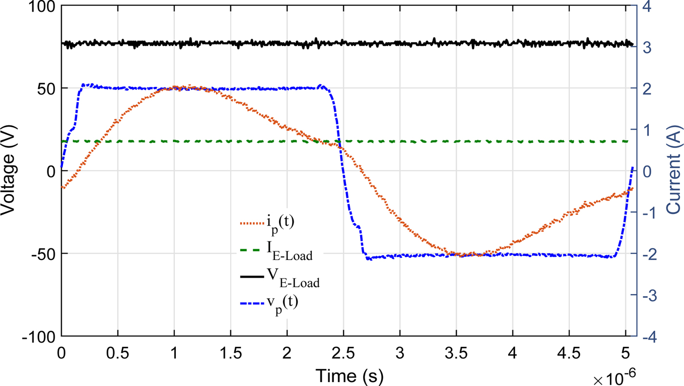
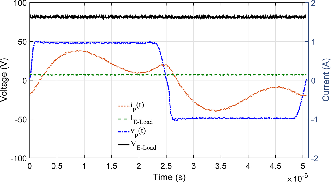
At the time of charging in CC and CV modes, the voltage and current waveforms of the inverter and battery bank are observed. In CC mode, the waveforms are recorded for inverter output and battery bank, as shown in Fig. 7. Since the current is constant in CC mode, an effective load resistance R ac will change only due to the voltage rise, which is less significant, as shown in Fig. 5(b). In CC mode, at a particular instant of time, R ac is experimentally measured as 126 Ω [marked in Fig. 5(b)]. Since the electrical characteristics of the battery bank will change over the time, the battery bank is replaced by an equivalent resistive load of 126 Ω to maintain same R ac for further experiment.
Experimental waveforms in CC mode at the resonance frequency.
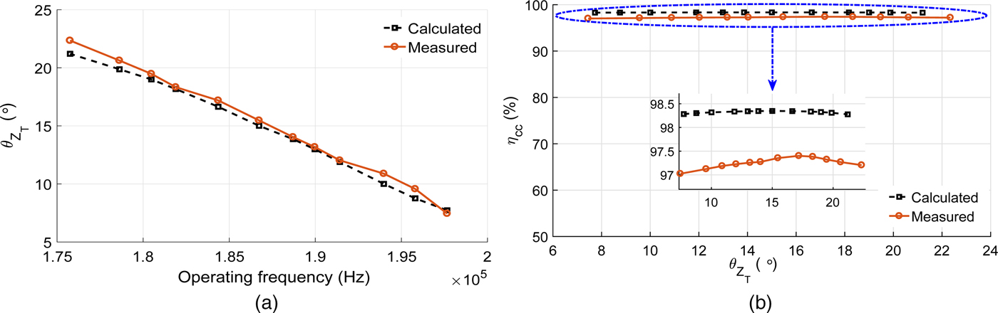
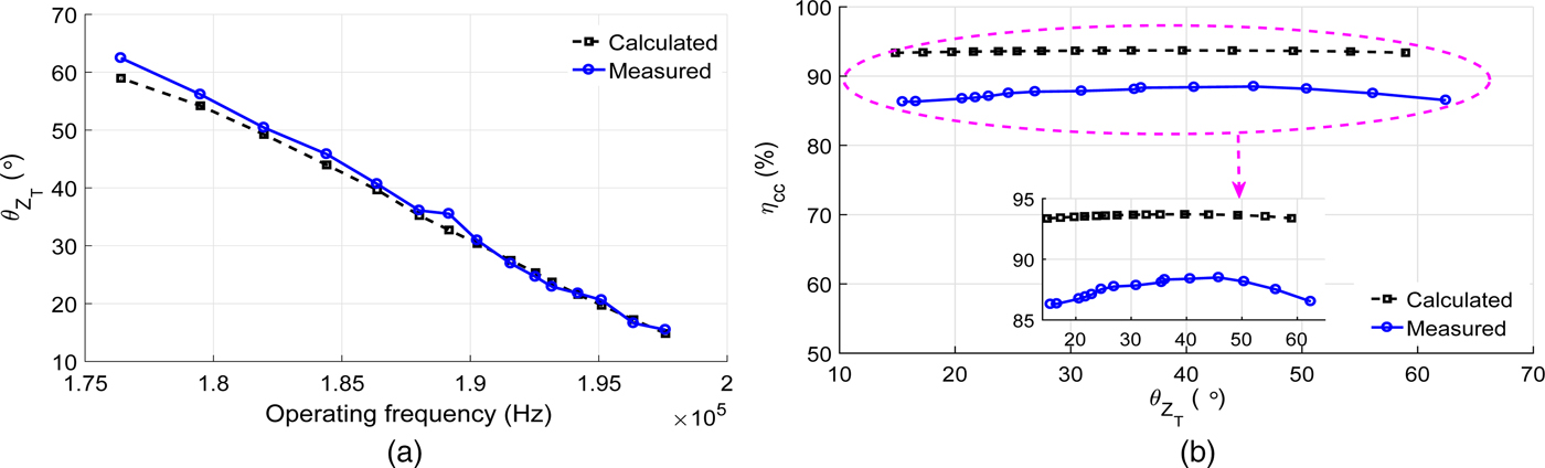
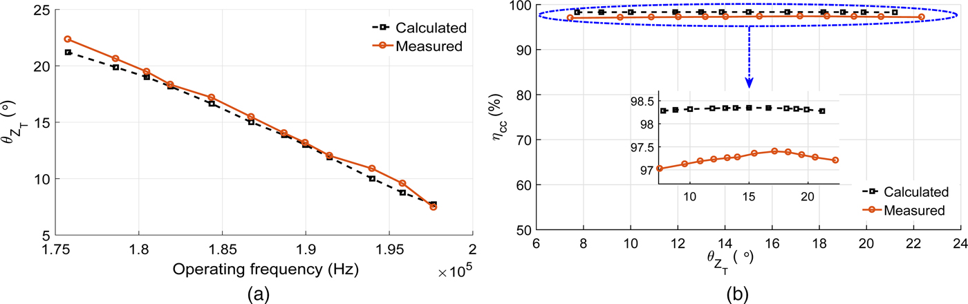
In Fig. 8(a), the variation of load phase angle obtained from (9) and measured from the experiment are shown for different operating frequencies when R ac = 126 Ω. It can be observed from Fig. 8(a) that both the curves are following the same nature. It can also be seen that to increase the load phase angle of the system, operating frequency should be decreased from its resonance frequency. The plot of η cc versus load phase angle obtained from (9) and (12), and measured from the experiment, is given in Fig. 8(b). From Fig. 8(b), an almost constant nature of η cc is seen with variation in the load phase angle. However, in zoomed version, a parabolic nature is seen with an increase in load phase angle. Hence, it has a maximum efficiency point, which is about 15° from the calculation and 17° from the measurement.
Experimental results at R ac = 126 Ω. (a) Load phase angle versus operating frequency and (b) compensated coil efficiency versus load phase angle.
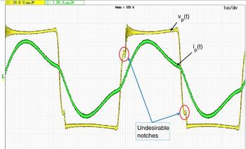
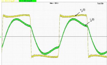
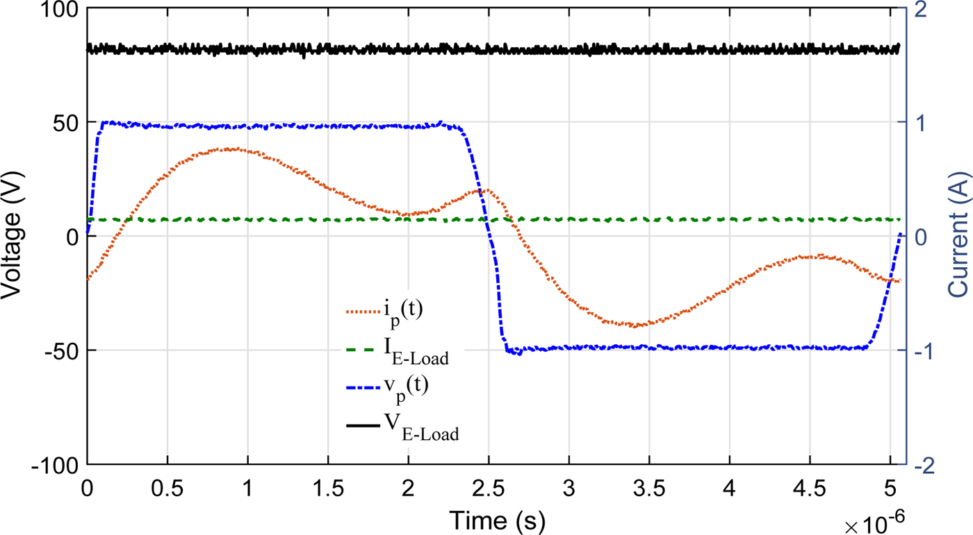
At resonance frequency, the experimental waveforms of primary voltage (inverter output) and current are given in Fig. 9. In Fig. 9, undesirable notches (due to inappropriate ZVS), marked in the red circle are noticed in the primary voltage waveform, which can affect the system stability. An improved waveform (due to proper ZVS) of the primary voltage is recorded at 184.3 kHz frequency (measured f optimum ), which is about 17° of load phase angle, as shown in Fig. 10.
From Figs 8–10, it can be seen that to obtain a stable performance, load phase angle should be increased by decreasing the operating frequency to f optimum . In this way, the system stability can be improved with a maximum efficiency for lower load resistance in CC mode.
Experimental waveforms of primary voltage and current (inverter output) at 197.6 kHz operating frequency (resonance frequency) and R ac = 126 Ω.

Experimental waveforms of primary voltage and current (inverter output) at 184.3 kHz operating frequency and R ac = 126 Ω.

In CV mode, the voltage and current waveforms of inverter output and battery bank are recorded at the end stage of CV mode for a charging current of 140 mA, as shown in Fig. 11. An effective load resistance R ac is experimentally measured as 717 Ω [marked in Fig. 5(b)], which is higher than CC mode. To maintain R ac (717 Ω), the battery bank is replaced with the resistive load for further experiment.
Experimental waveforms in CV mode at the resonance frequency.
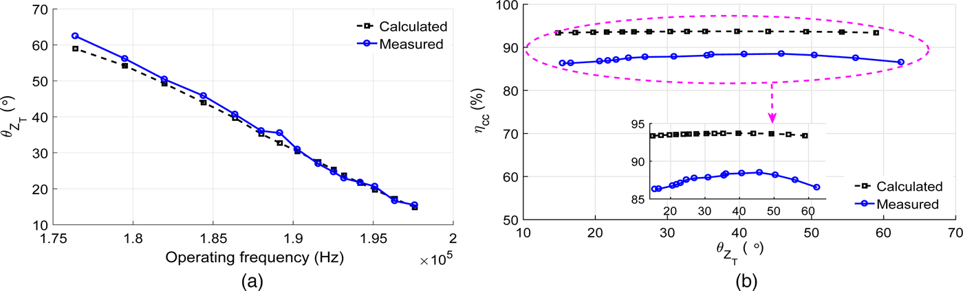
At R ac = 717 Ω, again operating frequency is varied to maintain ZVS with maximum efficiency. The variation of load phase angle for different operating frequencies obtained from (9) and measured from the experiment when R ac = 717 Ω is plotted in Fig. 12(a), and the η cc observed at each load phase angle calculated from (9) and (12) is given in Fig. 12(b). From Fig. 12(a), it can be examined that both the curves are following the same pattern. In CV mode, the waveform of inverter voltage is stable throughout the variation, even at the resonance frequency, as shown in Fig. 11. From Fig. 12(b), it is observed that the η cc is maximum when load phase angle is about 40° (obtained at f optimum = 186.5 kHz) from the calculation and about 45° (obtained at f optimum = 184.4 kHz) from the measurement. In addition, a parabolic nature of the η cc curve is noticed with an increase in the load phase angle.
Experimental results at R ac = 717 Ω. (a) Load phase angle versus operating frequency and (b) compensated coil efficiency versus load phase angle.
From the above discussion, it can be noticed that, by controlling the load phase angle in both CC and CV modes, a stable performance and maximum efficiency can be achieved.
IV. CONCLUSION
An experimental analysis in open loop for the lead acid battery charging using the SP compensated CPT system is presented. Measured charging profile and the equivalent resistance profile of the lead acid battery bank are presented in CC and CV modes. Lower to higher variations in R ac are observed during the charging process. An expression of optimum operating frequency is derived to get the maximum compensated coil efficiency during the load variation in charging process. An open-loop control is performed to ensure the system stability and maximum efficiency at obtained optimum operating frequency in CC and CV modes. From the experimental results and discussion, a suitable closed-loop robust controller can be implemented.
 Gautam Rituraj received the B.Tech. degree in Electrical Engineering from the Uttar Pradesh Technical University, Lucknow, India, in 2012. He is currently pursuing the Ph.D. degree with the Department of Electronics and Electrical Engineering, IIT Guwahati, Guwahati, India. His current research interests include the analysis and design of stationary wireless power transfer systems and developing the power electronic circuits for electric vehicle charging.
 Brijesh Kumar Kushwaha received the B.Tech. degree in Electronics and Communication Engineering from the Uttar Pradesh Technical University, Lucknow, India, in 2010, and the M.Tech. degree in Power Electronics and Application Specified Integrated Circuit Design from the Motilal Nehru National Institute of Technology, Allahabad, India, in 2012. He is currently pursuing the Ph.D. degree with IIT Guwahati, Guwahati, India. His current research interests include the modeling of wireless power transfer systems, magnetic field theory, and power electronics.
 Praveen Kumar received the B.Tech. degree in Electrical Engineering from the National Institute of Technology, Hamirpur, India, in 1998, the M.Tech. degree in Energy System from the IIT, Delhi, India, in 2000, and the Ph.D. degree from the Delft University of Technology, Delft, The Netherlands. He is currently an Associate Professor with IIT Guwahati, Guwahati, India. He was a Team Leader of Hybrid Systems with Drive Trains Innovation, Eindhoven, The Netherlands. His current research interests include optimization of electrical motors and drives, hybrid and electric vehicles, smart grid, and wireless charging of electric vehicles.