I. INTRODUCTION
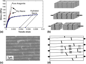
Materials produced by nature exhibit remarkable properties that are attracting the attention of engineers, material scientists, chemists, and zoologists in search of inspiration for novel material designs.Reference Barthelat1 Often made of materials with relatively poor structural qualities, biological materials achieve their performance through intricate microstructures finely tuned over millions of years of evolution.Reference Wegst and Ashby2–Reference Meyers, Chen, Lin and Seki4 Elucidating the structure– properties relationships in these materials is a challenging task, but is nevertheless an essential step for a successful biomimetic “transfer of technology” from natural to synthetic materials and systems. Nacre from mollusk shells, also known as mother of pearl, is now identified as an excellent model for high-performance materials offering attractive combinations of stiffness, strength, and toughness.Reference Barthelat5 Nacre is a highly mineralized material made of 95% of the mineral calcium carbonate, which comes in the form of microscopic polygonal tablets closely stacked to form a dense, three-dimensional (3D) brick wall.Reference Currey6 The remaining constituents are proteins and polysaccharides, which form an organic matrix concentrated at the interfaces between the tablets.Reference Schaeffer, IonescuZanetti, Proksch, Fritz, Walters, Almqvist, Zaremba, Belcher, Smith, Stucky, Morse and Hansma7 Nacre is relatively stiff and hard compared to other biological materials,Reference Wegst and Ashby2 which is easily explained by its high mineral content. The most remarkable and less obvious property of nacre is actually its toughness, which is 3000 times that of the mineral it is made of (in J IC terms).Reference Wegst and Ashby2 Much of this toughness is explained by nacre’s ability to deform past a “yield point” and to develop large inelastic strains over large volumes around defects and cracks. This mechanism generates tremendous toughness amplification,Reference Barthelat and Rabiei8 effectively making nacre damage tolerant.Reference Evans, Suo, Wang, Aksay, He and Hutchinson9 Failure strains in nacre exceed 1% [Fig. 1(a)],Reference Barthelat and Espinosa10 which is 100 times the typical failure strain of engineering ceramics. These high strains in nacre are now well explained by two mechanisms. First, the tablets have the ability to “slide” on one another when nacre is subjected to tension [Fig. 1(b)].Reference Currey6, Reference Jackson, Vincent and Turner11, Reference Wang, Suo, Evans, Yao and Aksay12 This sliding is mediated by soft organic materials that provide cohesion over large sliding distancesReference Smith, Schaeffer, Viani, Thompson, Frederick, Kindt, Belcher, Stucky, Morse and Hansma13 and possibly lubrication.Reference Evans, Suo, Wang, Aksay, He and Hutchinson9 In addition, nanoscale mineral features at the interface can increase the resistance to sliding.Reference Evans, Suo, Wang, Aksay, He and Hutchinson9, Reference Wang, Suo, Evans, Yao and Aksay12 These combined features are necessary for large deformation, but they are not sufficient. A hardening mechanism has to operate to spread the sliding mechanism over large volume and to delay strain localization to maximize energy dissipation at the interfaces. This second key mechanism has recently been demonstrated to be generated by the waviness of the tablets, which makes the ends of some tablets thicker at the periphery than near the center, effectively providing low-angle dovetails.Reference Barthelat, Tang, Zavattieri, Li and Espinosa14 Under tension, these dovetails provide progressive locking stresses that impede tablet sliding and generate hardening [Figs. 1(c) and 1(d)]. The “core” of each column (central region of the tablets) is also reinforced by mineral bridges,Reference Song and Bai15 which probably add stability to the structure and prevents delamination.
(a) The stress–strain curve of nacre in tension showing strain hardening and relatively large strains at failure for hydrated nacre; (b) the large strains are generated by sliding of the microscopic mineral tablets on one another; (c) scanning electron microscopy showing nacre tablets with dovetail ends; (d) transverse compressive stresses are generated at the dovetail, generating resistance to pullout. These stresses are balanced by transverse tensile stresses in other regions (gray arrows).

The unique architecture and mechanisms of nacre and how they lead to its impressive mechanical performance have motivated the development of numerous “artificial nacres” over the past 20 years.
Various fabrication techniques were used, including innovative and ingenious approaches, such as layer-by-layer deposition,Reference Tang, Kotov, Magonov and Ozturk16, Reference Podsiadlo, Paternel, Rouillard, Zhang, Lee, Lee, Gulari and Kotov17 bottom-up colloidal assembly,Reference Bonderer, Studart and Gauckler18 centrifugal deposition process,Reference Almqvist, Thomson, Smith, Stucky, Morse and Hansma19, Reference Chen, Wang, Huang and Le20 shearing cylinders, sedimentation and dipping,Reference Almqvist, Thomson, Smith, Stucky, Morse and Hansma19 in situ polymerization into porous ceramics,Reference Pezzotti, Asmus, Ferroni and Miki21 molecular scale self-assembly and biomineralization,Reference Li and Kaplan22 or ice-templated sintering of alumina powders.Reference Munch, Launey, Alsem, Saiz, Tomsia and Ritchie23 These materials successfully duplicate several features of natural nacre: unidirectional micron- or submicron-size mineral tablets with high aspect ratio embedded in softer, ductile polymeric matrices. However, while these materials display structures that closely resemble nacre, none could truly duplicate its mechanism of tablet sliding with progressive locking. This is a significant lack, and as a result, the toughness amplification of these materials is still inferior to natural nacre. For example, the ice-templated technique currently yields the material closest to nacre in terms of structure and properties: hybrid composites made of 80% of aluminum oxide and 20% of PMMA, which are 300 times tougher than their constituents (in J IC terms). Although this is an impressive performance, it is still a relatively small improvement compared to natural nacre (which is 3000 times tougher than aragonite). The hybrid composites duplicate the brick-and-mortar structure of nacre and “pull-out” between the bricks was observed. However, natural nacre’s progressive locking mechanism and massive tablet sliding mechanism could not be replicated in the Al2O3/PMMA composites.
Perhaps the main reason for the only moderate success in duplicating the toughness amplification of nacre is the tremendous challenges involved in controlling the architecture of the materials at the micro- and nanoscales. Natural nacre has a highly regular tiling of tablets and well-defined features at the nanoscale, resulting from complex self-assembly and biomineralization processes. Significant research efforts are currently underway to harness these processes to fabricate engineering materials, but “growing” bulk materials using these approaches is not possible to this day.
An alternative approach to alleviate this major fabrication challenge is to “relax” the length-scale condition and to produce structures with millimeters rather than with micrometer-length scales. Current fabrication technologies allow a far greater control over geometries and structures in the millimeter scale, which can be harnessed to duplicate specific features in natural nacre. Recent work by Espinosa et al.Reference Espinosa, Rim, Barthelat and Buehler24 followed this approach: rapid prototyping was used to produce a two-dimensional (2D) tiling resembling nacre, including tablet overlap and waviness in the form of dovetails. The mechanical response showed softening at first followed by some locking and the beginning of spreading of deformation. The strain hardening, progressive locking, and massive spreading of inelastic distribution observed in natural nacre could, however, not be replicated.
In parallel, mechanistic models were developed to capture the salient mechanisms of nacre. Previous studies have used micromechanical modeling and finite element models to predict the mechanical behavior of nacre. Evans et al.Reference Evans, Suo, Wang, Aksay, He and Hutchinson9 developed a model for the inelastic behavior, measured in tension, along the axis of the aragonite plates. The model is based on observations for abalone nacre that the inelasticity is generated by tablet sliding. The model calculates the stresses involved in sliding tablets with nanoscale asperities. Kotha et al.Reference Kotha, Li and Guzelsu25 used a 2D model to analyze the stress transfer between the aragonite tablets and simulate the tensile behavior of nacre. They suggested that composites having high toughness can be made using platelets with small aspect ratios, but the matrix should be designed to have high shear strains. Barthelat et al.Reference Barthelat, Tang, Zavattieri, Li and Espinosa14 presented 3D-representative volume elements that revealed that even in the absence of nanoscale-hardening mechanism at the interfaces, the microscale waviness of the tablets could generate strain hardening, thereby spreading the inelastic deformation and suppressing damage, leading to material instability. Tushtev et al.Reference Tushtev, Murck and Grathwohl26 studied the mechanisms behind the elastic properties of nacre under tensile and shear loads, using finite element simulations. They suggest that the mineral bridges between adjacent platelets enhance the stiffness of nacre under shear and transversal tension. Recently, Barthelat and RabieiReference Barthelat and Rabiei8 presented a model capturing the salient mechanisms involved in the cracking of a staggered structure and showed that the pullout of inclusions and large process zones lead to tremendous toughness by far exceeding that of individual components. The model also provided insights into microstructure–property relationships useful in the context of biomimetics. This body of modeling work on nacre demonstrates that tablet sliding is critical to the toughness of nacre and that “perturbations” on the surface of the tablets are necessary to generate resistance to sliding and even hardening.
In this article, a novel composite based on the structure and mechanics of nacre is presented. This composite was based on millimeter-size PMMA tablets, constructed following the brick and mortar arrangement of natural nacre in a 2D tiling. In place of the mineral bridges present in the core regions of nacre, transverse fasteners were used to hold the tablets together. The tablets duplicated the waviness of natural nacre to generate hardening and spread deformations. The first section of the article presents an overview of the structure, mechanics, fabrication, and testing of this new material. The mechanics is further explored in the second section, where analytical and finite element models are presented and compared with the experiments.
II. OVERVIEW OF THE COMPOSITE
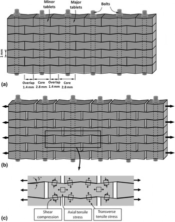
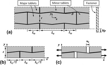
The objective of this work was to fabricate a material that incorporated the structural features required to duplicate the tablet sliding mechanism observed in natural nacre. The proposed nacre-like composite material is showed in Fig. 2(a). Its main features directly borrow the following design features of natural nacre:
(i) Stiff and brittle tablets are arranged in a columnar fashion with well-defined overlap and core regions. This arrangement is achieved by alternating long tablets (major tablets) with shorter tablets (minor tablets). The tablets were machined from poly-methyl-methacrylate (PMMA), which was chosen for its machinability and for its relative stiffness and brittleness compared to other polymers.
(ii) Interfaces between the tablets that maintain cohesion over long sliding distances: Here, no material was actually used at the interfaces and direct contact and dry friction controlled the interaction between the tablets.
(iii) Waviness on the tablets to generate strain hardening and spread deformations: Here, a triangular-shaped waviness was implemented on the surface of the tablets, which generated dovetail features at the ends of the major and minor tablets.
(iv) Reinforcements in the core regions: In natural nacre, mineral bridges, concentrated in the center of the tablets, reinforce the core regions and prevent delamination. In the proposed material, these bridges were replaced by transverse fasteners that hold the tablets together and reinforce the core.
Overview of the nacre-like composites: (a) schematic with dimensions; (b) under tension tablets slide with progressive locking; (c) some of the stresses involved in progressive locking.

The anticipated behavior in tension of such composite is showed in Fig. 2(b). Tablets slide on one another and progressive locking spreads inelastic deformations over the entire material, which successfully duplicates the behavior of nacre [Fig. 1(b)]. As a result, the strain at failure and the energy dissipated through friction are expected to be several times that of the tablets themselves. With flat tablets, the deformation would inevitably lead to immediate localization of strains. The dovetails are critical to generate progressive locking, and the stresses involved in this mechanism are shown in Fig. 2(c). In addition to dry friction, the dovetails generate transverse compressive stresses in the overlap regions, which increase with sliding distance and generate hardening. Transverse compression is balanced by transverse tension in the core region, which can become high enough to delaminate the tablets. Delamination immediately shuts the locking mechanism and leads to premature failure. A preliminary finding that leads to this prototype was that no synthetic glue could prevent delamination while allowing for tablet sliding. Fasteners were, therefore, chosen to hold the tablets together, emulating the mineral bridges observed in the core regions of nacre.
III. FABRICATION AND TESTING
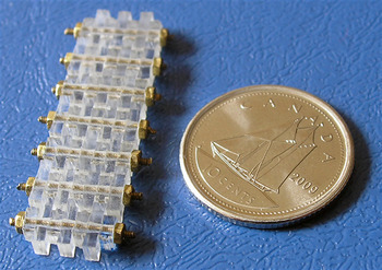
As a first fabrication step, 50-mm by 50-mm PMMA plates were cut from a 1.5-mm thick PMMA sheet. An end mill sharpened at a 5° angle was used on a computer numerical control (CNC) milling machine to generate the wavy features on the surface of the plates, and a small-diameter end mill was then used to machine the deep grooves that defined the ends of the tablets. The PMMA plate was then flipped and the machining process was repeated on the other face. A special fixture was used to ensure that the features on both faces were properly aligned. As a final machining step, an array of holes with a diameter of 1.0 mm was machined through the centers of the tablets. The tablets were then separated manually, and after sonication and cleansing with ethanol, they were assembled on 0.8-mm diameter stainless steel rods and nuts to form a nacre-like structure. The resulting material, shown on Fig. 3, consisted of seven layers and were composed of eight columns of tablets. The nuts were either lightly tightened by hand (“snug-tight”) or tightened using a wrench. The amount of tightening was then controlled by counting the fraction of turns imposed on the nuts. Tightenings of ¼ turn and ½ turn were used here. Tightening the bolt beyond ½ turn resulted in damage to the tablets (yielding and cracking).
Actual composite after assembly.

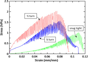
The resulting material was tested in uniaxial tension along the direction of the tablets, using a miniature loading stage (Ernest F. Fullam Inc., Latham, NY). The sample was held in place by clamping the end columns of tablets. The setup was then placed under a digital camera equipped with a macro lens. The sample was stretched at a rate of 3.0 mm/min (corresponding to a strain rate of 2.8 × 10⁻³ s−1), until the specimen failed, and images were captured at regular intervals to keep track of deformations and failure. The stress–strain curves resulting from this tensile test are shown in Fig. 4. After a short linear region, the material enters a nonlinear region with significant strain hardening. In this region, the tablets are sliding on one another, the dovetail geometry providing progressive locking and hardening following the scenario is shown in Fig. 2(b). For all the cases, the signal was noisy after certain strain level depending on the amount of tightening on the fasteners, and the sample emitted a rattling noise during the test, which was attributed to stick-slip phenomena associated with dry friction. As the tablets slide and hardening develops, the contact area between the tablets diminishes, which decreases the amount of force transferred at the interfaces. This softening phenomenon competes with hardening until the stress reaches its maximum value, after which softening prevails and a strain localization appears: any additional stretch imposed on the sample generates tablet separation in only a single overlap region, the other being “frozen” at the same stage of sliding. Complete separation of the composite occurred at strains of about 12%, which is 3–5 times higher than the strain at failure of PMMA. This nacre-like mechanism can, therefore, effectively turn a relatively brittle material into a ductile one. Interestingly, tightening the fasteners increased the maximum stress. This is explained by the following: (i) the initial transverse compression between tablets is higher, and therefore, the friction force is higher and (ii) higher transverse compression delays delamination between the tablets, which sustains the strength of the locking mechanism.
Tensile stress–strain curves from the nacre-like composite for different amounts of tightening on the fasteners.

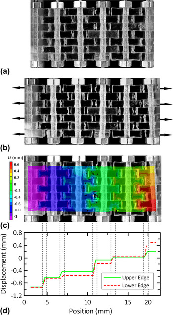
The inelastic deformations were monitored by imaging the specimen during the tensile test. Figures 5(a) and 5(b) show the material at rest and with 10% deformation (snug-tight case). Tablet sliding has spread in the entire specimen (localization eventually occurs, in this case, at the last overlap region on the right of the specimen). Figure 5(c) shows the displacement results from digital image correlation in Fig. 5(b). Displacement jumps across every potential sliding site are evident. The displacement was plotted as function of longitudinal position on the upper and lower edges of the specimen in Fig. 5(d). This again highlights the displacement jumps and also shows that the separation distance is different at the upper and lower surfaces. This is an indication that the columns of tablets also rotate during sliding and that the overlap regions actually progressively fail by “unzipping.” This instability is probably triggered by little amount of misalignment of the individual tablets during assembling process or preexi-sting defects in the assembly. The implications of this mechanism are significant and are discussed below.
Progressive deformation within the sample at increasing macroscopic strains: (a) undeformed; (b) deformed; (c) displacement using digital image correlation; (d) displacement profile of the upper and lower edges. In the deformed sample, tablet sliding spreads throughout the sample.

This first “model material,” therefore, demonstrates how the powerful hardening mechanisms occurring in natural nacre can be harnessed in engineering materials. The mechanism of tablet sliding can be duplicated in synthetic material by transposing only a few key structural features from natural nacre. Although this material could demonstrate this process, in its current form it has a very low modulus and low tensile strength (less than 2 MPa), limiting potential engineering applications. There is, however, a significant potential for improvement. PMMA can be replaced by a stiffer and stronger material, such as a metal or an advanced ceramic. In addition, the microstructure of this material can be finely tuned and optimized according to the choice of materials to achieve useful combinations of stiffness, strength, and toughness. For the next generation of materials to be successful and optimized, models that accurately capture the progressive locking phenomena are needed. In the next section, models of increasing complexity are presented, and the experiments presented above then serve for their validation.
IV. REPRESENTATIVE VOLUME ELEMENT (RVE) MODELS
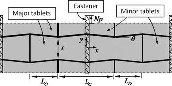
A 2D-analytical model of the nacre-like composite was first developed, with the aim of capturing the progressive locking mechanism and to identify key structural parameters. In this first model, the structure was assumed to be periodic in the two in-plane directions so that only the representative volume element showed in Fig. 6 was modeled.
Representative volume element (RVE) model.

The depth of the composite was smaller than the in-plane dimensions, and plane stress conditions were assumed (the model can, however, be easily transposed to plane strain). The tablets were modeled as linear elastic (modulus E and Poisson’s ratio ν). The sliding of the tablets at the interfaces was assumed to be controlled by Coulomb friction, with friction coefficient f. An analytical model could be derived to take into account the progressive locking of the elastic tablets and the effect of the fasteners (see Appendix for calculations). The main result from this model is the tensile stress–strain curve of the composite, given by

where  and
 are the stress and strain in the composite, respectively. The tensile stresses could be normalized by the modulus of the tablets E, with the immediate result that the elasticity of the tablets dominates the locking mechanism. Equation (1) is also a function of the nondimensional tablet aspect ratio
 , of the overlap ratio
 , of the nondimensional bolt stiffness
 (with Eb being the modulus of the bolt, A t its cross section, and w the depth of the RVE), and of the nondimensional bolt tightening
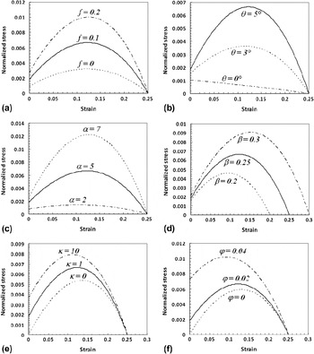
 (where p is the pitch of the thread and N is the fraction of turns given to tighten the fastener). Figure 7 shows the effect of each of these nondimensional parameters on the tensile stress–strain curve. Unless specified otherwise, the parameters for the “control” model used for comparison are α = 5, β = 0.25, θ = 5°, κ = 1, ϕ = 0.02, ν = 0.35, and f = 0.1.
Effect of the design parameters on the stress–strain response (stress is normalized by the modulus of the tablets): (a) friction coefficient; (b) waviness angle; (c) tablets aspect ratio; (d) tablet overlap ratio; (e) nondimensional bolt stiffness; and (f) nondimensional bolt tightening.

The overall shape of the stress–strain response is similar to the experiment as the model captures the competition between progressive locking and loss of contact surface area. The effect of increasing each of these parameters results in an increase in tensile stresses and strength. Friction, in combination with a preload on the fastener, increases the initial force required to initiate sliding. The dovetail angle has a significant effect on the curve, an angle of 0°, leading to no locking and to immediate softening of the material. Increased aspect ratio and overlap ratio both lead to increased strength, and the latter also lead to higher strain at failure (since a longer section of the tablet is available for pullout). Finally, stiffening the bolt or increasing initial tightening increases both initial stress and maximum stress. This trend is again consistent with the experimental observations. It is, therefore, possible to increase the strength of this material by tuning these parameters. There are, however, design limitation associated with detrimental failure modes. For example, increasing the dovetail angle increases the overall strength significantly, but this also means that the tensile stress carried by the tablets is increased. If this stress exceeds the tensile strength of the tablet, it will fracture and the benefit of tablet sliding will be lost. Although these limiting cases were not explored experimentally here, the model can be used to finely tune each parameter for optimum mechanical performance in improved versions of this composite.
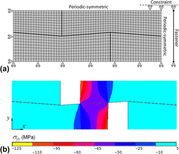
Although this relatively simple analytical expression for the stress–strain curve is convenient for parametric studies, several assumptions were made in its derivation. For this reason, the accuracy of that solution was assessed by comparison with a finite element model (Fig. 8). The model used the actual dimensions of the composite [Fig. 2(a)]. Only one quarter of the RVE was model using symmetries, and periodic-symmetric boundary conditions were imposed (see Appendix). The tablets had the elastic properties of PMMA (E = 2.3 GPa, obtained by three-point bending test; ν = 0.35Reference Biron27). The fastener was explicitly modeled with a bar element, whose end displacements were tied to the upper and lower edges of the RVE. The fastener had a diameter of 0.8 mm and a modulus Eb = 200 GPa.Reference Gorenc, Gorenc, Tinyou and Syam28 In some cases, an initial tightening was imposed on the fastener, by the same amounts as for the experiments. Surface-to-surface contact elements were inserted at the interfaces (with friction coefficient PMMA on PMMA of f = 0.2). The mesh was refined until convergence of the stress–strain curve was achieved [Fig. 8(a)]. Figure 8(b) shows the deformation under uniaxial tension together with a contour map of the transverse locking stresses (σyy).
(a) Mesh and boundary conditions of the finite element model; (b) Deformed model under uniaxial tension along x with contour of transverse stress σyy.

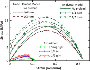
Figure 9 shows that the stress–strain curves obtained by the analytical and the finite element models are in excellent agreement, despite all the simplifications made to derive the analytical solution (the agreement was also verified over a wider range of parameters). However, the experimental stress–strain curves, also shown on Fig. 9, are much lower than these predictions. This indicates that these RVE-based models do not properly capture major phenomena in the actual material.
Comparison of the stress–strain curves of analytical model, finite element model and experiment.

V. FINITE WIDTH MODEL
To refine the model to capture the experiments, several features were added to the model: (i) the free surfaces on the side of the composite were considered; (ii) initial gaps between tablets due to imperfect assembly were included; and (iii) an instability was introduced to induce the “unzipping” phenomenon observed experimentally.
A. Effect of free surfaces
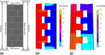
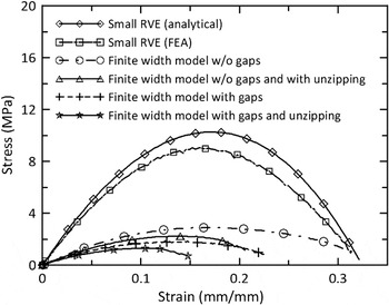
The progressive locking mechanism requires a buildup of transverse stresses (compressive in the overlap region balanced by tensile in the core). This buildup is possible for a periodic RVE, which is assumed to be far enough from free surfaces not to feel their effect (That distance was evaluated to be about 20 tablet thicknesses). In reality, the present model material has only several layers so that the effect of the free surface is likely to be prominent. Therefore, a finite-width finite-element model composed of seven layers was constructed [Fig. 10(a)]. The top and bottom edge were free surfaces, whereas nodes on the left and right edges were constrained to remain on a straight line (using slider elements). Fasteners were modeled with bar elements on the right and left of the model and their extension or contraction was tied to the upper and lower edges of the material [Fig. 10(a)]. The resulting stress–strain curve (Fig. 11) shows stress levels less than a third of the stresses from the small RVE models. The effect of the free surfaces is, therefore, significant; transverse stresses cannot fully develop and the efficacy of the locking mechanisms is greatly diminished.
Finite width model: (a) mesh and boundary conditions; (b) uniform deformation; (c) nonuniform deformation (unzipping).

Comparison of the stress–strain curves of analytical model, finite element model, finite width model with and without gaps and unzipping.

B. Initial gaps
As a second refinement to the model, initial gaps were introduced, following experimental observation and measurements [Fig. 5(a)]. The presence of these gaps further reduces the tensile strength and the strain at failure, as they reduce the contact area between tablets (Fig. 11).
C. “Unzipping”
The “unzipping” effect was clearly observed in the experiment [Fig. 5(d)] and is likely to also affect the stress–strain curves because all the overlap regions within a column do not fail at exactly the same time. To simulate unzipping in the finite width model, a defect was introduced in the model by slightly decreasing the modulus of a few elements in the lower half of the model. The model was then pulled at only two points, located half-way through the thickness. This triggered an “unzipping” type of failure where the overlap areas near the lower surfaces (where defects were introduced) would fail first. The model then progressively opened (“unzipped”) toward the upper side of the model, much like a crack propagating across a material in the direction transverse to loading [Fig. 10(c)]. Incorporating unzipping in the model also had an impact on the stress–stain curves by slightly decreasing the overall strength by about a third and by reducing the strain at failure (Fig. 11).
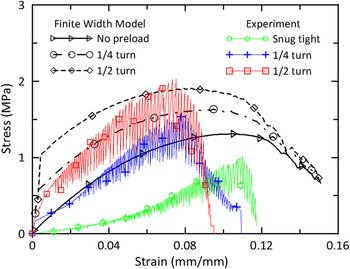
Incorporating the free surfaces, the initial gaps and unzipping brought the stresses close to the experimental values. The results of this refined model are compared with the experiments on Fig. 12 for the three levels of bolt tightening (snug tight, ¼ turn, and ½ turn). The agreement is reasonable, considering the assumptions made in the model and possible imperfections in the material. The tensile strength obtained by the finite width model is reasonably close to the experiments with preloads of 1/4 turn and 1/2 turn, but is ∼30% larger than the experiment under the snug-tight condition. The model properly captures the following effects:
(i) Strain hardening up to a maximum stress followed by softening.
(ii) The initial stress increases as the bolt preload is increased.
(iii) The hardening rate is not dependant on tightening.
(iv) The maximum stress increases as the bolt preload is increased.
(v) The strain at localization decreases as the bolt preload is increased.
Comparison of the stress–strain curves of finite-width model and experiment with different levels of bolt tightening.

The predicted failure strain is ∼50% larger than the experimental value, which was expected since the model has only two columns as opposed to eight in the experiment. Past localization large strains still accumulate, but only in one overlap band in the actual specimen (Fig. 5). The rest of the material does not deform anymore and actually experiences elastic recovery since the overall load decreases, and for this reason the overall strains past localization are smaller in the experiment compared to the model.
VI. CONCLUSIONS
This article presents the first prototype made of PMMA tablets in millimeter size based on the structure of natural nacre, which properly duplicates, for the first time, its unique mechanisms. Progressive tablet locking, strain hardening, and spreading of large deformations over large volumes were all achieved in this new material. The objectives of this model material were to (i) demonstrate how tablet waviness leads to the properties of nacre and (ii) to validate models that can be used in the design of this type of composites. Transverse fasteners act as a strong transverse reinforcement to the composite, which was needed to generate tablet locking. In natural nacre, mineral bridges provide a similar type of reinforcements. The bridges are weak in tension as they are made of minerals. They are, however, nanometers in size, and scaling arguments from fracture mechanics suggest that their strength approaches the theoretical strength of the mineral, estimated at 3.3 GPa.Reference Meyers, Chen, Lin and Seki4 Even though the structure of this PMMA material was not optimized, it still showed strain-hardening behavior and large strain capacity (9–12%). The material is, however, very weak in tension making it not suitable for engineering applications. With the proper mechanical model, this mechanism can, however, be translated to similar composites made of stronger and perhaps smaller tablets (metals and ceramics), and the microstructure can be optimized accordingly to achieve new combinations of strength, modulus, and toughness that may be of interest for engineering applications. The finite element model presented here provides a useful platform to design and optimize similar materials based on the same mechanisms, but using different materials or length scales. Interestingly, experiments on the model material revealed new insights on the mechanics of staggered structures that would have been difficult or impossible to gain from studying natural nacre. The effects of the free boundary, the initial defects, and the “unzipping” are new factors that should be considered in the modeling and design of artificial nacres. This demonstrates the powerful approach of the “model material,” a model that duplicates the key structures of a material at larger scale, and so new mechanisms can be identified.
Finally, comparing natural nacre with this artificial nacre raises some interesting questions on the biomimetics paradigm. Without doubt this material is successful as it duplicates a key mechanism of natural nacre for the first time, yet it only borrows a few of the attributes of natural nacre. Features such as a tough polymer at the interface of small length have been left out. The question is whether these features are required for a successful “artificial nacre” with useful engineering properties. This work suggests that the answer is no, which is consistent with modern biomimetics paradigms. A first critical step in the general process of biomimetics is the abstraction of key structures and mechanism from a selected natural system with attractive properties.Reference Vincent and Mann29, Reference Milwich, Speck, Speck, Stegmaier and Planck30 These key structures can then be implemented into synthetic systems or materials for engineering applications. For example, Velcro uses the key concept of numerous hooks and loops on a surface mimicked from nature. Other than this key feature, natural burrs and Velcro show significant difference in length scale, materials used, and fabrication techniques. The key is that every feature of the natural system does not need to and should not be duplicated in synthetic system. Early flying machines that attempted to copy every feature of bird—including flapping of the wings—led to spectacular failures. This philosophy of biomimetics should also be applied to nacre. This material has a highly sophisticated structure and mechanisms, and this work is an example of how only a few key features were abstracted and translated into a synthetic material.
ACKNOWLEDGMENTS
This work was supported by the Natural Sciences and Engineering Research Council of Canada and the Canada Foundation for Innovation. The CNC machining was performed by Sam Minter from the Mechanical Engineering Department Machine Shop, McGill University. The assembly and mechanical testing were performed with the assistance of Hussein Daou during an undergraduate internship in summer 2009.
APPENDIX: RVE CALCULATIONS
A simplified analytical model was derived to capture the progressive locking of the RVE depicted in Fig. A1.
(a) Periodic RVE of the composite; (b) reduced RVE using symmetry; and (c) RVE deformation under uniaxial stress along the x axis.

A1. Boundary conditions
The RVE of the composite is periodic in the two in-plane directions. Representative volume elements were, therefore, used to capture its mechanics. Figure A1(a) shows an RVE of the material with dimensions. The model will capture uniaxial behavior of the composite, and for this reason the average shear strain was set to zero ( ). Periodic boundary conditions in displacements and tractions are enforced on all sides of the RVE:


The RVE was further reduced using symmetries about the x and y axes, as shown in Fig. A1(b). The associated boundary conditions are


Combining Eqs. (A1), (A2), (A3), and (A4) yields the periodic-symmetric boundary conditions:


These conditions imply that the edges of the RVE can deform, but in doing so they must remain straight and parallel to their initial location. To impose uniaxial tension, a uniform displacement is imposed along the right boundary. The sliding of the tablets is expected to provide the large extensions of the RVE, so that axial strains in the tablets are neglected:

Note that owing to Poisson’s effect and other mechanisms described below, the RVE may expand or contract in the transverse direction.
In the following sections, the mechanics of the RVE is examined in more depth. Stresses and strains are assumed to be uniform in the overlap region of the tablets ( ) and in the core regions (
 ). The balance between these strains and stresses results from interface kinematics, stress transfer at the interface, elasticity of the tablets, and boundary conditions.
A2. Kinematics at the interface
The geometry of the dovetail is such that sliding the tablets may generate expansion in the y direction. This expansion is combined with the strains in the tablets to generate the transverse displacement at the upper edge of the RVE:

and for small θ,

Because of the symmetric-periodic boundary conditions (A6), the expansion along y must be uniform on the upper boundary (y = t) of the RVE, so that

A3. Stress transfer at the interface
The key mechanism for the composite is the load transfer at the interface in the overlap region. Let N and T be the forces normal and tangential to the interface in the overlap region, respectively. They are connected through Coulomb friction by

The x and y components of the contact force can then be written with the small angle approximation as


Combining Eqs. (A7), (A10), and (A11) gives the longitudinal force as function of the transverse force:

In turn, these forces generate stresses in the overlap region:

and

Note that as the tablets slide on one another, the contact area decreases. Note also that Rx induces a tensile (positive) stress along the x direction, whereas Ry induces a compressive (negative) stress along the y direction. Combining the Eqs. (A14), (A15), and (A16) provides

Equation (A17) shows that the tensile stress in the material is provided by a friction term and augmented by a “locking term” proportional to the dovetail angle. The effect of friction is magnified by the dovetail angle through the term f θ at the denominator.
A4. Tablet elasticity
The RVE model is composed of two elastic blocks (modulus E and Poisson’s ratio ν). In this simplified analytical model, the stresses and strains are assumed to be uniform in the core area and in the overlap area (although they might take different values in these two areas). The elasticity in the tablets is governed by Hooke’s law, in-plane stress conditions

and for the overlap area,

A5. Fastener
The tablets are held in place by transverse fasteners (bolts) running through the core regions. Initially the bolt may be tightened by a distance Np, where N is the fraction of turn given to the nut and p is the screw pitch (defined as the axial distance between two consecutive threads). In addition, the bolt will expand or contract according to the transverse deformations of the RVE. The total strain in the bolt is, therefore,  , and the force carried by each bolt is

where At is the tensile area of the bolt, E b is the elastic modulus of the bolt, and ε b is the strain in the bolt.
A6. RVE force balance
Along the x axis, the applied axial stress is simply given by

The axial stress is transmitted in the core region through a thickness t, whereas it is transmitted through the overlap region through a thickness t/2. Therefore, one can write

Along the y axis balancing the forces gives

A7. Result
Equations (A10), (A17), (A18), (A19), (A22), and (A23) form a system of six equations that can be solved for the six unknowns ( ). Of particular interest is the axial stress as a function of the axial strain:

with the nondimensional tablet aspect ratio  overlap ratio
 the nondimensional bolt stiffness
 and the nondimensional bolt tightening
 This result highlights the effect of the structure material parameters on the tensile response of the material.