


I. INTRODUCTION
Material characterization is an important field in microwave engineering and is used in the system design of high-speed circuits to satellite and telemetry applications [Reference Kheir and Hammad1]. Every material has a unique set of electrical characteristics that are dependent on its dielectric properties. Accurate measurements of these properties can provide scientists and engineers with valuable information to properly incorporate the material into its intended application for more materials designs or to monitor a manufacturing process for improved quality control. Several measurement techniques for dielectric properties have been reported in the literature [Reference Kheir and Hammad1–Reference Sheen4] and can be classified into transmission–reflection and resonance techniques. The resonance techniques do not have the swept frequency capability. Unlike resonance techniques, the transmission techniques usually have the sweep frequency ability for the measured frequency range. The transmission and/or reflection signals are always tested to calculate the dielectric properties of the specimen. However, the resonance techniques are more accurate than the transmission techniques, especially in calculating small loss tangent or loss factors, therefore resonance techniques are widely used. In this paper, dielectric constants of liquid- and powder-phase dielectric materials are calculated using the resonance technique using coupled closed and coupled split ring resonators. Closed coupled rings have shown greater sensitivity in comparison with coupled split ring resonator. Results have been validated with simulation and theoretical modeling.
II. DESIGN
Concentric circular resonators were designed on an FR-4 substrate with thickness of the substrate 1.1 mm, and dielectric constant 5.5. Total length and width of the substrate are 84.16 and 41.08 mm, respectively, and are fed through microstrip line capacitively, satisfying the resonant condition

where R is the mean radius of the ring and n is the harmonic order of the resonance. Calculated [Reference Pozar3] mean radius of first, second, and third concentric rings are 15.85, 7.926, and 3.96 mm, respectively, with uniform thickness of 1.77 mm. These concentric ring resonators were capacitively fed through a gap of 0.4108 mm by a microstrip line of length 24.9 mm. Schematic of resonators is shown in Fig. 1. Coupling between the feedline and the ring must be taken into consideration because its capacitive effect can change the resonance frequency significantly [Reference Chang5]. Here the coupling gap between the feed line and ring is represented as a network capacitance C, and ring is represented by a shunt circuit consisting inductance (L r) and capacitance (C r). In the split ring resonators one more network capacitance C is added in the shunt circuit of the ring. Figures 2(a) and 2(b) show the closed coupled and split ring resonators and their equivalent lumped element circuits. C 1 and L 1 represent the capacitance and inductance between the two rings, respectively.
Split and closed coupled ring resonators of the wavelength λ, λ/2, and λ/4 and with the coupling gap 0.41 mm.

(a) Parts (i), (ii), and (iii) show the structures and the equivalent lumped circuits of the 1CRR, 2CRR, and 3CRR, respectively. (b) Parts (i), (ii), and (iii) show the structures and the equivalent lumped circuits of the 1SRR, 2SRR, and 3SRR, respectively.

III. EXPERIMENTAL AND THEORITICAL ANALYSIS
Two materials spirulina platensis-Gietler in semisolid phase and ferrite in powder phase were subjected to characterization for dielectric constants and loss tangent in the L-band. First the frequency response of the Closed Ring Resonator (CRR) and Split Ring Resonator (SRR) without the spirulina platensis-Gietler and ferrite were studied and then followed by the frequency response of the CRR and SRR with spirulina platensis-Gietler and ferrite have been studied. One-millimeter-thin layer of sample was loaded onto the resonators and characterization of the sample was done using shift in resonance.
In the first step complex permittivity and loss tangent of the substrate is calculated. Loaded quality factor Q L is computed using the following relation from the observations:

where f 0 is the resonance frequency, Δf is the 3 dB bandwidth, and Q U is the unloaded quality factor that depends on total insertion loss (IL) of the system and can be estimated using

Total loss of the resonator is inverse of loaded quality factor, which is the sum of losses due to the dielectric component, conducting component, and the losses of the resonator without any external load. Here (1/Q D) is the direct measure of the loss tangent of the materials loaded to the resonator. In the present study, conductor loss is neglected due to very high conductivity of the copper deposited on the substrate:
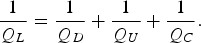
The loss tangent tan δ (substrate) is calculated using the following relation:

where ρ e is the energy filling factor which is the ratio of average energy stored in the specimen to the average energy stored in resonant structure. Loss tangent in equation (5) can be related to the real and imaginary parts of permittivity as follows

where for ɛ′ is the dielectric constant of the substrate of CRR and SRR.
The inaccuracy of the dielectric constant of the substrate does not affect the measurement because the effect of the substrate's dielectric constant gets canceled as shown in

Using equation (5), equation (7) can be rewritten as

where ρ is the energy filling factor of the sample, and ρ 1 and ρ 2 are the energy filling factors of the substrate with the sample and the substrate alone, respectively. Values of the filling factor are chosen empirically on the basis of transmission loss and values of quality factor on loading the resonator with the sample [Reference Krupkay, Derzakowskiz, Riddlex and Baker-Jarvis10].
IV. RESULTS AND DISCUSSION
Figures 3(a)–(c) show the simulated results for spirulina platensis-Gietler (in semisolid phase) and ferrite (in powder phase) using Computer Simulation Technology (CST) microwave studio software for coupled 1, 2, and 3 CRR at 1.5 GHz. Resonance frequency response of the 1CRR of length λ, 2CRR of length λ and λ/2, and 3CRR of length λ, λ/2, and λ/4 with and without spirulina platensis-Gietler (in semisolid phase) and ferrite (in powder phase), as shown in Figs 4(a), 4(b), and 4(c), respectively were taken by the vector network analyzer (ZVA 50 Rohde & Schwartz). Figures 5(a), 5(b), and 5(c) show simulated results in which the shift in frequency response of 1SRR of length λ, 2SRR of length λ and λ/2, and 3SRR of length λ, λ/2, and λ/4 with and without spirulina platensis-Gietler in semisolid phase, respectively. Figures 6(a), 6(b), and 6(c) also show experimental results of the shift in frequency response of 1SRR of length λ, 2SRR of length λ and λ/2, and 3SRR of length λ, λ/2, and λ/4 with and without spirulina platensis-Gietler (in semisolid phase) ferrite (in powder phase), respectively.
Shows the simulated results with CRRs: ____, CRR without any load; _ _, _ _ CRR loaded with ferrite; and - - - - -, CRR loaded with Spirulina.

Shows the experimental results with CRRs: ______, CRR without any load; _ _ _ _ . CRR loaded with ferrite; and - - - - -, CRR loaded with Spirulina.

Shows the simulated results with SRRs: _____, SRR without any load; _ _ _ _, SRR loaded with ferrite; and - - - - -, SRR loaded with Spirulina.

Shows the experimental results with SRRs: ____, SRR without any load; _ _ _ _, SRR loaded with ferrite; and - - - - -, SRR loaded with Spirulina.

Extracted values of effective dielectric constant for spirulina platensis-Gietler and ferrite, from simulation and experiment are given in Table 1. The predicted results for CRR are within ±5% accuracy and the SRR accuracy factor goes up to ±10%. The results clearly show that closed resonators have better accuracy as compared to the split resonator. Higher sensitivity of CRR can also be explained by the lumped element circuits of the ring. The quality factor of the parallel RLC circuit is calculated by the following equation:

where R is the total resistance, C is the total capacitance, L is the total inductance, and Q is the quality factor of the parallel RLC circuit.
C T, L T, and R T are total capacitance, total inductance, and total resistance of the ring, respectively, and Q is the quality factor of the ring. L 1 and C 1 are the mutual inductance and capacitance between the rings, respectively, and L r, L r1, and L r2 are the inductance of the rings of length λ, λ/2, and λ/4 are calculated using their lumped element circuits are given below (from Fig. 2).
The equations above and the equivalent circuit diagram elucidate the reason for higher sensitivity of CRR as compared with SRR. The effective capacitive reactance of the rings increases due to additional gap capacitance resulting in higher losses and poor sensitivity. This could be a reason for lowest sensitivity in 3SRR. Further, from the theoretical model it is clear that due to the presence of split, inductance decreases in SRR as compared to CRR (as shown in Table 2).
Calculated dielectric constant of spirulina platensis-Gietler and ferrite for different types of resonators using experimental and simulation results.

Calculated dielectric constant of spirulina platensis-Gietler and ferrite for different types of resonators using simulation and theoretical model.

Thus, the gap capacitor of SRR plays an important role in deciding the sensitivity. The reported [Reference Jaime6, Reference Dubey, Tyagi, Srivastava, Badola and Jain7] dielectric constant of lithium zinc titanium ferrite and spirulina platensis-Gietler is 15 and 1.9, respectively. Experimentally measured dielectric constant of ferrite and spirulina platensis-Gietler is 14.17–13.68 and 1.76–1.92 with the accuracy of ±5% using closed ring resonator. With SRR values of dielectric constant were found to be in the range 15.1–13.6 for ferrite and 1.74–2.04 for spirulina platensis-Gietler, respectively, with the ±10% accuracy (as shown in Tables 1 and 2). Values of ρ 1 for spirulina platensis-Gietler were 0.014, for ferrite were 0.1, and value of ρ 2 for substrate alone were 0.04, lower value of filling factor in the case of spirulina platensis-Gietler is due to decreases in Q values and in the case of ferrite filling factor is greater than the value of filling factor of substrate due to increase in quality factor because quality factor is a direct measure of energy stored in dielectric material as evident from Table 3. The comparison of accuracy of CRR and SRR with the cavity perturbation [Reference Lobato-Morales, Corona-Chávez, Murthy and Olvera-Cervantes8, Reference Balmus, Pascariu, Creanga, Dumitru and Sandu9] is given in Table 4.
The comparison of the achieved accuracy in the present method with the cavity perturbation methods.

Quality factor of unloaded and loaded CRRs and SRRs.

Results are compared with the ones from theoretical model as shown in Table 2. From the analysis CRRs were found to have more accurate predictability as compared to SRR. Results obtained in this paper were also in agreement with the earlier published results [Reference Jaime6, Reference Dubey, Tyagi, Srivastava, Badola and Jain7].
V. CONCLUSION
This paper presents the comparative study of dielectric characterization of closed and split ring resonator. Two different kinds of samples, viz. ferromagnetic in powder form and bio sample in semi-liquid forms, were taken. The analysis shows that measured values of dielectric parameters using CRR were more accurate than SRR. Experimental results were validated by simulations of the experimental design on the CST microwave studio. The method proposed herein can be used for the dielectric characterization of liquids and solids in powder phase.
 Mahima Kapoor received the B.Sc degree from Dayalbagh Educational Institute Agra India, in 2006, the M.Sc. degree in Pure Physics from the Dayalbagh Educational Institute Agra India, in 2008, and the M.Phil. degree in Electronics from Dayalbagh Educational Institute Agra India, in 2009. Currently, she is working as a Research Scholar with Microwave group, Dayalbagh Educational Institute Agra India. Her current research interests include microwave tuneable devices and EBG structures.
 K. S. Daya did her Ph.D. from Dayalbagh Educational Institute in 2002. From 2002–2003 she did her Post-Doctoral work at Research Center Juelich, Germany. Later joined Center for Applied Research in Electronics, IIT Delhi, India as Project Scientist where her main research interests were MEMS and Photonic crystals. In 2005, she joined Nokia Siemens Networks as RF R&D Scientist working on the development of low-cost and high-gain antenna for standalone mobile network. Since 2007, she is a lecturer at Dayalbagh Educational Institute with her current area of interests being properties of EBG structures, microwave medical bio-sensors, and low-cost RF devices for wireless communication networks.
 G. S. Tyagi did his Ph.D. in 1980 from Birla Institute of Technology & Science Pilani, Rajasthan. He joined Dayalbagh Educational Institute Agra, in 1983 and is currently working as a Professor in the Department of Physics & Computer Science at Dayalbagh Educational Institute, Agra. He has published several research papers in national and international journals. His research interests include magnetically tunable devices and electromagnetic band gap structures at microwave frequencies.



