



Introduction
The oscillator is one of the most essential elements in wireless telecommunication systems. It acts as a fundamental task in extending signal sources for various applications [Reference Zhu, Wang and Wu1]. The microwave oscillators [Reference Anzill, Filleböck and Russer2] possess several parameters including oscillation frequency, phase noise (PN), output power, harmonic suppression, and physical dimension. The PN is one of the most significant factors in increasing signal quality and decreasing error rates. PN improvement is accomplished by different techniques such as increasing the Q-factor of the frequency-selective device in the feedback oscillator [Reference Rohde, Poddar and Böck3, Reference Jin and Tan4].
Dielectric and waveguide filters are high Q-factor 3D structures [Reference Nimehvari Varcheh and Rezaei5–Reference Zhu, Luo, Liao, Daiand and Wu7]. However, they are not convenient for the monolithic microwave integrated circuits (MMICs) and radio frequency integrated circuits (RFICs) structures because of the costly issue and nonplanar profile. Another method is low phase noise (LPN) microwave planar oscillators (MPOs) based on substrate integrate waveguide (SIW) filters [Reference Wang, Zong and Wu8, Reference Nimehvari Varcheh, Rezaei and Kiani9]. These SIW oscillators possess some benefits, the example of which are suitable in mass production, light fabrication cost, compact, easily integrating with common planar circuits, low loss, high Q-factor, and appropriate for MMICs and RFICs configurations [Reference Navaei, Rezaei and Kiani10–Reference Heidari, Rezaei, Kiani and Taherinezhad12]. However, the LPN SIW MPOs are rarely reported in low frequencies.
The other technique for designing LPN MPOs is based on microstrip filters (MFs) [Reference Kiani, Rezaei and Fakhr13–Reference Zhou, Yin, Wang and Wu16], the example of which are microstrip elliptic oscillators [Reference Nimehvari Varcheh and Rezaei17, Reference Nimehvari Varcheh and Rezaei18] and microstrip voltage-controlled oscillators (VCOs) [Reference Li, Tang, Liu, Lu and Cai19]. These microstrip oscillators (MOs) possess some advantages in designing including high Q-factor, mass production, low fabrication cost, miniaturized, and ease-of-integration in MMICs and RFICs structures [Reference Tseng and Huang20–Reference Liu, Xie, Tang and Xiao22]. Also, they are used in low frequency bands [Reference Li, Tang, Lu, Cai, Liu and Luo23, Reference Cai, Liu, Tang and Zhang24]. By employing the MFs as parallel-feedback or series-feedback configurations, the (LPN oscillator) LPNO applications can be realized.
By using fractal geometries, the resonant components could be placed in a small area [Reference Jafari, Naderi, Hatami and Zarrabi25]. The usage of fractal specifications is in frequency-selective surfaces (FSSs) [Reference Yang and Luo26]. FSS applications have been reported in the millimeter filter [Reference Kim, Leite, Park, Kim and Jang27], and antenna [Reference Hua, Li, Wang and Lu28]. Jerusalem is one of the schemes that are used in FSSs [Reference Filho, Silva, Oliveira, Oliveira, Melo, Sousa and Neto29]. This structure is presented in [Reference Kamonsin, Krachodnok, Chomtong and Akkaraekthalin30, Reference Cetin, Kaya, Mertiri, Aslan, Erramilli, Altug and Turkmen31]. In particular, a Jerusalem perspective can be selected in the design of the microwave bandpass filters [Reference Liu, Chen, Xu, Ren, Xu, Ji, Zhao, Zhang and Liu32].
There are many articles about the application of wideband filters in LPNOs [Reference Tseng and Chang33–Reference Cazzorla, Farinelli, Urbani, Cacciamani, Pelliccia, Sorrentino, Giacomozzi and Margesin39]. In [Reference Tseng and Chang33], the LPNO and wideband VCO (WVCO) using microstrip combline filters are investigated. The peak frequency of the Q-factor is selected for oscillator design to obtain a suitable PN performance. This oscillator with the three-pole combline bandpass filter is implemented at 2.05 GHz with a PN of −148 dBc/Hz at 1-MHz offset frequency. Also, by considering varactors in the combline filter, the WVCO is created. This VCO possesses a bandwidth of approximately 54.8% (1.3 to 2.2813 GHz). Over this tuning range, the PN is better than −117 dBc/Hz at 1-MHz offset frequency. In [Reference Rajpoot, Gurjar and Gamad34], the quadrature VCO with LPN and the high tuning range is proposed for radio frequency applications. The PN of this presented VCO is improved by employing the cross-coupled topology. This WVCO possesses a tuning range of about 20% varying from 3.8 to 4.52 GHz. Also, the PN of the structure is nearly −120 dBc/Hz at 1-MHz offset frequency.
In [Reference Jahan, Baichuan, Barakat and Pokharel40], the LPN K-band VCO in 0.18-μm CMOS technology is introduced based on a miniaturized defected ground structure resonator in a coplanar strip line structure. The VCO at 22.07 GHz possesses a PN of −112.31 dBc/Hz at 1-MHz offset frequency. Also, the power of this VCO is 4 mW in a figure of merit (FOM) of −193.2 dB.
In this paper, two X-band MFs are designed, fabricated, and measured. These two MFs are employed in the feedback loop of the planar microwave oscillator as a frequency stabilization component. Thus, two LPN X-band MOs using a BLC have been realized with decent PN performance. The modified Jerusalem MF (MJ-MF) X-band LPNO operates at 8.17 GHz and exhibits a PN of −84, −113, −140, and −161 dBc/Hz at 1-kHz, 10-kHz, 100-kHz, and 1-MHz frequency offset. LPN complementary modified Jerusalem MF (CMJ-MF) X-band oscillator operates at 8.14 GHz and mentions a PN of −76, −105, −136, and −157 dBc/Hz at 1-kHz, 10-kHz, 100-kHz, and 1-MHz frequency offset, respectively.
Theory of the LPN microwave oscillator
In a parallel-feedback MPO, the limitation on the oscillation frequency is expressed by the magnitude and phase response of the open loop circuit.
 \begin{equation}\left| {G\left( {{\omega _0}} \right).H\left( {{\omega _0}} \right)} \right| \gt 1\end{equation}
 \begin{equation}Arg\left[ {G\left( {{\omega _0}} \right). H\left( {{\omega _0}} \right)} \right] = 2n\pi , n \in W\end{equation}
 ${\omega _0}$ mentions the oscillation frequency, G(ω 0) and H(ω 0) define the transfer function of the low noise amplifier (LNA) and frequency-selective part, respectively. In designing, the gain and phase of the loop should be obtained as unit and 360 degrees, respectively. An approximately unique equation for PN performance in microwave parallel-feedback planar oscillator, which is derived by Leeson [Reference Leeson41, Reference Park and Seo42]:
 \begin{equation}{\textrm{PN}}\left( {{f_m}} \right) = {{FKT} \over {2P}}\left[ {1 + {{\left( {{1 \over {2{Q_{\textrm{L}}}}}} \right)}^2}{{\left( {{{{f_0}} \over {{f_m}}}} \right)}^2}} \right],\end{equation}
where F mentions the noise figure (NF) of the transistor, K defines Boltzmann constant, T expresses temperature,  ${f_m}$ emblazons the offset frequency from the carrier, and
 ${f_0}{\ }$ exhibits the oscillation frequency. The P describes the oscillator output power. The Q L determines the loaded Q-factor of the feedback loop resonator, which is derived by [Reference Nallatamby, Prigent, Camiade and Obregon43]
 \begin{equation}{Q_{\textrm{L}}} = {{{\omega _0}} \over 2}\left| {{{{\textrm{d}}\phi \left( {{\omega }} \right)} \over {{\textrm{d}\,\omega }}}} \right|,\end{equation}
where  $\phi \left( \omega \right)$ is the phase function of the open loop parallel-feedback oscillator as an operation of the frequency (ω). By increasing the Q L at the oscillation frequency, the best PN efficiency can be attained.
Microstrip resonator design
Some of the most important objectives in the design of the resonator are low cost, easy fabrication, and miniaturization [Reference Moattari, Bijari and Razavi44, Reference Kiani, Rezaei, Karami and Sadeghzadeh45]. Generally, microstrip resonators possess a light cost and compact structure in comparison with other resonators. According to [Reference Sohrabi, Rezaei, Kiani and Fakhr46], two X-band MFs are designed, fabricated, and measured. The first one is a MJ-MF and the second one is a CMJ-MF. The MJ-MF is a narrowband filter based on the Jerusalem scheme. The CMJ-MF is a wideband filter and complementary of the MJ-MF. These two MFs could be part of this LPN MPOs.
Figure 1 shows the steps of design and S-parameters of the proposed MFs. As shown in Fig. 1(a, b), the narrowband filter is designed in two steps. In the first step, the design of the filter is done by conventional Jerusalem. By considering the S-parameters, it is obvious that the structure does not possess the suitable values of S21 in the frequency range of 5–12.5 GHz. Therefore, in the second step, the S21 has been improved by modifying the initial Jerusalem model. In the following, to achieve a wideband filter based on the proposed narrowband filter design, the complementary narrowband filter is presented. Figure 1(c–e) depicts the three steps of this wideband filter design. Figure 2(a, b) shows the schematic of the MJ-MF and CMJ-MF, respectively. Also, Fig. 2(c, d) depicts the two topologies of MJ-MF and CMJ-MF structures.
The S-parameter results of the MFs design: (a) step one of MJ-MF, (b) step two of MJ-MF, (c) step one of CMJ-MF, (d) step two of CMJ-MF, and (e) step three of CMJ-MF.

The scheme and topology view of the MFs: (a, c) modified Jerusalem and (b, d) complementary modified Jerusalem.

The dimensions of both MJ-MF and CMJ-MF are similar and equal to 42.4 × 28.14 mm2. The operating frequencies of the MJ-MF and CMJ-MF are approximately 8.12 and 8.19 GHz, respectively. Figure 3 illustrates the photographs of these constructed MFs.
The photograph of the constructed prototype X-band MFs: (a, b) modified Jerusalem and (c, d) complementary modified Jerusalem.

The S-parameter (S11 and S21) results of these MFs are shown in Fig. 4. The return loss (RL) and insertion loss (IL) of the MJ-MF and CMJ-MF at the operation frequency are almost −21 and −2.4 dB and −25 and −1.2 dB, respectively.
The results of simulation and measurement for the realized MFs: (a) modified Jerusalem and (b) complementary modified Jerusalem.

Other scattering parameters are not denoted in Fig. 4 in the perspective of the fact which has similar features. The simulation and measurement results are in appropriate agreement. However, because of the manufacturing tolerances, there are slightly negligible shifts in the outcomes.
The group delay of the MJ-MF and CMJ-MF structures at 8.15 GHz frequency is about 1.4 and 0.5 ns, respectively. The better the group delay, the better the PN. Therefore, the PN of the MJ-MF oscillator is better than the PN of the CMJ-MF oscillator. The group delay of MJ-MF and CMJ-MF structures has been shown in Fig. 5(a, b).
The group delay of the MFs: (a) MJ-MF and (b) CMJ-MF.

Table 1 shows a comparison between these two MFs and other researchers’ works. Also, there is an appropriate match between the results of measurement and simulation.
Comparative results between reported and these proposed MFs

* Half-mode SIW.
** Quarter-mode SIW with microstrip line resonators.
LPN X-band MO
The LPN X-band planar free-running oscillator, in this article, consists of different components, the example of which are microwave transistor, X-band MF, LNA, and BLC. The substrate of the MJ-MF oscillator and CMJ-MF oscillator is RT/Duroid 5880 with an  ${\varepsilon _r}$ of 2.2, a loss tangent of 0.0009, and a height of 31 mils. The input and output of the matching networks are 50 Ω.
A low noise pHEMT GaAs FET (a packaged ATF-33143, Avago Technologies) active device is realized as providing the gain of the feedback loop. This microwave active device is biased at 4 V/80 mA. The parameters of NF and 1 dB compression point (P1dB) should be investigated in such a procedure that the minimum quantity of NF (NFmin) and the maximum quantity of P1dB (P1dBmax) are implemented. As a result, the input and output matching networks are presented. This LNA consists of the active device, input, and output match networks and depicts the NF of about 0.92 dB and the P1dB of approximately 6.71 dB.
Generally, the lowest value of a bias transistor causes the NFmin. The NFmin then decreases the PN. However, the NFmin decreases P1dB. Therefore, there is a trade-off between NFmin and P1dBmax [Reference Nimehvari Varcheh, Rezaei and Kiani9]. Eventually, the bias condition of 4 V/80 mA is selected. The most important factor in MPO design is the input/output match network. The parameters of NF and P1dB have to be designed in such a method that the NFmin and the P1dBmax are obtained. Therefore, the input match network has been designed by the input impedance seen from transistor bias to minimize the NF. Furthermore, the output match network has been designed by the output impedance seen from the input matching network to maximize the P1dB [Reference Nimehvari Varcheh, Rezaei and Kiani9]. As a result, the NFmin and maximum gain are achieved 0.92 dB, and 6.7 dB, respectively.
Excessive saturation of the transistor increases the NF and thus increases the PN. As a result, the −10 dB λ/4 directional coupler is used. However, the −10 dB λ/4 directional coupler possesses several disadvantages, the example of which are the possibility of coupling between the amplifier and the −10 dB λ/4 directional coupler, low output power, and high input power damaging the transistor [Reference Nimehvari Varcheh and Rezaei18]. Therefore, the −4 dB BLC is employed instead of the −10 dB λ/4 directional coupler to deliver power to the external load.
Initially, the small signal is figured out and the oscillation condition is attained. Then, the large signal is evaluated to obtain stability oscillation. Finally, the LPN microwave free-running oscillator based on the MF and the BLC is proposed.
Figure 6 depicts the diagram of the design method for the presented LPN MOs, which is mentioned in the following. In the first step, the main parameters are analyzed and the fundamental architecture is specified. In the second step, a suitable frequency stabilization element in the feedback loop of the oscillator is selected. The MF is simulated. In the third step, an appropriate low noise microwave transistor is chosen. The bias and matching network are investigated in this point. In the fourth step, the passive and active circuits are combined. Then, the microwave planar parallel-feedback MO is designed. After that, the small signal is examined to satisfy the criteria on oscillation condition. In the fifth step, the large signal is evaluated to validate the oscillation performance. In the sixth step, the presented LPN MO based on BLC is implemented.
The diagram of the proposed LPN MO.

The configuration of these LPN microwave oscillators based on the MF and the BLC is demonstrated in Fig. 7.
The configuration of the free-running LPN MO: (a) MJ-MF oscillator and (b) CMJ-MF oscillator.

The output spectrum of the MJ-MF oscillator and the CMJ-MF oscillator are shown in Fig. 8(a, b). The MJ-MF oscillator shows the 8.17 GHz output signal with a 21.6 dBm power level. The second harmonic suppression reaches 24 dBc. Also, the CMJ-MF oscillator shows the 8.14 GHz output signal with a 22.2 dBm power level. The second harmonic suppression reaches 27.5 dBc. Figure 9 displays the simulated PN of these schematics.
The output spectrum of the structures: (a) MJ-MF oscillator and (b) CMJ-MF oscillator.

The phase noise simulation of the designed LPNO: (a) MJ-MF oscillator and (b) CMJ-MF oscillator.

As a result, the MJ-MF oscillator illustrates a PN of −84, −113, −140, and −161 dBc/Hz at 1-kHz, 10-kHz, 100-kHz, and 1-MHz frequency offsets, respectively. The CMJ-MF oscillator depicts a PN of −76, −105, −136, and −157 dBc/Hz at 1-kHz, 10-kHz, 100-kHz, and 1-MHz frequency offsets, respectively. The output power of the first harmonic for the MJ-MF oscillator is about 21.6 dB, while the output power of the first harmonic for the CMJ-MF oscillator is nearly 22.2 dB. The MJ-MF oscillator and CMJ-MF oscillator operate at about 8.17 and 8.14 GHz, respectively.
Results and discussion
The total performance of the free-running oscillators should be considered by the FOM parameter. Thus, the FOM of the planar microwave oscillator is expressed by [Reference Choi, Nick and Mortazawi48, Reference Choi, Chen and Mortazawi49]
 \begin{equation}FOM = PN\left( {{f_m}} \right) - 20 log\left( {{{{f_0}} \over {{f_m}}}} \right) + 10 log\left( {{P_{dc}}} \right)\end{equation}
where  $PN\left( {{f_m}} \right){\ }$mentions the PN at the frequency offset
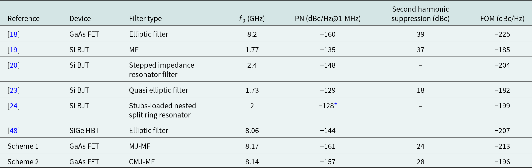
 ${f_m}$, f 0 denotes the oscillation frequency, and P dc is the entire consumed DC power (mW). As a result, the FOMs of the MJ-MF oscillator and CMJ-MF oscillator are −213 dBc/Hz and −196 dBc/Hz, respectively. The function results of these X-band GaAs FET MJ-MF and CMJ-MF oscillators are analyzed with other published microwave microstrip planar oscillators, which are illustrated in Table 2.
Comparative results between published and these presented MOs
* PN at 100-kHz offset frequency.
The influence of narrowband and wideband filters in the desired frequency of the oscillator structure in terms of Q-factor, PN, and FOM is the aim of this paper. In addition to the narrowband filter, the wideband filter has also been investigated in the LPNO application. Therefore, the influence of narrowband and wideband filters in the oscillator structure is checked. Finally, the oscillator based on the narrowband filter possesses a Q-factor of 116, a PN of −161 dBc/Hz at 1-MHz offset frequency, and an FOM of −213 dBc/Hz. However, the oscillator employing the wideband filter possesses the Q-factor of 3, a PN of −157 dBc/Hz at 1-MHz offset frequency, and an FOM of −196 dBc/Hz.
The better the group delay, the better the PN. Also, the better the PN, the better the FOM [Reference Choi, Nick and Mortazawi48]. The group delay of [Reference Nimehvari Varcheh and Rezaei18] is approximately 14 ns, while the group delay of the MJ-MF and CMJ-MF structures are about 1.4 and 0.5 ns, respectively. Therefore, the PN and FOM of [Reference Nimehvari Varcheh and Rezaei18] are better than MJ-MF and CMJ-MF oscillators.
In [Reference Nimehvari Varcheh and Rezaei18], the LPNO based on an elliptic filter and BLC operates at nearly 8.2 GHz. The RT/Duroid 5880 as a substrate and the pHEMT GaAs FET (a packaged ATF-33143, Avago Technologies) are used. This kind of elliptic oscillator shows a PN of −77, −112, −140, and −160 dBc/Hz at 1-kHz, 10-kHz, 100-kHz, and 1-MHz offset frequency and an FOM of −225 dBc/Hz. Also, the second harmonic suppression is about 39 dBc. By changing the active device and selecting SiGe HBT on the same substrate, in [Reference Choi, Nick and Mortazawi48], the LPN elliptic oscillator operates at about 8.06 GHz and shows a PN of −122.5 and −143.5 dBc/Hz at 100-kHz and 1-MHz offset frequency and an FOM of −207 dBc/Hz. The transistor of [Reference Li, Tang, Liu, Lu and Cai19, Reference Tseng and Huang20, Reference Li, Tang, Lu, Cai, Liu and Luo23, Reference Cai, Liu, Tang and Zhang24] is Si BJT. The resonators of them are MF, stepped impedance resonator filter, quasi-elliptic filter, and stubs-loaded nested split ring resonator, respectively. The microstrip and quasi-elliptic filter oscillate in L-band frequency, while the stepped impedance resonator filter and stubs-loaded nested split ring resonator oscillate in S-band frequency. In the category of these Si BJT oscillators, the oscillator based on a stepped impedance resonator filter shows the best PN and FOM. In [Reference Li, Tang, Liu, Lu and Cai19], the structure operates at about 1.77 GHz and shows a PN of −135 dBc/Hz at 1-MHz offset frequency and an FOM of −185 dBc/Hz. Also, the second harmonic suppression is nearly 37 dBc. In [Reference Tseng and Huang20], the structure operates at about 2.4 GHz and mentions a PN of −148 dBc/Hz at 1-MHz offset frequency and an FOM of −204 dBc/Hz. The substrate of this structure is RO4003 (with a dielectric coefficient of 3.38, a thickness of 20 mils, and a loss tangent of 0.0027). In [Reference Li, Tang, Lu, Cai, Liu and Luo23], the structure operates at about 1.73 GHz and depicts a PN of −129 dBc/Hz at 1-MHz offset frequency and an FOM of −182 dBc/Hz. Also, the second harmonic suppression is approximately 18 dBc. Although, in [Reference Cai, Liu, Tang and Zhang24], the structure operates at about 2 GHz and shows a PN of −128 dBc/Hz at 100-kHz offset frequency and an FOM of −199 dBc/Hz. The substrate of this structure is RO4350 (with a dielectric coefficient of 3.66, a thickness of 20 mils, and a loss tangent of 0.0037). The lower the loss tangent, the better the PN [Reference Nimehvari Varcheh and Rezaei18]. Therefore, the PNs of [Reference Tseng and Huang20] and [Reference Cai, Liu, Tang and Zhang24] are not good as Scheme 1 and Scheme 2. The features of active devices of [Reference Li, Tang, Liu, Lu and Cai19] and [Reference Li, Tang, Lu, Cai, Liu and Luo23] are not suitable for X-band oscillator application.
Conclusion
The purpose of this manuscript is based on planar MJ-MF and CMJ-MF and its usage to microwave LPNO. The first filter, MJ-MF, is a narrowband filter based on the Jerusalem scheme. The second one, CMJ-MF, is a wideband filter and complementary of the MJ-MF. The RL and IL of the MJ-MF and CMJ-MF are almost −21 and −2.4 dB and −25 and −1.2 dB, respectively. The low noise ATF-33143 transistor is employed in the LNA as providing the gain of the feedback loop. Finally, two different X-band oscillators based on MFs are realized. The MJ-MF oscillator operates at 8.17 GHz and depicts a PN of −161 dBc/Hz at 1-MHz frequency offset. The CMJ-MF oscillator operates at 8.14 GHz and shows a PN of −157 dBc/Hz at 1-MHz frequency offset.
Acknowledgements
The authors would thank the support from Semnan University. The measurements have been done by Iran Telecommunication Research Centre (ITRC). The authors would thank the ITRC, particularly Akhlaghpasandi and Solat for their cooperation. Also, the authors would like to thank the Editor and reviewers for their constructive comments.
Financial Support
The authors report no funding.
Competing Interests
The authors report no competing interests.
Availability of Data and Materials
There are no supplementary materials and the data is available upon reasonable request.
Author Contributions
Hamed Nimehvari Varcheh has contributed to formal analysis, methodology, conceptualization, software, validation, writing – original draft, and writing – review and editing. Pejman Rezaei has contributed to formal analysis, methodology, validation, supervision, and writing – review and editing. Sina Kiani has contributed to formal analysis, validation, and writing – review and editing.



