1 Introduction
The last decades have seen considerable progress in the conception of micro-electro-mechanical systems. Millimetre-scale tubing is manufactured and assembled in micro-thrusters, used in the stabilisation of satellites in orbit (Chigier & Gemci Reference Chigier and Gemci2003) or in micro-power source for small-scale gas detectors (Srinivasan et al.
Reference Srinivasan, Hsing, Berger, Jensen, Firebaugh, Schmidt, Harold, Lerou and Ryley1997). Micro- and meso-scale combustion are now seen as a potential technology for embedded low-power sources, as reviewed by Ju & Maruta (Reference Ju and Maruta2011), Walther & Ahn (Reference Walther and Ahn2011) and Kaisare & Vlachos (Reference Kaisare and Vlachos2012). The high energy density of hydrocarbon fuels (approximately 60 times larger than that of most efficient lithium-ion electrical batteries) motivates the development of these small- or micro-scale combustion devices (Walther & Ahn Reference Walther and Ahn2011). As evoked by Ju & Maruta (Reference Ju and Maruta2011), several definitions and classifications exist for these systems. Burners of characteristic length below the millimetre scale are usually referred as micro-combustors. Another definition refers to micro-combustion as the combustion occurring below the quenching diameter (Davy Reference Davy1817). Meso-combustors are burners with a characteristic length above the millimetre scale and of the order of the centimetre scale (Fernandez-Pello Reference Fernandez-Pello2002). The device powered may also be used to define the micro-system, as the power source propelling a micro-satellite will be called a micro-propeller, even though its characteristic length does not respect one of the two previous definitions (Yetter et al.
Reference Yetter, Yang, Wu, Wang, Milius, Aksay and Dryer2007). The present study of a laminar premixed flame in a narrow channel (internal width
 $\ell _{i}=5~\text{mm}$
) is thus within the context of meso-combustors.
The invasive presence of the wall, because of the high surface to volume ratio in these systems, accounts for the flame/wall interactions (Ronney Reference Ronney2003). In small-scale combustion, a non-negligible part of the heat transfers are driven by the conduction of heat in the solid wall, while heat transfer through conduction in the fresh gases and radiative heat transfer can play a much smaller role (Boehman Reference Boehman1998). Several studies have addressed the impact of heat loss at the wall in small-scale combustion (Ju & Xu Reference Ju and Xu2005, Reference Ju and Xu2006; Maruta et al. Reference Maruta, Kataoka, Kim, Minaev and Fursenko2005; Li et al. Reference Li, Chou, Yang and Li2009; Veeraragavan & Cadou Reference Veeraragavan and Cadou2011; Gauthier, Watson & Bergthorson Reference Gauthier, Watson and Bergthorson2012; Kurdyumov & Jiménez Reference Kurdyumov and Jiménez2014). In one-dimensional analysis, the heat transfer at the wall may be globalised via a Nusselt number (Ju & Xu Reference Ju and Xu2005; Maruta et al. Reference Maruta, Kataoka, Kim, Minaev and Fursenko2005; Gauthier et al. Reference Gauthier, Watson and Bergthorson2012), which was shown to vary in the vicinity of the flame (Veeraragavan & Cadou Reference Veeraragavan and Cadou2011). In some studies the external surface of the wall is set at the temperature of the fresh mixture (Kurdyumov & Jiménez Reference Kurdyumov and Jiménez2014). The wall thickness is then small compared to the channel height, with a temperature evolution across the solid taken as linear, an hypothesis which may not be always valid in small-scale burners. Few studies have in fact considered the fully coupled problem, with the solving of the heat equation in the solid and accounting for convective heat transfer from the wall exterior surface to the surrounding environment (Norton & Vlachos Reference Norton and Vlachos2003; Ju & Xu Reference Ju and Xu2006; Li et al. Reference Li, Chou, Yang and Li2009).
The early highlight of Davy (Reference Davy1817) and later experimental investigation by Jarosinski (Reference Jarosinski1986) on flame quenching in narrow channels, showed the presence of extinction and the reduction of the flammability range. Two primary wall-quenching mechanisms have been identified. The thermal quenching refers to the heat loss at the burner wall. Below a critical distance, heat loss to the wall overtakes the heat generation from the chemical reactions and quenching of the reaction zone occurs (Lewis & Von Elbe Reference Lewis and Von Elbe1987). The second mechanism is radical quenching, where the diffusion of radicals from the flame to the wall and their recombination at the wall, perturbs the hydrocarbon chain-branching reactions (Kaisare & Vlachos Reference Kaisare and Vlachos2012). Dealing with an active surface, the catching of H radicals by the wall surface impacts on the overall radical pool and subsequently on the wall temperature distribution (Xie et al. Reference Xie, Yang, Zhang and Liu2015). Besides, this surface reaction is enhanced by high wall temperature, promoting strong radical quenching. For lower temperature, H radicals recombine in the gas phase, their concentration is then reduced close to the wall and thermal quenching becomes the dominant flame inhibitor (Ju & Xu Reference Ju and Xu2006). Theoretical analysis by Bai et al. (Reference Bai, Chen, Zhang and Chen2013) and experiments by Miesse et al. (Reference Miesse, Masel, Jensen, Shannon and Short2004) pointed out that the relative occurrence of the thermal, versus the radical quenching, does not vary much with the burner characteristic size, making it not specific to small-scale combustion devices. Notice that quartz walls under atmospheric pressure, feature negligible radical quenching (Kizaki et al. Reference Kizaki, Nakamura, Tezuka, Hasegawa and Maruta2015).
Concerning the coupling with flow dynamics, the pioneering work of Karlovitz et al. (Reference Karlovitz, Denniston, Knapschaefer and Wells1953) showed the importance of the sheared flow/flame interactions in combustion. This is especially true in the case of small-scale burners where the flame is placed exclusively within boundary layers (Kim & Maruta Reference Kim and Maruta2006). The sheared flows in these highly confined configurations are very sensitive to density variations, making the thermal expansion an additional key ingredient of the problem (Short & Kessler Reference Short and Kessler2009).
Stabilising a flame in a channel or a tube by adjusting the mass flow rate of fresh gases, is experimentally (Kim et al. Reference Kim, Kataoka, Maruyama and Maruta2005) and numerically (Kim & Maruta Reference Kim and Maruta2006) challenging, mainly because of the difference in characteristic time scales between convection, heat transfers and combustion. To overcome this difficulty, stabilisation is sometimes secured by imposing a temperature profile in the wall boundary condition (Maruta et al. Reference Maruta, Kataoka, Kim, Minaev and Fursenko2005; Gauthier et al. Reference Gauthier, Watson and Bergthorson2012; Sánchez-Sanz, Fernández-Galisteo & Kurdyumov Reference Sánchez-Sanz, Fernández-Galisteo and Kurdyumov2014). Various other options have been discussed in the literature without adding thermal forcing at the wall. The flame front has also been tracked in a well-defined reference frame attached to the flame, thus limiting the length of the computational domain (Chakraborty, Mukhopadhyay & Sen Reference Chakraborty, Mukhopadhyay and Sen2008; Jiménez, Fernández-Galisteo & Kurdyumov Reference Jiménez, Fernández-Galisteo and Kurdyumov2015). A given radial position and temperature level (i.e. a temperature known to be attained within the flame) is then used as the origin of the reference frame (Kurdyumov & Fernandez-Tarrazo Reference Kurdyumov and Fernandez-Tarrazo2002; Kurdyumov Reference Kurdyumov2011; Kurdyumov & Jiménez Reference Kurdyumov and Jiménez2014). Flames stabilised near the channel entrance by heat transfer at the wall have also been studied (Norton & Vlachos Reference Norton and Vlachos2003; Li et al. Reference Li, Chou, Yang and Li2009). In the present study, the flame freely propagating in the channel is stabilised by the incoming mass flow rate, which exactly matches the overall mass burning rate.
Because of the numerous couplings between chemistry, heat transfer and flame propagation in flame–wall interaction (Poinsot, Haworth & Bruneaux Reference Poinsot, Haworth and Bruneaux1993; Ganter et al. Reference Ganter, Heinrich, Meier, Kuenne, Jainski, Rissmann, Dreizler and Janicka2017), the complexity level of the chemistry introduced in the simulation of small-scale combustion is usually in line with the physical phenomena under study. Focusing on a wide parametric analysis, global single- or multi-step chemical schemes have been used (Norton & Vlachos Reference Norton and Vlachos2003; Ju & Xu Reference Ju and Xu2006; Kim & Maruta Reference Kim and Maruta2006; Tsai Reference Tsai2008; Bianco, Chibbaro & Legros Reference Bianco, Chibbaro and Legros2015), or skeletal mechanism for methane–air mixtures (Li et al. Reference Li, Chou, Yang and Li2009; Gauthier et al. Reference Gauthier, Watson and Bergthorson2012). The simulation of combustion instabilities in small-scale systems may require a refined description of chemistry (Nakamura et al. Reference Nakamura, Fan, Minaev, Sereshchenko, Fursenko, Tsuboi and Maruta2012). Hydrogen–air flames have been simulated with detailed schemes (Pizza et al. Reference Pizza, Frouzakis, Mantzaras, Tomboulides and Boulouchos2010), also to examine the impact of the Soret effect (Jiménez et al. Reference Jiménez, Fernández-Galisteo and Kurdyumov2015). In the case of methane–air, Kizaki et al. (Reference Kizaki, Nakamura, Tezuka, Hasegawa and Maruta2015) reported two-dimensional simulations in a low Mach number formalism with the detailed GRI-3.0 mechanism (Smith et al. Reference Smith, Golden, Frenklach, Moriarty, Eiteneer, Goldenberg, Bowman, Hanson, Song, Gardiner, Lissianski and Qin1999), with good agreement against experiments on a quenched flame stabilised after imposing a temperature profile.
Stoichiometric laminar premixed flame propagating in a quartz channel. Energy release and temperature in the solid. Flow from left to right. GRI-1.2 chemical mechanism.

Under adiabatic conditions and with a tube diameter, or a channel height, below the millimetre scale, a stretched flame surface can hardly develop and the problem is reduced to a single direction (Gauthier et al. Reference Gauthier, Watson and Bergthorson2012; Bai et al. Reference Bai, Chen, Zhang and Chen2013). Heat losses with wall quenching (Gauthier et al. Reference Gauthier, Watson and Bergthorson2012) impose at least two-dimensional simulations, as does larger channel height, because of the flow redirection by the flame (Kim & Maruta Reference Kim and Maruta2006). It is common to consider the problem as symmetrical, either with respect to the middle plane in a channel or to the centreline in a tube. Indeed, close to unity Lewis number steady flames have always been found to be symmetric (Kurdyumov & Jiménez Reference Kurdyumov and Jiménez2014; Gauthier & Bergthorson Reference Gauthier and Bergthorson2016), except for diameters exceeding a hundred times the characteristic flame thickness (Tsai Reference Tsai2008). For Lewis numbers larger than unity, vibratory instability of the planar flame in the tube can develop (Clavin, Pelcé & He Reference Clavin, Pelcé and He1990). For Lewis numbers lower than unity, the coexistence of symmetrical and non-symmetrical flames has been discussed by Jiménez et al. (Reference Jiménez, Fernández-Galisteo and Kurdyumov2015), making the Lewis number a key ingredient of symmetry breaking. Few studies have performed three-dimensional simulations of flames in tubes, thereby accounting for azimuthal effects (Kurdyumov & Fernandez-Tarrazo Reference Kurdyumov and Fernandez-Tarrazo2002; Tsai Reference Tsai2008; Pizza et al. Reference Pizza, Frouzakis, Mantzaras, Tomboulides and Boulouchos2010). In the case of a diverging tube diameter, so-called spinning flame instabilities were shown to appear (Xu & Ju Reference Xu and Ju2007). Another specific unsteady phenomenon called flame repetitive extinction ignition (FREI) was also observed by Maruta et al. (Reference Maruta, Kataoka, Kim, Minaev and Fursenko2005) and Richecoeur & Kyritsis (Reference Richecoeur and Kyritsis2005), and simulated by Bucci, Robinet & Chibbaro (Reference Bucci, Robinet and Chibbaro2016) with single-step chemistry and with an imposed external source of heat at the wall.
Aside from flames in canonical tubes or channels, some studies considered more practical small-scale burner configurations. Ronney (Reference Ronney2003) performed an analysis of a U-shaped reactor, with the products preheating the reactants. Ju & Choi (Reference Ju and Choi2003) analysed two flames propagating in opposite directions in parallel channels, to study the excess of enthalpy effect in small-scale combustion. Kim et al. (Reference Kim, Aizumi, Yokomori, Kato, Fujimori and Maruta2007) studied experimentally and analytically the swiss-roll burner configuration, while Kuo & Ronney (Reference Kuo and Ronney2007) developed a two-dimensional numerical model of a similar spiral configuration.
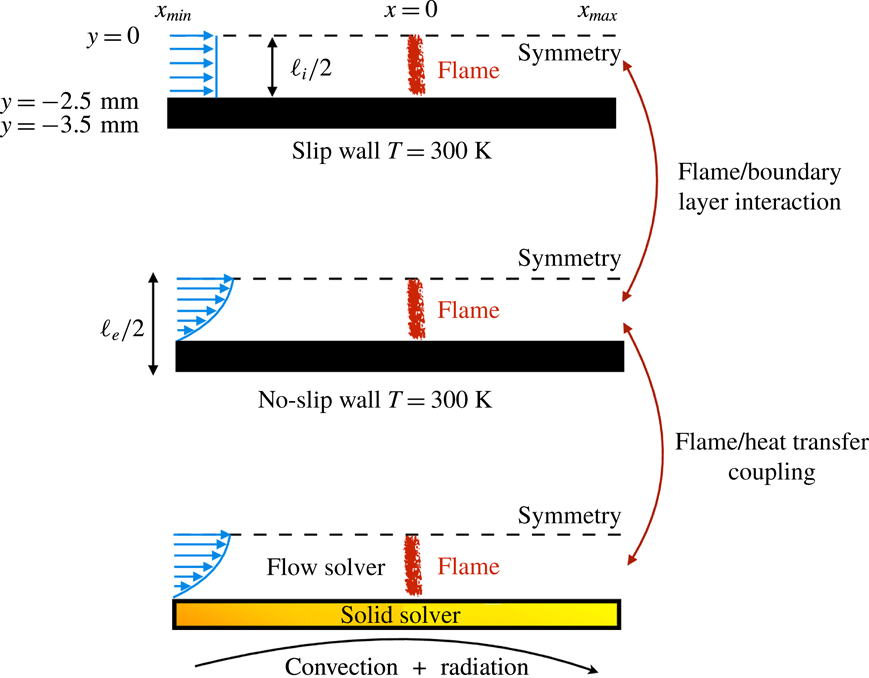
The objective of the present work is to build up on these previous studies with a specific focus on the response of the flame shape to wall heat-transfer properties. A numerical simulation database of stoichiometric methane–air flames propagating in a narrow channel is analysed (figure 1). These flames, stabilised in a channel by an incoming flow, have been obtained for various wall boundary conditions with a fully compressible Navier–Stokes flow solver coupled to a solid heat-transfer solver. Complex chemistry, GRI-1.2 (Frenklach et al. Reference Frenklach, Wang, Yu, Goldenberg, Bowman, Hanson, Davidson, Chang, Smith, Golden, Gardiner and Lissianski1995) and a skeleton mechanism (appendix A), and complex transport properties are used (Curtiss & Hirschfelder Reference Curtiss and Hirschfelder1949). In the subsequent section, the problem configuration is first discussed along with the numerical procedure and the tools introduced to probe the reacting flow. A preliminary analysis of a scaling law for the burning velocity is conducted, versus the reference stoichiometric planar flame speed, the flame surface and the amount of heat loss at the wall. Then, the coupling phenomena between the heat exchanged between the flame and the wall, the heat transfer within the wall and its environment and the variable density sheared flow, are the objects of the subsequent sections. To isolate the various effects at play, three simulations are examined (figure 2): a flame propagating in a channel with a slip wall at 300 K; a no-slip wall at 300 K and finally a quartz wall with solid heat transfer coupled to the flow. This allows for isolating the flame/boundary layer interaction from the flame/wall heat-transfer coupling. The impact of the wall heat-transfer properties is then further examined and the results collected in a diagram that delineates between the flame regimes observed in the simulations. The analysis of the chemical schemes used and the numerical approach developed to reach a stable flame, are both reported in appendixes.
Cases simulated. Internal channel height:
 $\ell _{i}=5~\text{mm}$
. External channel height:
 $\ell _{e}=7~\text{mm}$
.

2 Flow configuration and numerics
A two-dimensional flame stabilised in a planar channel, of internal height
 $\ell _{i}=5~\text{mm}$
and of external height
 $\ell _{e}=7~\text{mm}$
, with 1 mm thick walls made of quartz, is considered. Because of the close to unity Lewis number of the methane/air mixture and the dimensions of the channel (Kurdyumov & Jiménez Reference Kurdyumov and Jiménez2014), the problem is supposed symmetrical with respect to the longitudinal mid-plane
 $y=0~\text{mm}$
(figure 2). A stoichiometric mixture of methane–air at the ambient air temperature
 $T_{o}=300$
K and atmospheric pressure, flows in a laminar regime from the left into the channel at the mass flow rate
 $\dot{Q}_{m}$
, with the bulk velocity
 $S_{L}=\dot{Q}_{m}/(\unicode[STIX]{x1D70C}_{o}A)$
, where
 $\unicode[STIX]{x1D70C}_{o}$
is the density of the fresh gases and
 $A=(\ell _{i}/2)\times 1$
is the channel half-section (‘
 $\times 1$
’ denotes the third direction, in which the problem is assumed uniform).
Both the origin
 $x=0~\text{mm}$
of the axial and streamwise coordinate taken at the flame position and the burnt gases far right coordinate
 $x_{max}=15~\text{mm}$
are fixed. On the other hand, the inlet boundary at the left of the domain,
 $x_{min}$
varies with the configuration. For the isothermal wall at
 $T_{o}$
,
 $x_{min}=-7~\text{mm}$
is sufficient to ensure a zero-velocity gradient in the streamwise direction at the inlet. In the configuration where the thermal coupling between the wall and the fluid is fully accounted for,
 $x_{min}=-51~\text{mm}$
is necessary to carefully capture the upstream heat diffusion through the wall and the preheating of the reactants. Depending on the configuration (slip or no-slip wall, see figure 2), a flat or a Poiseuille velocity profile is imposed at the inlet. Two mesh resolutions have been used,
 $\unicode[STIX]{x1D6FF}_{x}=12.5~\unicode[STIX]{x03BC}\text{m}$
for the detailed chemistry (1 M mesh cells) and
 $\unicode[STIX]{x1D6FF}_{x}=25~\unicode[STIX]{x03BC}\text{m}$
for the skeleton chemical scheme (256 k mesh cells). A regular mesh composed of squares of
 $\unicode[STIX]{x1D6FF}_{x}$
on a side is used from the inlet (
 $x_{min}$
) up to
 $x=9~\text{mm}$
, from where the mesh is progressively coarsened in the
 $x$
direction up to the outlet (
 $x_{max}$
), with a geometric coefficient of
 $1.0025$
. The resolution in the spanwise
 $y$
direction stays fixed
 $\unicode[STIX]{x1D6FF}_{y}=\unicode[STIX]{x1D6FF}_{x}$
.
The conservation equations of mass, momentum (without gravity force) and total sensible energy are solved in their fully compressible form over the structured mesh in a finite volume formulation resorting to a fourth-order skew–symmetric-like scheme for the convective fluxes (Ducros et al. Reference Ducros, Ferrand, Nicoud, Weber, Darracq, Gacherieu and Poinsot1999) and to a fourth-order centred scheme for the viscous and diffusive fluxes. The equations solved in the gas read
 $$\begin{eqnarray}\displaystyle & \displaystyle \frac{\unicode[STIX]{x2202}\unicode[STIX]{x1D70C}Y_{k}}{\unicode[STIX]{x2202}t}+\frac{\unicode[STIX]{x2202}}{\unicode[STIX]{x2202}x_{j}}(\unicode[STIX]{x1D70C}(u_{j}+V_{j}^{k})Y_{k})=\dot{\unicode[STIX]{x1D714}}_{k}, & \displaystyle\end{eqnarray}$$
 $$\begin{eqnarray}\displaystyle & \displaystyle \frac{\unicode[STIX]{x2202}\unicode[STIX]{x1D70C}u_{i}}{\unicode[STIX]{x2202}t}+\frac{\unicode[STIX]{x2202}}{\unicode[STIX]{x2202}x_{j}}(\unicode[STIX]{x1D70C}u_{j}u_{i})=-\frac{\unicode[STIX]{x2202}P}{\unicode[STIX]{x2202}x_{i}}+\frac{\unicode[STIX]{x2202}\unicode[STIX]{x1D70F}_{ij}}{\unicode[STIX]{x2202}x_{j}}, & \displaystyle\end{eqnarray}$$
 $$\begin{eqnarray}\displaystyle \frac{\unicode[STIX]{x2202}\unicode[STIX]{x1D70C}e_{T}^{s}}{\unicode[STIX]{x2202}t}+\frac{\unicode[STIX]{x2202}}{\unicode[STIX]{x2202}x_{j}}(\unicode[STIX]{x1D70C}u_{j}e_{T}^{s}) & = & \displaystyle -\frac{\unicode[STIX]{x2202}Pu_{i}}{\unicode[STIX]{x2202}x_{i}}+\frac{\unicode[STIX]{x2202}\unicode[STIX]{x1D70F}_{ij}u_{j}}{\unicode[STIX]{x2202}x_{i}}+\frac{\unicode[STIX]{x2202}}{\unicode[STIX]{x2202}x_{j}}\left(\unicode[STIX]{x1D706}\frac{\unicode[STIX]{x2202}T}{\unicode[STIX]{x2202}x_{j}}-\mathop{\sum }_{k=1}^{N}\unicode[STIX]{x1D70C}V_{j}^{k}h_{k}^{s}Y_{k}\right)\nonumber\\ \displaystyle & & \displaystyle -\,\mathop{\sum }_{k=1}^{N}h_{k}^{o}\dot{\unicode[STIX]{x1D714}}_{k},\end{eqnarray}$$
where
 $\unicode[STIX]{x1D70C}$
denotes the density,
 $Y_{k}$
is the
 $k$
th species mass fraction,
 $T$
is the temperature and
 $P$
is the pressure;
 $u_{i}$
are the components of the velocity vector,
 $V_{j}^{k}$
is the molecular diffusion velocity of the
 $k$
th species in the
 $j$
th direction,
 $\dot{\unicode[STIX]{x1D714}}_{k}$
the chemical source and
 $\unicode[STIX]{x1D70F}_{ij}$
is the Newtonian viscous tensor (Emanuel Reference Emanuel1994). Values of
 $V_{j}^{k}$
, the viscosity and
 $\unicode[STIX]{x1D706}$
, the thermal conductivity, are computed for the multicomponent gas following Curtiss & Hirschfelder (Reference Curtiss and Hirschfelder1949), with a correction velocity to secure mass conservation (Giovangigli Reference Giovangigli1999). Viscosities and thermal conductivities are obtained with a third-order fitting procedure (Kee, Rupley & Miller Reference Kee, Rupley and Miller1989). The Soret effect is not accounted for. In (2.3),
 $h_{k}^{s}$
is the sensible enthalpy and
 $h_{k}^{o}$
is the enthalpy of formation of the
 $k$
th species (Giovangigli Reference Giovangigli1999),
 $e_{T}^{s}$
denotes the total sensible or non-chemical energy,
 $$\begin{eqnarray}\unicode[STIX]{x1D70C}e_{T}^{s}=\frac{1}{2}\unicode[STIX]{x1D70C}\boldsymbol{u}\boldsymbol{\cdot }\boldsymbol{u}+\mathop{\sum }_{k=1}^{N}\unicode[STIX]{x1D70C}Y_{k}\left(\int _{T_{o}}^{T}C_{V_{k}}(T^{+})\,\text{d}T^{+}-\frac{R}{W_{k}}T_{o}\right),\end{eqnarray}$$
with
 $C_{V_{k}}$
the calorific capacities. The ideal-gas equation of state provides the pressure
 $$\begin{eqnarray}P=\unicode[STIX]{x1D70C}RT\mathop{\sum }_{k=1}^{N}\frac{Y_{k}}{W_{k}},\end{eqnarray}$$
where
 $R=8.3144621~\text{J}~\text{mol}^{-1}~\text{K}^{-1}$
is the ideal-gas constant and
 $W_{k}$
the molecular weight of the
 $k$
th species (
 $k=1,\ldots ,N$
).
In the solid, the heat-transfer equation is solved
 $$\begin{eqnarray}\unicode[STIX]{x1D70C}_{s}C_{s}\frac{\unicode[STIX]{x2202}T_{s}}{\unicode[STIX]{x2202}t}=\frac{\unicode[STIX]{x2202}}{\unicode[STIX]{x2202}x_{j}}\left(\unicode[STIX]{x1D706}_{s}\frac{\unicode[STIX]{x2202}T_{s}}{\unicode[STIX]{x2202}x_{j}}\right),\end{eqnarray}$$
where
 $\unicode[STIX]{x1D70C}_{s}$
is the density,
 $C_{s}(T_{s})$
is the heat capacity and
 $\unicode[STIX]{x1D706}_{s}(T_{s})$
is the thermal conductivity. The wall thermal properties are those of fused quartz, accounting for the variation with temperature of thermal conductivity and heat capacity (Momentive 2017), with a fixed value of the density in the solid
 $\unicode[STIX]{x1D70C}_{s}=2200~\text{kg}~\text{m}^{-3}$
. In the base case, the exterior wall surface at the computed temperature
 $T_{w_{e}}$
exchanges energy with the surrounding air at the fixed temperature
 $T_{o}=300~\text{K}$
with a global convective heat transfer coefficient
 $h_{o}=30~\text{W}~\text{m}^{-2}~\text{K}^{-1}$
, which is at the upper limit for natural convection. The value of this coefficient and of the thermal conductivity in the wall are varied in the second part of the study. Radiative heat loss of the solid external surface to the ambient air is accounted for through a grey body hypothesis, with an emission coefficient
 $\unicode[STIX]{x1D700}(T)$
decaying linearly from 0.95 at 290 K to 0.75 at 1800 K. Therefore, over the wall outer surface in contact with ambient air, the boundary condition reads
 $\boldsymbol{n}_{e}\boldsymbol{\cdot }(-\unicode[STIX]{x1D706}_{s}\unicode[STIX]{x1D735}T_{s})=h_{o}(T_{w_{e}}-T_{o})+\unicode[STIX]{x1D700}\unicode[STIX]{x1D70E}(T_{w_{e}}^{4}-T_{o}^{4})$
, with
 $\unicode[STIX]{x1D70E}=5.670373\times 10^{-8}~\text{W}~\text{m}^{-2}~\text{K}^{-4}$
the Stefan–Boltzmann constant. The boundary condition at the wall surface inside the channel expresses the continuity of the thermal flux,
 $\boldsymbol{n}_{i}\boldsymbol{\cdot }(-\unicode[STIX]{x1D706}\unicode[STIX]{x1D735}T)=\boldsymbol{n}_{i}\boldsymbol{\cdot }(-\unicode[STIX]{x1D706}_{s}\unicode[STIX]{x1D735}T_{s})$
, where
 $\boldsymbol{n}_{i}$
is the normal vector to the inner wall. The length of the channel is large enough so that on approaching the extremities of the wall, the thermal fluxes in both directions become independent of the position. At the inlet, the temperature is 300 K and at the outlet, the temperature distribution over the wall is computed to match the uniform fluxes of heat inside the wall extremity, i.e. the temperature gradient at the extremity equals the one of the first neighbouring cell.
Time is advanced with a fourth-order Runge–Kutta scheme. One-dimensional Navier–Stokes characteristic boundary conditions (NSCBC) are applied to the gas phase (Poinsot & Lele Reference Poinsot and Lele1992). The skew–symmetric centred scheme is non-dissipative and it is completed by an addition of second- and fourth-order artificial dissipation terms (Jameson, Schmidt & Turkel Reference Jameson, Schmidt and Turkel1981; Swanson & Turkel Reference Swanson and Turkel1992; Tatsumi, Martinelli & Jameson Reference Tatsumi, Martinelli and Jameson1995), which are set here to minimum contributions to avoid perturbing the molecular diffusive transport of chemical species within the internal flame structure (see appendix A). The additional numerical convective flux is controlled by four parameters
 $\unicode[STIX]{x1D6FC}_{1}$
,
 $\unicode[STIX]{x1D6FC}_{2}$
,
 $\unicode[STIX]{x1D6FD}_{1}$
and
 $\unicode[STIX]{x1D6FD}_{2}$
. The coefficients
 $\unicode[STIX]{x1D6FC}_{1}=0.5$
and
 $\unicode[STIX]{x1D6FC}_{2}=0.5$
are for the second-order terms,
 $\unicode[STIX]{x1D6FD}_{1}=0.06$
and
 $\unicode[STIX]{x1D6FD}_{2}=1$
for the fourth-order contribution (Tatsumi et al.
Reference Tatsumi, Martinelli and Jameson1995). This combination of numerical methods in the SiTCom-B flow solver used in this study has been reported previously as a good compromise in terms of computational efficiency and accuracy for the simulation of laminar and direct numerical simulation (DNS) of turbulent reactive flows (Domingo, Vervisch & Veynante Reference Domingo, Vervisch and Veynante2008; Lodato, Vervisch & Domingo Reference Lodato, Vervisch and Domingo2009; Subramanian, Domingo & Vervisch Reference Subramanian, Domingo and Vervisch2010; Lodier et al.
Reference Lodier, Merlin, Domingo, Vervisch and Ravet2012; Merlin, Domingo & Vervisch Reference Merlin, Domingo and Vervisch2013; Petit et al.
Reference Petit, Ribert, Lartigue and Domingo2013; Bouheraoua, Domingo & Ribert Reference Bouheraoua, Domingo and Ribert2017; Domingo & Vervisch Reference Domingo and Vervisch2017). The flow solver is coupled at the wall with an alternate direction implicit Douglas–Gunn solution of the equation of heat in the solid (Douglas Reference Douglas1955). In (2.6), the divergence of the flux of heat inside the wall is decomposed according to
 $\unicode[STIX]{x1D735}\boldsymbol{\cdot }(\unicode[STIX]{x1D706}_{s}(T_{s})\unicode[STIX]{x1D735}T_{s})=\unicode[STIX]{x1D706}_{s}(T_{s})\unicode[STIX]{x1D6FB}^{2}T_{s}+\unicode[STIX]{x1D735}\unicode[STIX]{x1D706}_{s}(T_{s})\boldsymbol{\cdot }\unicode[STIX]{x1D735}T_{s}$
, in which the second-order derivative is treated implicitly and the cross-product term is added to the remaining part of the Douglas–Gunn algorithm. The implementation follows the high-performance parallel computing strategy discussed by Duchaine et al. (Reference Duchaine, Corpron, Pons, Moureau, Nicoud and Poinsot2009). Based on the large difference in characteristic time scales in the solid and the flow, a de-synchronisation method is applied to secure a fast convergence toward the steady state solutions (Koren Reference Koren2016). The effective accuracy of the coupled discretisation schemes (fourth order in the flow, second order in the wall) together with boundary conditions, can reach at the very best second order. Also, because of the prohibitive cost required for conducting multiple simulations with the present numerical setting, progressively increasing the resolution, it is technically not possible to fully conclude on the degree of mesh convergence, as was done in Kagan & Sivashinsky (Reference Kagan and Sivashinsky2010) in the study of the transition from deflagration to detonation in narrow tubes simulated with a single-step chemistry. Instead, here we need to rely on the resolution assessment of the flame chemical structure reported in appendix A.
A reference simulation was first performed with the detailed GRI-1.2 methane/air chemical scheme (figure 1), involving 32 species and 177 elementary reactions (Frenklach et al. Reference Frenklach, Wang, Yu, Goldenberg, Bowman, Hanson, Davidson, Chang, Smith, Golden, Gardiner and Lissianski1995). The results are compared in appendix A against those obtained with a skeleton chemical mechanism developed with an automated approach for kinetics reduction and optimisation of the chemical rates under given conditions (Jaouen, Vervisch & Domingo Reference Jaouen, Vervisch and Domingo2017a ; Jaouen et al. Reference Jaouen, Vervisch, Domingo and Ribert2017b ). Both in a one-dimensional flame subjected to heat loss and in the simulation of a flame in the channel, the behaviour of the skeletal mechanism stays close to the detailed one, motivating the coming study (see appendix A). In this reduced scheme, 15 species react over 26 elementary reactions, thus reducing the computational time significantly and allowing us to perform the parametric study. The level of complexity of the present skeleton mechanism is similar to the scheme by Smooke & Giovangigli (Reference Smooke and Giovangigli1991) (16 species and 25 reactions) validated against experimental data by Ganter et al. (Reference Ganter, Heinrich, Meier, Kuenne, Jainski, Rissmann, Dreizler and Janicka2017).
The freely propagating adiabatic flame speed taken as reference for normalisation of the results is
 $S_{L}^{o}=0.3803~\text{m}~\text{s}^{-1}$
, the corresponding adiabatic flame temperature is
 $T_{f}^{o}=2231~\text{K}$
, the thermal flame thickness based on the temperature gradient is
 $\unicode[STIX]{x1D6FF}_{f}^{o}=451~\unicode[STIX]{x03BC}\text{m}$
and the peak of heat release rate is
 $\dot{\unicode[STIX]{x1D714}}_{\unicode[STIX]{x1D70C}E}^{o}=4.10~\text{GW}~\text{m}^{-3}$
. Approaching the cold wall, the flame surface will be considered quenched when the local heat release rate is an order of magnitude below
 $\dot{\unicode[STIX]{x1D714}}_{\unicode[STIX]{x1D70C}E}^{o}$
, the value at which the relative displacement speed of the front vanishes.
The flame stabilised in the narrow channel is obtained starting from a preliminary simulation of a one-dimensional freely propagating and adiabatic stoichiometric premixed flame. This flame solution is applied to the two-dimensional domain, first imposing the flame temperature profile in the wall. Then, the temperature in the wall is relaxed progressively to
 $T_{o}=300~\text{K}$
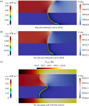
, to reach the first case of a slip and isothermal wall (figures 2 and 3
a). From this converged solution, the no slip and isothermal wall case is addressed by modifying both the inlet profile and the wall boundary condition (figure 3
b). Finally, the last case is obtained coupling the flow solver with the solution of heat transfer at and within the wall (figure 3
c). Most small-scale burners rely on anchored flames rather than moving ones and having stable flames exchanging heat with the wall is more likely in practice (Vican et al.
Reference Vican, Gajdeczko, Dryer, Milius, Aksay and Yetter2002; Weinberg et al.
Reference Weinberg, Rowe, Min and Ronney2002). The objective is thus to exactly match the flow rate with the flame burning rate in order to control the flame location. Also, for each of these converged solutions, the flame is freely stabilised in the channel by the incoming flow, after applying a specific transient procedure based on a pseudo-Galilean transformation (see appendix B). Notice that due to the large heat capacities of solids, the heat wave in the solid propagates upstream at a much slower speed than the flame. In case the mass flow rate would be significantly below the overall flame burning rate, the reaction zone would therefore propagate upstream over a wall at 300 K. An upstream-flame movement actually corresponds to a flame propagating over an isothermal wall (figure 3
b). The flame moving downstream in the channel is not considered here because, in a real small-scale combustion devices, it would correspond to flame blow off due to lack of proper system calibration, an issue which is outside of the scope of this study.
Above symmetry axis: pressure. Below symmetry axis: heat release source term. Black lines: iso-
 $c=0.7$
. Vector: flame front normal toward fresh gases. Flow from left to right. Zoom in the flame zone.

Flame properties. Quartz wall: heat conductive wall.

Flame parameters.
 $T_{f}$
: maximum temperature in the burnt gases.
 $\unicode[STIX]{x1D6FF}_{f}$
: thermal flame thickness.
 $\unicode[STIX]{x1D6F4}_{f}$
: flame length.
 $k_{w}$
: wall heat-transfer coefficient inside the channel.
 $S_{L}$
: flame speed.
 $S_{L}^{o}$
: adiabatic flame speed.
 $\unicode[STIX]{x0394}S_{L}$
: Departure between
 $S_{L}$
by (3.1) and by simulation.

3 Analysis of the burning velocity
The flame burning velocity
 $S_{L}$
is defined as the bulk velocity computed from the mass flow rate in the channel (table 1). As referred to above, the adiabatic methane–air flame propagates at
 $S_{L}^{o}=0.3803~\text{m}~\text{s}^{-1}$
with the reduced chemical mechanism. The slip wall at 300 K leads to
 $S_{L}=0.4670~\text{m}~\text{s}^{-1}>S_{L}^{o}$
, the no-slip wall at 300 K to
 $S_{L}=0.3640~\text{m}~\text{s}^{-1}<S_{L}^{o}$
and the no-slip wall with heat transfer
 $S_{L}=0.4655~\text{m}~\text{s}^{-1}>S_{L}^{o}$
(figure 3). Therefore, the flame speed increases with edge-flame quenching at an isothermal cold and slip wall, decreases with the introduction of the boundary layer, to increase again with heat-transfer coupling within the wall.
In all cases, heat loss at the wall quenches the flame. Moving along the flame surface from its peak value on the centreline to the quenched zone, with isothermal walls the heat release source term decreases first exponentially to then follows an almost linear decay, before a drop toward quenching (figure 4
a). The maximum heat release rate located at the axis of symmetry differs from the reference adiabatic one, it reaches 94 % of
 $\dot{\unicode[STIX]{x1D714}}_{\unicode[STIX]{x1D70C}E}^{o}$
in the case of an isothermal slip wall, 96 % with an isothermal no-slip wall and 129 % for a wall with heat transfer. In the latter, the heat release first decays linearly from the axis, before a rapid decrease followed by a response similar to the isothermal wall cases.
As previously discussed in the literature (Gonzalez, Borghi & Saouab Reference Gonzalez, Borghi and Saouab1992; Michaelis & Rogg Reference Michaelis and Rogg2004), the shape taken by the flame strongly depends on the wall boundary conditions (figure 3). The slip and isothermal wall promotes a shape convex toward the fresh gases and the boundary layer flattens the flame along the axis, as observed by Kim & Maruta (Reference Kim and Maruta2006). The heat transferred in the wall fastens the reaction zone at the wall so that the flame front recedes on the axis of symmetry. The flame becomes concave toward the fresh gases close to the axis, a topological change which was already discussed by Norton & Vlachos (Reference Norton and Vlachos2003) and Li et al. (Reference Li, Chou, Yang and Li2009) in the case of a flame anchored near the inlet of a small-scale combustion device.
The flame length is measured following the peak heat release rate along the curve front and is denoted
 $\unicode[STIX]{x1D6F4}_{f}$
. In the case of an adiabatic wall (not shown), the one-dimensional flame is actually recovered with
 $\unicode[STIX]{x1D6F4}_{f}^{o}=\ell _{i}/2=2.5~\text{mm}$
, the distance between the axis and the channel walls. With a slip wall at 300 K, the lengthening of the flame gives
 $\unicode[STIX]{x1D6F4}_{f}/\unicode[STIX]{x1D6F4}_{f}^{o}=1.50$
(table 1). The increase in burning velocity is
 $S_{L}/S_{L}^{o}=1.23$
, hence smaller than
 $\unicode[STIX]{x1D6F4}_{f}/\unicode[STIX]{x1D6F4}_{f}^{o}$
because of the decay of the burning rate when approaching flame quenching at the wall (figure 4
a). The no-slip condition at 300 K gives
 $\unicode[STIX]{x1D6F4}_{f}/\unicode[STIX]{x1D6F4}_{f}^{o}=1.20$
for
 $S_{L}/S_{L}^{o}=0.96$
. The addition of heat transfer in the wall leads to
 $S_{L}/S_{L}^{o}=1.22$
with
 $\unicode[STIX]{x1D6F4}_{f}/\unicode[STIX]{x1D6F4}_{f}^{o}=1.32$
. The flame lengthening effect may be added to the planar flame analysis of Kazakov (Reference Kazakov2012), expressing the effect of heat loss, at first order, with a linear damping factor:
 $$\begin{eqnarray}\frac{S_{L}}{S_{L}^{o}}=\frac{\unicode[STIX]{x1D6F4}_{f}}{\unicode[STIX]{x1D6F4}_{f}^{o}}\left(1-\frac{k_{w}}{(\dot{Q}_{m}/A)C_{P,o}}\right),\end{eqnarray}$$
where
 $k_{w}=\dot{q}_{w}/\unicode[STIX]{x0394}\overline{T}~(\text{W}~\text{m}^{-2}~\text{K}^{-1})$
is a heat transfer coefficient, with
 $\dot{q}_{w}~(\text{W}~\text{m}^{-2})$
defined as a positive heat flux at the wall downstream of the flame, for a gain in fluid internal energy between the two channel sections located at the streamwise positions
 $x_{1}$
and
 $x_{max}$
,
 $$\begin{eqnarray}\dot{q}_{w}=-\frac{1}{x_{max}-x_{1}}\int _{x_{1}}^{x_{max}}\left(\unicode[STIX]{x1D706}_{f}\frac{\unicode[STIX]{x2202}T}{\unicode[STIX]{x2202}y}\right)_{y=-\ell _{i}/2}\,\text{d}x,\end{eqnarray}$$
 $\unicode[STIX]{x1D706}_{f}$
is the thermal conductivity of the fluid and
 $\unicode[STIX]{x0394}\overline{T}$
is computed from temperatures averaged between the two channel sections in the gas and in the solid
 $$\begin{eqnarray}\unicode[STIX]{x0394}\overline{T}=\frac{1}{(x_{max}-x_{1})}\int _{x_{1}}^{x_{max}}\left(\underbrace{\frac{1}{(\ell _{e}-\ell _{i})/2}\int _{-\ell _{e}/2}^{-\ell _{i}/2}T(x,y)\,\text{d}y}_{solid}-\overbrace{\frac{1}{\ell _{i}/2}\int _{-\ell _{i}/2}^{0}T(x,y)\,\text{d}y}^{gas}\right)\,\text{d}x.\end{eqnarray}$$
The integration domain is defined starting at
 $x_{1}$
, in the burnt gases at the most downstream position reached by the curved flame surface, to extend in the streamwise direction up to
 $x_{max}$
, the end of the computational domain. The transfer coefficient
 $k_{w}=\dot{q}_{w}/\unicode[STIX]{x0394}\overline{T}$
varies significantly with the type of boundary condition at the wall. The highest level,
 $k_{w}=112~\text{W}~\text{m}^{-2}~\text{K}^{-1}$
(
 $\dot{q}_{w}=145~\text{kW}~\text{m}^{-2}$
,
 $\unicode[STIX]{x0394}\overline{T}=1300~\text{K}$
), is for the isothermal slip wall, which is the most efficient to cool the edge flame approaching the wall. The value of
 $k_{w}$
decreases to
 $87~\text{W}~\text{m}^{-2}~\text{K}^{-1}$
(
 $\dot{q}_{w}=102~\text{kW}~\text{m}^{-2}$
,
 $\unicode[STIX]{x0394}\overline{T}=1170~\text{K}$
) with the development of the boundary layer along the isothermal wall and further down to
 $59~\text{W}~\text{m}^{-2}~\text{K}^{-1}$
(
 $\dot{q}_{w}=38~\text{kW}~\text{m}^{-2}$
,
 $\unicode[STIX]{x0394}\overline{T}=644~\text{K}$
) with the heat conductive wall.
For the two isothermal cases, the departure between
 $S_{L}$
measured in the simulation and the relation (3.1) stays below 2.5 % (table 1). The departure attains 3.4 % for the quartz wall case, exhibiting a lower theoretical flame speed than the flame speed observed in the simulation. This departure is due to the preheating of the reactants, not considered by the scaling low, and which increases the flame velocity. This applicability to the simulation of the combination of a global budget with a scaling law for the flame speed, comforts our confidence in the relevance of the numerical framework, which will be assessed further in the following through additional budgets.
4 Isothermal channel wall
The isothermal slip and no-slip configurations are first examined to revisit the interaction between the boundary layer and the flame in the narrow channel. The first observation concerns the temperature field, the adiabatic flame temperature is never reached because of the thermal influence of the cold wall up to the centre of the channel. The departure to the adiabatic flame temperature is more pronounced in the no-slip-wall case (figure 4 b).
The local flame displacement speed decreases when approaching the isothermal wall, following the lowering of the burning rate due to heat loss (figure 4
a). The velocity difference between the flow and the flame is reduced by the boundary layer and the flame is flattened in the no-slip-wall case compared to the slip-wall case, as observed in figures 3 and 5. The development of the thermal boundary layer also benefits from the rising of the fluid particle residence time in the no-slip-wall case, favouring in return the rate of heat losses at the edge flame close to the wall. In consequence, the maximum temperature is lowered (figure 4
b) and the flame quenches
 $69~\unicode[STIX]{x03BC}\text{m}$
away from the no-slip wall, while it almost touches the slip wall (figure 5).
Flame shape defined from the maximum heat release rate (symmetry axis:
 $y=0$
, wall:
 $y=-2.5~\text{mm}$
).

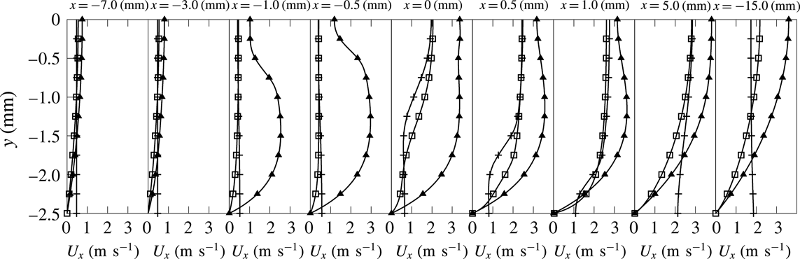
Spanwise (
 $y$
) distributions of streamwise velocity component at various
 $x$
locations. Line with pluses: isothermal slip wall. Line with squares: isothermal no-slip wall. Line with triangles: quartz heat conductive wall.

Spanwise distributions of streamwise velocity component at various
 $x$
locations upstream of the flame (symmetry axis:
 $y=0$
, wall:
 $y=-2.5~\text{mm}$
).

The velocity profiles progressively evolve from the fresh to the burnt gas side of the channel according to the flame shape (figure 6). In the slip-wall case, the velocity increases at the wall when approaching the flame (figure 7
a), to recover an almost flat profile in the burnt gases (line with plus symbols in figure 6). In the no-slip case, the transfer of momentum in the wall-normal direction is visible up to the axis, with a reduction of the velocity peaks (figure 8). In both cases, the flow acceleration on the axis at the flame location is larger than in the adiabatic case (figure 8). The confinement without the boundary layer (slip wall) leads for
 $x>25\unicode[STIX]{x1D6FF}_{f}$
in figure 8(a) to a flow that is even faster close to the wall, whereas the viscous layer preserves the expected hierarchy in the velocity distribution, with a continuous acceleration when proceeding toward the axis (figure 8
b). In the case of a heat conductive wall, the picture is different and this will be discussed in a separate section (line with triangles in figure 6).
Streamwise velocity component versus
 $x$
position at various
 $y$
locations.

Figures 8(c) and 8(d) are streamwise velocity profiles close to the flame front. On the axis, the longitudinal velocity component drops before the flame to a minimum value equal to 0.99
 $S_{L}^{o}$
and 1.07
 $S_{L}^{o}$
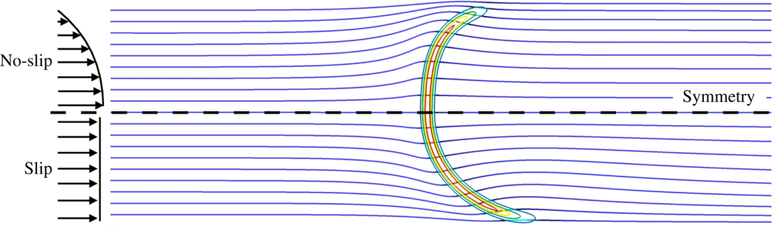
, in the slip and no-slip cases, respectively. Moving away from the axis, as in any curved reaction zone (Clavin Reference Clavin1994; Clavin & Searby Reference Clavin and Searby2016), the component of the velocity in the direction normal to the front benefits from gas expansion, while the tangential velocity component is left unchanged. The gas expansion produced by the heat release thus deviates the streamlines in the flame normal direction, causing their convergence toward the axis right after the reaction zone (figure 9). Mass conservation in these low Mach number flows implies a corresponding divergence of the streamlines upstream of the flame. This flow topology may be put in line with the overall increase of the flame surface promoting the flame acceleration discussed in the relation (3.1).
The influence of the wall sheared flow is also visible through intermediate chemical species. An intensified recombination of the H and HO
 $_{2}$
radicals is observed with the no-slip wall, as seen comparing for the radical H the lines with circles (
 $y=-2.2~\text{mm}$
) in figure 10(a,b), and for HO
 $_{2}$
the lines with open triangles (
 $y=-2.5~\text{mm}$
) in figure 10(c,d). The mass fraction of hydrogen is reduced by a factor of two with the viscous wall, following the lower temperature levels (not shown for brevity) observed in the presence of the boundary layer. The reduction of the overall spreading of the reaction zones in the streamwise direction from slip the to no-slip wall is also visible in these figures, through the narrowing of the profiles of H and HO
 $_{2}$
, in direct relation with the change in flame shape (figure 9).
Isothermal slip and no-slip configurations are compared taking advantage of the symmetry. Streamlines and flame with contours of 20, 40, 60 and 80 % of
 $\max (\dot{\unicode[STIX]{x1D714}}_{\unicode[STIX]{x1D70C}E})$
.

Streamwise distribution of species mass fractions at various spanwise
 $y$
locations.

Temperature distribution in the quartz wall versus
 $x$
position for various
 $y$
locations.
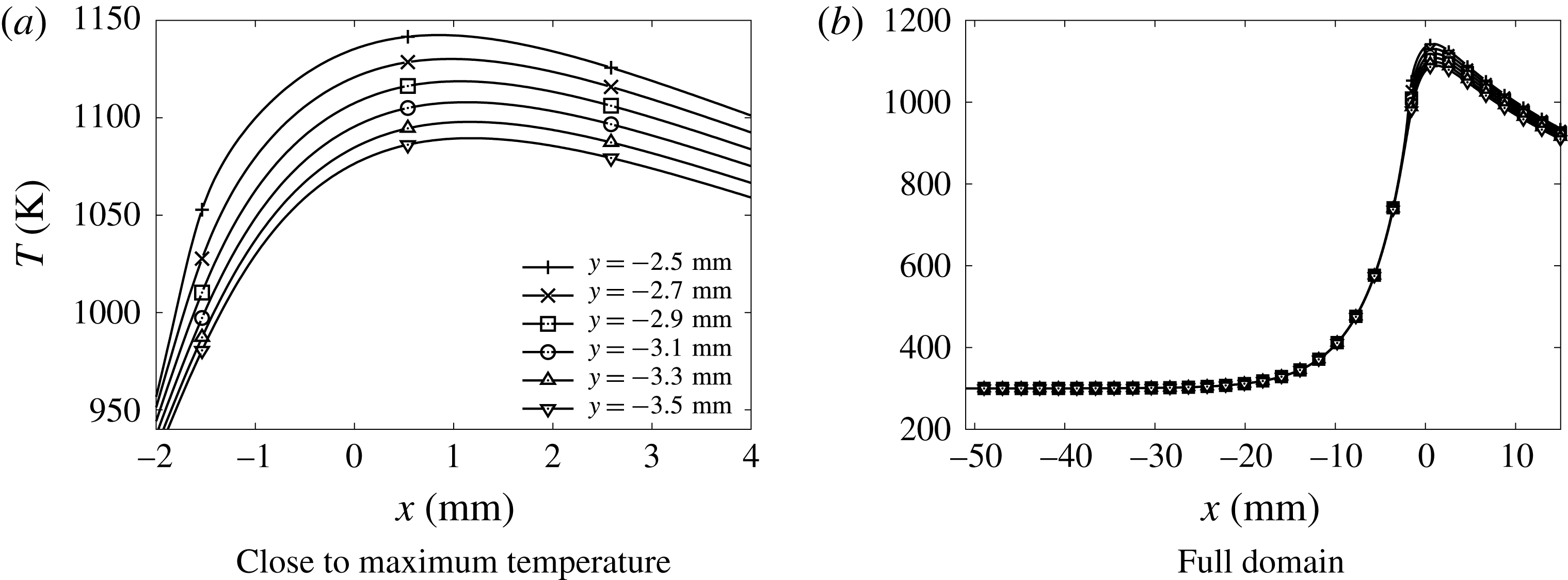
Temperature distributions in the gas at various
 $x$
and
 $y$
positions. Heat conductive wall case.

5 Heat conductive wall
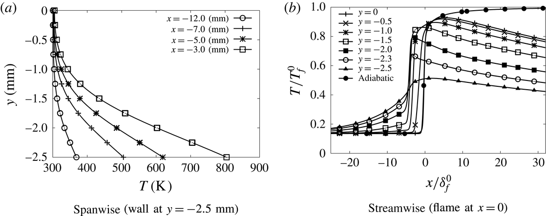
Temperatures much higher than 300 K are observed in the wall heated by the flame (figure 11). In the gas, the temperature gradient in the wall-normal direction drops significantly, also upstream of the flame (figure 12
a). Consequently, the heat flux at the wall decreases by a factor 1.5 compared to the isothermal no-slip case (table 1), making the edge of the flame close to the wall much more robust. The temperature distribution inside the wall is non-uniform in the transverse direction (figure 11). Thus a fully multi-dimensional temperature field can be expected for a quartz channel under the present dimensions. Considering the strong influence of the wall temperature on the flame behaviour, the variation of more than 50 K, which is observed in figure 11, can hardly be neglected, as it would be in the hypothesis of a one-dimensional wall featuring heat transfer in the longitudinal direction only. In this direction, the heat diffuses inside the quartz wall well upstream of the flame location, over a length of the order of
 $20~\text{mm}\approx 45\unicode[STIX]{x1D6FF}_{f}^{o}$
(figure 11
b). This promotes the development of a thermal boundary layer upstream of the flame, which spreads over more than half of the computational domain in the direction normal to the wall (figure 12
a). The fresh gases flowing close to the wall are therefore now preheated before entering the reaction zone (figure 12
b). This preheating effect does not reach the centreline of the channel. Nevertheless, because of the reduction of the heat flux at the wall, the decay of the temperature in the burnt gases along the centreline is reduced compared to the isothermal wall condition (see figure 4
b for
 $x>20\unicode[STIX]{x1D6FF}_{f}^{o}$
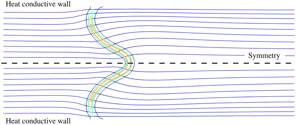
). These heat transfers provoke a drastic change in the shape of the flame (figures 5 and 13). The edge flame propagates faster close to the wall and the flame surface features an inflection point. The flame shape, which is inverted compared to the isothermal case, has its trailing part now on the axis of symmetry (figure 13). The flame which was convex toward the fresh gases on the centreline (so-called mushroom flame) with the isothermal wall condition, becomes concave (tulip flame). As expected in concave flame fronts (Choi & Puri Reference Choi and Puri2003), the burning rate is enhanced in the curved flame close to the centreline (figure 4
a). In addition, because of the reduction in heat flux at the wall, the burning rate stays above that of the two isothermal cases up to a length of 2.6 mm over the flame surface, and always above the burning rate of the no-slip isothermal case (figure 4
a).
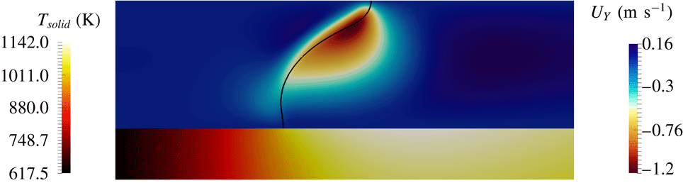
Near the axis of symmetry upstream of the reaction zone, the flame shape implies deviation of the streamlines toward the centre of the channel (figure 13). As discussed above, the fluid is mainly accelerated in the normal direction to the local flame surface, which is now not aligned with the centreline, leading to an increase of the transverse velocity component toward the wall (figure 14). This induces a decay of the streamwise velocity right after its first peak (figure 15). Upstream of the flame, at
 $x_{fg}=-15\unicode[STIX]{x1D6FF}_{f}^{o}$
, this centreline velocity is
 $1.98S_{L}^{o}$
, while the bulk flame velocity with the heat conductive wall is
 $1.22S_{L}^{o}$
(table 1), thus with a centreline velocity of
 $1.22\times (3/2)S_{L}^{o}=1.83S_{L}^{o}$
in the inlet Poiseuille flow. This slight acceleration well before the flame, from
 $1.83S_{L}^{o}$
to
 $1.98S_{L}^{o}$
, results from the flow dilatation within the thermal boundary layer. An acceleration which is in fact visible in figure 15 for
 $x/\unicode[STIX]{x1D6FF}_{f}^{o}\in [-15,-7]$
(see also line with triangle in figure 6), through the positive slope in the axial velocity before the strong velocity jump across the reaction zone. Hence, the coupling with wall heat transfer modifies dramatically the landscape, through a profound re-organisation of the variable density flow and the propagating flame. This combination of the heat loss reduction at the edge flame close to the wall and in the burnt gases, with the preheating of the fresh gases by heat conduction in the wall, results in a burning velocity 28 % larger than in the no-slip isothermal case (table 1).
Quartz heat conductive wall (symmetric view). Streamlines and flame with contours of 10, 30, 50 and 70 % of
 $\max (\dot{\unicode[STIX]{x1D714}}_{\unicode[STIX]{x1D70C}E})$
.

To further examine the acceleration upstream of the flame in the numerical simulation, the enthalpy budget between the channel inlet at
 $x=x_{min}$
(
 $\unicode[STIX]{x1D70C}_{o}$
,
 $T_{o}$
,
 $C_{P,o}$
and
 $S_{L}=\dot{Q}_{m}/(\unicode[STIX]{x1D70C}_{o}A)$
) and the position
 $x_{fg}=-15\unicode[STIX]{x1D6FF}_{f}^{o}$
upstream of the flame as previously defined, may be written
 $$\begin{eqnarray}\unicode[STIX]{x1D70C}_{o}S_{L}\unicode[STIX]{x1D6F4}_{f}^{o}C_{P,o}T_{o}-\int _{-\ell _{i}/2}^{0}[\unicode[STIX]{x1D70C}uC_{P}T](x_{fg},y)\,\text{d}y+\dot{\unicode[STIX]{x1D719}}(x_{fg})+\dot{q}_{w}^{o}=0,\end{eqnarray}$$
where
 $\unicode[STIX]{x1D6F4}_{f}^{o}=\ell _{i}/2$
is the adiabatic flame length as above and
 $\dot{q}_{w}^{o}$
and
 $\dot{\unicode[STIX]{x1D719}}(x_{fg})$
are, respectively, the diffusive heat flux at the wall and across a channel section just before the flame
 $$\begin{eqnarray}\displaystyle & \displaystyle \dot{q}_{w}^{o}=-\!\int _{x_{min}}^{x_{fg}}\left[\unicode[STIX]{x1D706}_{f}\frac{\unicode[STIX]{x2202}T(x,-\ell _{i}/2)}{\unicode[STIX]{x2202}y}\right]\,\text{d}x, & \displaystyle\end{eqnarray}$$
 $$\begin{eqnarray}\displaystyle & \displaystyle \dot{\unicode[STIX]{x1D719}}(x_{fg})=\int _{-\ell _{i}/2}^{0}\left[\unicode[STIX]{x1D706}_{f}\frac{\unicode[STIX]{x2202}T(x_{fg},y)}{\unicode[STIX]{x2202}x}\right]\,\text{d}y. & \displaystyle\end{eqnarray}$$
The relation (5.1) may be re-organised in
 $$\begin{eqnarray}\displaystyle & \displaystyle \dot{q}_{w}^{o}=u^{+}(x_{fg})\int _{-\ell _{i}/2}^{0}[\unicode[STIX]{x1D70C}C_{P}T](x_{fg},y)\,\text{d}y-\unicode[STIX]{x1D70C}_{o}S_{L}\unicode[STIX]{x1D6F4}_{f}^{o}C_{P,o}T_{o}-\dot{\unicode[STIX]{x1D719}}(x_{fg}), & \displaystyle\end{eqnarray}$$
 $$\begin{eqnarray}\displaystyle & \displaystyle \dot{q}_{w}^{o}=T^{+}(x_{fg})\int _{-\ell _{i}/2}^{0}[\unicode[STIX]{x1D70C}uC_{P}](x_{fg},y)\,\text{d}y-\unicode[STIX]{x1D70C}_{o}S_{L}\unicode[STIX]{x1D6F4}_{f}^{o}C_{P,o}T_{o}-\dot{\unicode[STIX]{x1D719}}(x_{fg}), & \displaystyle\end{eqnarray}$$
with
 $u^{+}(x)$
and
 $T^{+}(x)$
defined as the spanwise weighted averages of velocity and temperature,
 $$\begin{eqnarray}\int _{-\ell _{i}/2}^{0}[\unicode[STIX]{x1D70C}uC_{P}T](x,y)\,\text{d}y=u^{+}(x)\int _{-\ell _{i}/2}^{0}[\unicode[STIX]{x1D70C}C_{P}T](x,y)\,\text{d}y=T^{+}(x)\int _{-\ell _{i}/2}^{0}[\unicode[STIX]{x1D70C}uC_{P}](x,y)\,\text{d}y.\end{eqnarray}$$
In the simulation, the relation
 $(3/2)u^{+}(x_{fg})=1.98S_{L}$
is verified as in a Poiseuille flow, where 1.98
 $S_{L}$
is the accelerated centreline velocity discussed above, suggesting that
 $u^{+}$
behaves as an equivalent Poiseuille channel flow bulk velocity. Further, assuming a low Mach number flow with a constant background pressure in the fresh gases,
 $\unicode[STIX]{x1D70C}_{o}T_{o}=\unicode[STIX]{x1D70C}T$
and a constant heat capacity,
 $C_{P}=C_{P,o}$
, the relations (5.4) and (5.5) become (with
 $\unicode[STIX]{x1D6F4}_{f}^{o}=\ell _{i}/2$
)
 $$\begin{eqnarray}\frac{u^{+}(x_{fg})-S_{L}}{S_{L}}=\frac{T^{+}-T_{o}}{T_{o}}=\frac{\dot{q}_{w}^{o}+\dot{\unicode[STIX]{x1D719}}(x_{fg})}{\unicode[STIX]{x1D70C}_{o}S_{L}\unicode[STIX]{x1D6F4}_{f}^{o}C_{P,o}T_{o}}.\end{eqnarray}$$
Top: transverse (spanwise) fluid velocity component (black line: iso-
 $c=0.7$
). Bottom: temperature distribution in the quartz wall.

Streamwise velocity component along the axis of symmetry.

The equations (5.7) and (3.1) may be combined to express the coupling between heat transfer and the flow velocity upstream of the flame
 $$\begin{eqnarray}u^{+}(x_{fg})=S_{L}^{o}\left(\frac{\unicode[STIX]{x1D6F4}_{f}}{\unicode[STIX]{x1D6F4}_{f}^{o}}\overbrace{\left(1-\frac{k_{w}}{(\dot{Q}_{m}/A)C_{P,o}}\right)}^{(\text{i})}+\underbrace{\frac{\dot{q}_{w}^{o}+\dot{\unicode[STIX]{x1D719}}(x_{fg})}{\unicode[STIX]{x1D70C}_{o}S_{L}^{o}\unicode[STIX]{x1D6F4}_{f}^{o}C_{P,o}T_{o}}}_{(\text{ii})}\right).\end{eqnarray}$$
The term (i) represents the heat extracted from the flame by the wall in the zone of the burnt gases, while the term (ii) informs on the heat that is transferred to the fresh gases by the wall (
 $\dot{q}_{w}^{o}$
) and by the flame (
 $\dot{\unicode[STIX]{x1D719}}(x_{fg})$
). The conductive flux in the wall connects these heat transfers, leading to the observed fluid acceleration upstream of the reactive front. The relative variations of the normalised velocity and temperature of the relation (5.7) differ by only 0.95 % in the simulation, with
 $u^{+}$
and
 $T^{+}$
computed from the relation (5.6). This confirms the almost isobaric behaviour of the heated flow of fresh gases upstream of the flame and the convergence of the coupled fluid/solid simulation. Most of this departure actually comes from the variation of
 $C_{P}$
, whose average over the channel sections evolves by 1.5 % between the inlet and
 $x_{fg}$
.
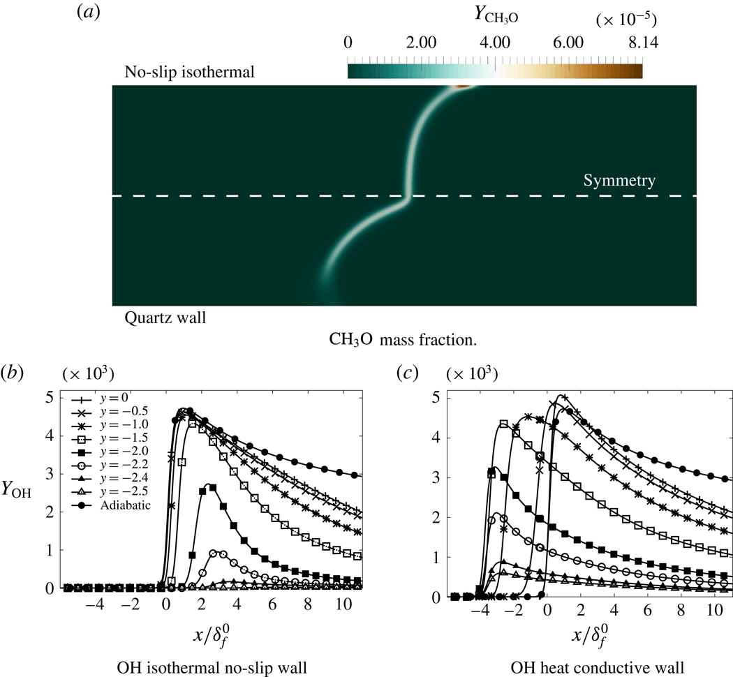
Distributions of
 $\text{CH}_{3}\text{O}$
in the flame zone and streamwise OH profiles at various distances from the axis.

The response of the low temperature chemistry observed in the simulations close to wall can easily be questioned in terms of the reliability of the detail of the chemical kinetics, but some global behaviour may be underlined. Intermediate hydrocarbon radicals, such as
 $\text{CH}_{3}\text{O}$
, which accumulates close to a cold wall, completely vanish in the presence of a hot conductive wall (figure 16
a). Similarly, the increased temperature close to the wall promotes OH concentrations higher than in the isothermal case (compare figures 16
b and 16
c). This relates to temperature levels which are large enough in the conductive wall case to trigger the reactions with high activation energies controlling the OH radical production, whereas the reactions consuming OH are activated in all cases because they depend on much lower activation energies (see table 2).
Units are mol, s,
 $\text{cm}^{3}$
, cal and K. Reduced
 $\text{CH}_{4}$
/air scheme for the stoichiometric condition. The Chaperon efficiencies of the GRI-1.2 mechanism are preserved for both three-body and fall-off reactions.

6 Discussion and conclusion: flame response to wall heat transfer properties in a regime diagram
The results discussed above have been obtained with either an isothermal wall or a heat conductive wall made of quartz. The channel is also submitted to an outside convective flux representative of natural convection. Important differences have been observed between these wall thermal conditions, both in terms of flame shape and burning velocity. The conductivity of heat in the wall
 $\unicode[STIX]{x1D706}$
and
 $h_{o}$
, the convective heat-transfer coefficient with the surrounding air, are now varied. Fifteen simulations have been performed varying the ratio
 $\unicode[STIX]{x1D706}/\unicode[STIX]{x1D706}_{quartz}$
between 0.2 and 50. This ratio is applied to the conductivity of quartz (Momentive 2017), in order to mimic the change in material, however keeping the same normalised response of
 $\unicode[STIX]{x1D706}$
versus temperature. The convective heat transfer coefficient
 $h_{o}$
ranges between
 $30~\text{W}~\text{m}^{-2}~\text{K}^{-1}$
and
 $225~\text{W}~\text{m}^{-2}~\text{K}^{-1}$
, plus two extreme cases at
 $300~\text{W}~\text{m}^{-2}~\text{K}^{-1}$
and
 $1500~\text{W}~\text{m}^{-2}~\text{K}^{-1}$
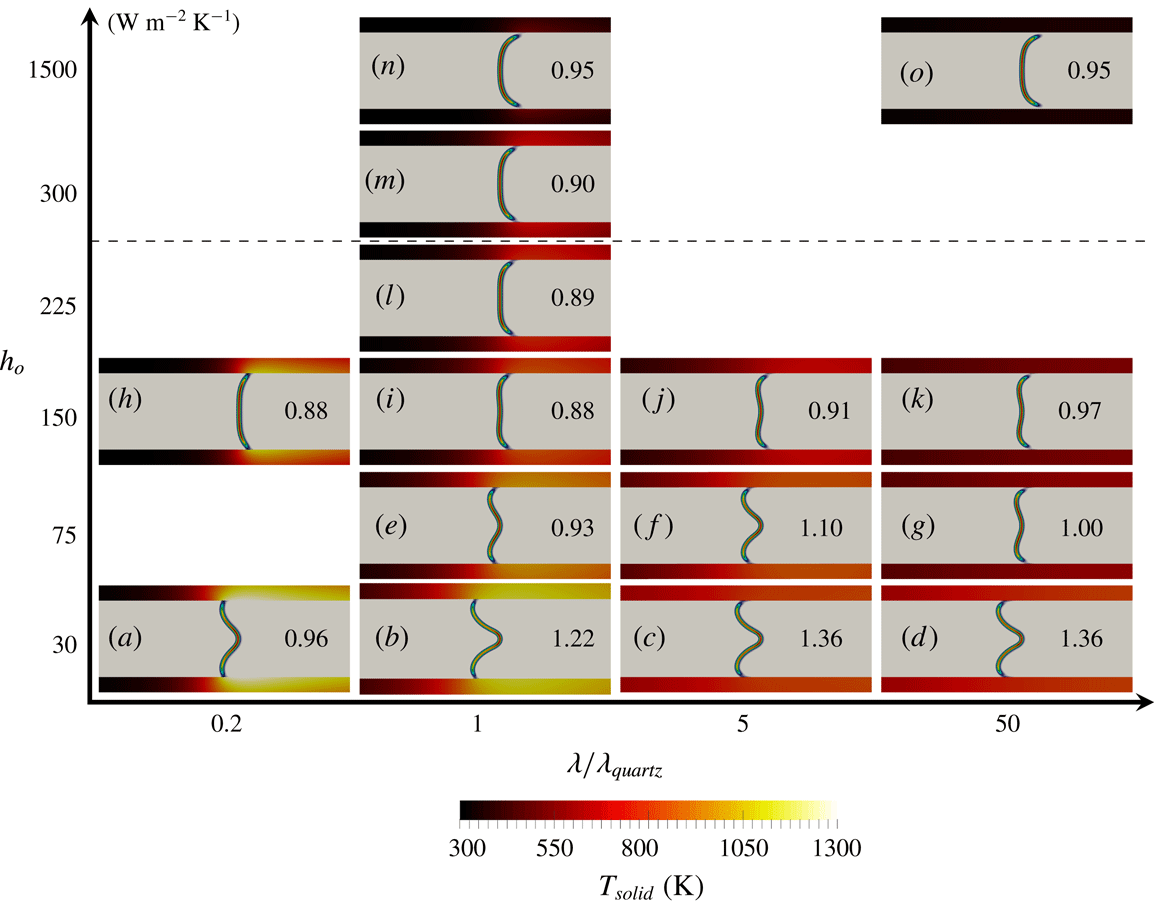
, which have been added to approach the asymptotic limit of very intense heat convection on the outside surface of the channel (figure 17). Even though unrealistic in practice, these additional cases are useful to better understand the limit regimes of the problem.
Flame response to heat-transfer properties.
 $h_{o}$
: heat transfer coefficient with surrounding air.
 $\unicode[STIX]{x1D706}$
: thermal conductivity of channel wall.
 $S_{L}/S_{L}^{o}$
indicated in the graphs. Conditions above dashed line are unrealistic in practice.

In a plane defined by (
 $\unicode[STIX]{x1D706}$
,
 $h_{o}$
), four asymptotic behaviours can be anticipated, which are recovered in the simulations:
(i) In the case of
 $\unicode[STIX]{x1D706}\rightarrow 0$
, the flux of heat in the wall vanishes and an adiabatic flame develops whatever the value of
 $h_{o}$
. Therefore for small value of
 $\unicode[STIX]{x1D706}$
, almost flat flames are expected. This is what is observed in figure 17(a,h) when decreasing
 $\unicode[STIX]{x1D706}$
by a factor 5 (
 $\unicode[STIX]{x1D706}/\unicode[STIX]{x1D706}_{quartz}=0.2$
). For
 $h_{o}$
set at
 $150~\text{W}~\text{m}^{-2}~\text{K}^{-1}$
, a small deviation from the adiabatic case is observed with a convex flame. For a smaller
 $h_{o}$
level, a larger temperature gradient develops in the solid, and a slightly concave shape flame appears (figure 17
a).
(ii) For very weak levels of the convective flux,
 $h_{o}\rightarrow 0$
, the outside surface of the wall is insulated and all of the heat transferred to the wall propagates in the solid in the longitudinal direction, downstream and upstream of the flame. The fresh gases collect heat, increasing their temperature and leading to an increase of the flame speed compare to the adiabatic case. This acceleration proceeds up to the point where a new balance is found between the upstream conduction of the heat extracted from the burnt gases, the preheating of the fresh gases and the amount of heat released by the flame. The flame shape should therefore be very similar to the one reported above for a quartz wall with heat transfer, with a flame speed measured above the adiabatic value
 $S_{L}^{o}$
. Starting from
 $\unicode[STIX]{x1D706}_{quartz}$
(figure 17
b), two of such cases are shown in figures 17(c) and 17(d) for
 $h_{o}=30~\text{W}~\text{m}^{-2}~\text{K}^{-1}$
with
 $\unicode[STIX]{x1D706}$
increased by the factors of 5 and 50. The flame shape is unchanged and the flame speed indeed increases with the rate of heat transfer in the wall. However, a smaller value of
 $\unicode[STIX]{x1D706}$
limits the diffusion of heat in the wall and the flame speed decreases, even below
 $S_{L}^{o}$
for
 $\unicode[STIX]{x1D706}/\unicode[STIX]{x1D706}_{quartz}=0.2$
(figure 17
a).
(iii) A wall with a very large level of conductivity,
 $\unicode[STIX]{x1D706}\rightarrow \infty$
, will behave as isothermal, with an almost uniform temperature in the solid. A temperature whose level varies according to the convective heat-transfer coefficient. For small values of
 $h_{o}$
, the wall will be isothermal and hot. For larger values of
 $h_{o}$
, an isothermal cold wall type flame with a convex shape is expected. The flame speed should also decrease with the increase of the level of heat extracted over the outside surface of the wall. This is confirmed in figure 17(d,g,k,o), when
 $h_{o}$
varies from
 $30~\text{W}~\text{m}^{-2}~\text{K}^{-1}$
to
 $1500~\text{W}~\text{m}^{-2}~\text{K}^{-1}$
, for
 $\unicode[STIX]{x1D706}/\unicode[STIX]{x1D706}_{quartz}=50$
. The flame speed diminishes from
 $1.36S_{L}^{o}$
(case d) to
 $0.95S_{L}^{o}$
(case o), with the amplification of the outside convective heat transfer
 $h_{o}$
. The flame shape is convex, as in the cold wall case, for the largest value of
 $h_{o}$
. Decreasing
 $h_{o}$
, the edge flame close to the wall is submitted to a smaller heat flux and it progressively moves upstream, up to the apparition of the flame shape with an inflexion point (figure 17
d), typical of a flame propagating in a boundary layer with both convective and conductive heat transfer in the wall.
(iv) For very large values of
 $h_{o}$
, whatever the value of
 $\unicode[STIX]{x1D706}$
, the wall becomes isothermal and the flame is of convex shape, as seen in figure 17(n,o) for
 $h_{o}=1500~\text{W}~\text{m}^{-2}~\text{K}^{-1}$
,
 $\unicode[STIX]{x1D706}_{quartz}$
and
 $50\unicode[STIX]{x1D706}_{quartz}$
.
Overall, the burning velocity
 $S_{L}$
increases with
 $\unicode[STIX]{x1D706}$
, the conductivity in the wall and
 $S_{L}$
decreases with an increase of
 $h_{o}$
, the convective heat-transfer coefficient (figure 17). These general trends may not be verified for the extreme values of
 $h_{o}$
(see for instance figure 17
m,n). For these high levels of
 $h_{o}$
, the flame propagates in the vicinity of an almost cold wall, with a pronounced lengthening of the edge flame because of quenching. A lengthening of the flame surface that is followed by an increase of the burning velocity. Similarly, for
 $h_{o}=75~\text{W}~\text{m}^{-2}~\text{K}^{-1}$
, when moving from 5
 $\unicode[STIX]{x1D706}_{quartz}$
(figure 17
f) to
 $50\unicode[STIX]{x1D706}_{quartz}$
(figure 17
g), the burning velocity decreases even though heat conductivity in the wall has been enhanced. Here, the wall becomes close to isothermal and the disappearance of the inflexion point in the flame shape leads to an almost planar flame, with a reduced burning velocity. Nevertheless, still looking at this case (figure 17
g), but in comparison to others at the same value of
 $\unicode[STIX]{x1D706}$
, the expected decay of the burning velocity when
 $h_{o}$
increases is found.
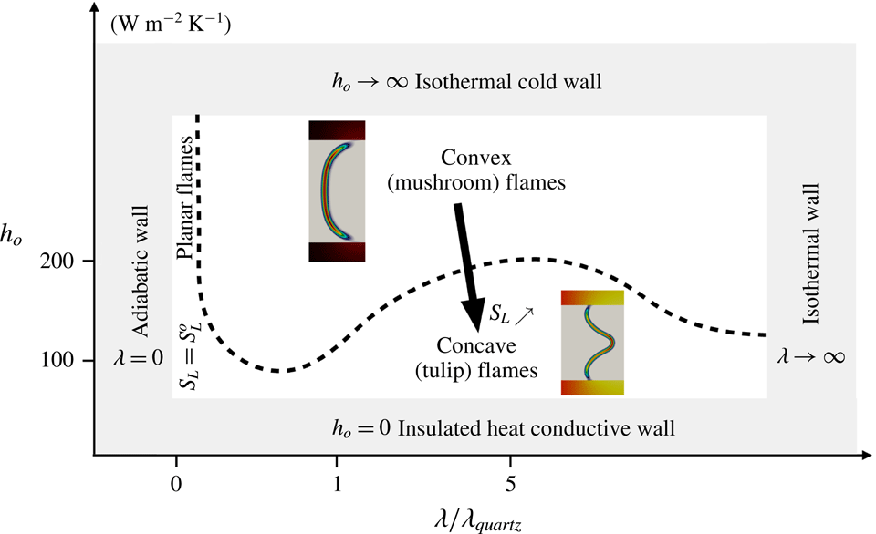
Diagram summarising the flame shape behaviour versus wall heat transfer parameters.
 $\unicode[STIX]{x1D706}$
: wall conductivity.
 $h_{o}$
: coefficient of convective heat transfer with outside environment. Internal channel height: 5 mm. Wall thickness: 1 mm. Stoichiometric
 $\text{CH}_{4}$
/air flame.

A diagram of axis (
 $\unicode[STIX]{x1D706},h_{o}$
) may be drawn to delineate between the flame regimes observed in the simulations and to provide the global picture summarising this work (figure 18). In the limit of an adiabatic wall, the flames are planar and feature the properties of a one-dimensional reactive front. For small levels of convective heat transfer over the external surface of the channel, the increase of the heat conductivity in the solid wall accelerates the edge flame at the wall leaving the centreline reaction zone behind. The flame front then becomes concave toward fresh gases on the axis of symmetry and propagates faster than the stoichiometric laminar burning velocity. Progressively increasing the heat loss at the wall through convection with ambient air, the propagation speed of the reactive front decreases close to the wall and at some point, the flame propagates faster along the centreline than close to the wall and the flame shape becomes convex, with a flame speed smaller than the stoichiometric burning velocity. It is important to note that figure 18 was drawn for the operating conditions studied (channel height and wall thickness). The exact location in this diagram where the transition in the flame shape occurs, is not as generic as the diagram asymptotic limits (boundaries of the diagram).
These results consolidate previously published findings on flame propagation in narrow channels, based on both experimental and numerical works, and the knowledge of these regimes may be of precious help in the design of small-scale combustion devices.
Acknowledgements
This work was granted access to the HPC resources of CCRT under the allocation A0032B07358 made by GENCI (Grand Equipement National de Calcul Intensif) and of CRIAAN (Centre Régional Informatique et d’Applications Numériques de Normandie). K.B. is funded by the Agence Nationale de la Recherche (ANR) under the project ANR-14-CE05-0030-MAPEE: ‘Microcombustion Assistée par Plasma et Excès d’Enthalpie’. The authors benefitted from fruitful discussions with Dr P. Domingo in the use of the SiTCom complex chemistry flow solver.
Appendix A. Verification of the reduced chemistry
Comparison between detailed (GRI-1.2 (Frenklach et al.
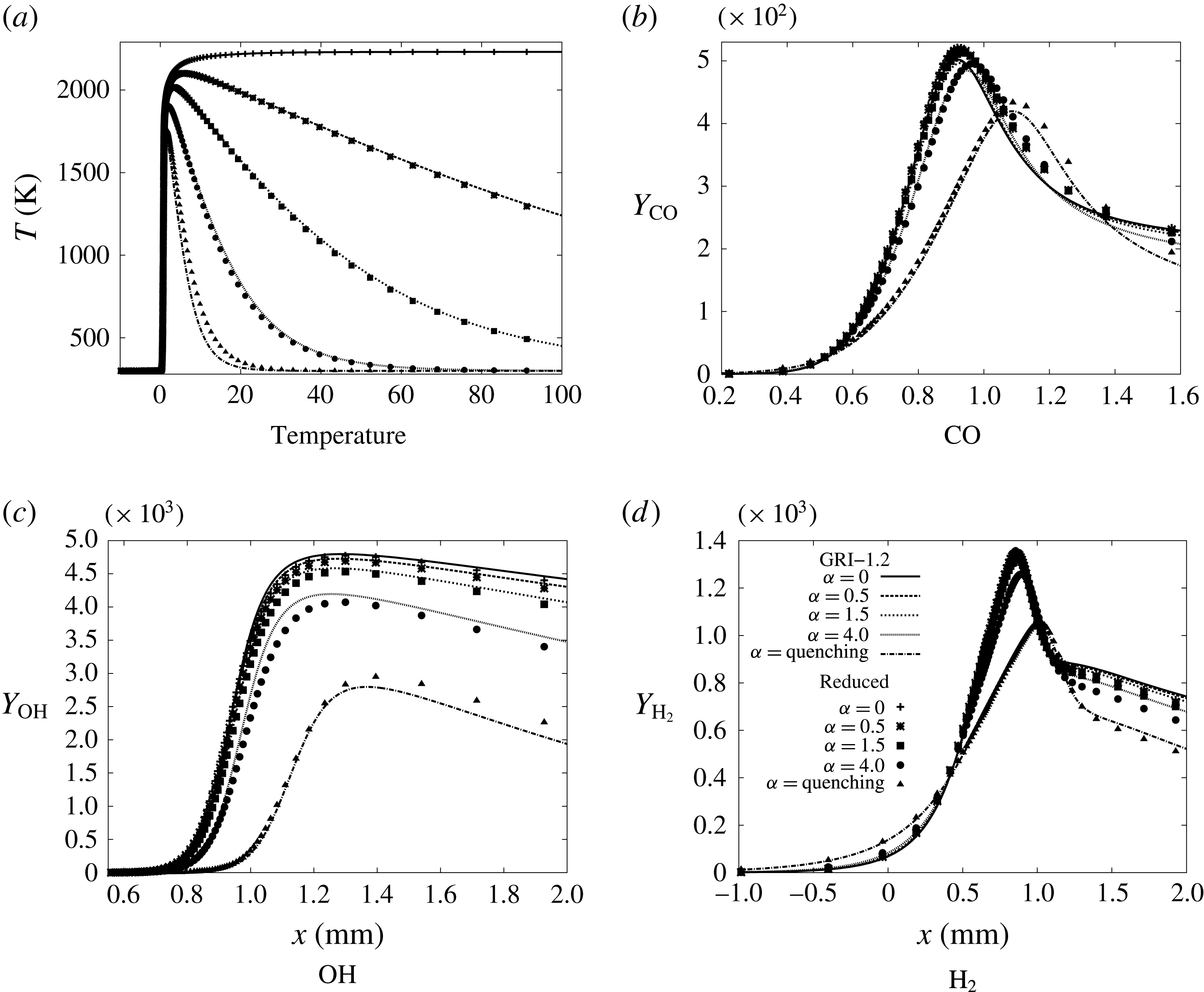
Reference Frenklach, Wang, Yu, Goldenberg, Bowman, Hanson, Davidson, Chang, Smith, Golden, Gardiner and Lissianski1995)) and reduced chemistry (table 2). Streamwise profiles at various
 $y$
distances from the axis (wall is at
 $y=-2.5~\text{mm}$
, see figure (c) for legend). Heat conductive wall case.

A first simulation with the quartz heat conductive wall is performed using the GRI-1.2 (Frenklach et al.
Reference Frenklach, Wang, Yu, Goldenberg, Bowman, Hanson, Davidson, Chang, Smith, Golden, Gardiner and Lissianski1995) methane–air detailed chemistry (figure 1). The resolution needed to capture the thin radical layers is
 $\unicode[STIX]{x1D6FF}_{x}=12.5~\unicode[STIX]{x03BC}\text{m}$
and this detailed mechanism involves 32 species and 177 reactions. To reduce the needed computing time and allow for addressing multiple cases, a similar simulation is performed with the reduced chemical scheme involving 15 species and 26 reactions given in table 2. This reduced methane–air chemistry was developed from the GRI-1.2 for the stoichiometric condition by applying an automated reduction and chemical rate optimisation procedure developed by Jaouen et al. (Reference Jaouen, Vervisch, Domingo and Ribert2017b
). The removing of some intermediate radical species allows for an increase of the mesh size up to
 $\unicode[STIX]{x1D6FF}_{x}=25~\unicode[STIX]{x03BC}\text{m}$
, followed by a decrease of the CPU time of the order of 10. If the distributions of major species are left unchanged by the chemical reduction, see for instance CO in figure 19(a,c), an unavoidable difference in the flame shape is observed (figure 20). The reduced chemical scheme was optimised to propagate the adiabatic flame at the speed of the detailed scheme. In the channel with heat transfer, the burning velocity which was equal to
 $53.65~\text{cm}~\text{s}^{-1}$
with the GRI-1.2, it is reduced down to
 $46.55~\text{cm}~\text{s}^{-1}$
with the simplified chemistry. This reduction by 13 % of the burning velocity is attributed to the evoked change in flame shape induced by small modifications to the intermediates species, as can be seen in the streamwise profiles along the channel for CH
 $_{3}$
, O and H
 $_{2}$
(figure 19). Approaching the wall, the decay of CH
 $_{3}$
is slightly more pronounced with the more detailed kinetics, because of the decomposition of CH
 $_{3}$
into intermediate radicals (line with triangles in figure 19
c,d), species which are missing in the reduced scheme. Differences also appear in the peak values reached in the streamwise direction for the various spanwise positions (figure 19
c,d). Other species, such as the radical O, have almost the same response with the two schemes, except when approaching the centreline (figure 19
e,f). The response of the di-hydrogen is, however, only weakly changed from the detailed to the reduced scheme (figure 19
g,h).
Comparison of flame shapes between detailed and reduced chemistry. Quartz heat conductive wall.

To further investigate the origin of the differences close to the wall between the detailed and the reduced forms of the chemistry, a steady one-dimensional freely propagating premixed flame submitted to various levels of heat loss in its burnt gases is simulated. The budget equations for the multicomponent flow are solved in their one-dimensional form, with an equation for the enthalpy cast as
 $$\begin{eqnarray}\frac{\unicode[STIX]{x2202}\unicode[STIX]{x1D70C}h}{\unicode[STIX]{x2202}t}+\frac{\unicode[STIX]{x2202}\unicode[STIX]{x1D70C}uh}{\unicode[STIX]{x2202}x}=\frac{\unicode[STIX]{x2202}}{\unicode[STIX]{x2202}x}\left(\unicode[STIX]{x1D706}\frac{\unicode[STIX]{x2202}T}{\unicode[STIX]{x2202}x}\right)-\frac{\unicode[STIX]{x2202}}{\unicode[STIX]{x2202}x}\left(\unicode[STIX]{x1D70C}\mathop{\sum }_{k=1}^{N}h_{k}Y_{k}V^{k}\right)-10^{5}\unicode[STIX]{x1D6FC}(T-T_{o}),\end{eqnarray}$$
where
 $\unicode[STIX]{x1D70C}$
is the density of the gas,
 $h$
is the enthalpy,
 $u$
is the flow velocity,
 $\unicode[STIX]{x1D706}$
is the thermal conductivity of the mixture,
 $T$
is the temperature,
 $V^{k}$
is the diffusion velocity of the
 $k$
th species, which is approximated as in the two-dimensional simulations from the mixture averaged model (Curtiss & Hirschfelder Reference Curtiss and Hirschfelder1949).
 $N$
is the number of species. The cold temperature is set to
 $T_{o}=300~\text{K}$
and the heat loss parameter
 $\unicode[STIX]{x1D6FC}$
in (A 1) is varied between 0 and 4, to be then increased again up to full quenching of the reaction zone. In the adiabatic case (
 $\unicode[STIX]{x1D6FC}=0$
), the GRI-1.2 mechanism returns a burning velocity of
 $38.91~\text{cm}~\text{s}^{-1}$
, a burnt gas temperature of 2231 K and a thermal flame thickness based on the temperature gradient of 0.427 mm. The adiabatic flame speed with the reduced scheme is
 $38.03~\text{cm}~\text{s}^{-1}$
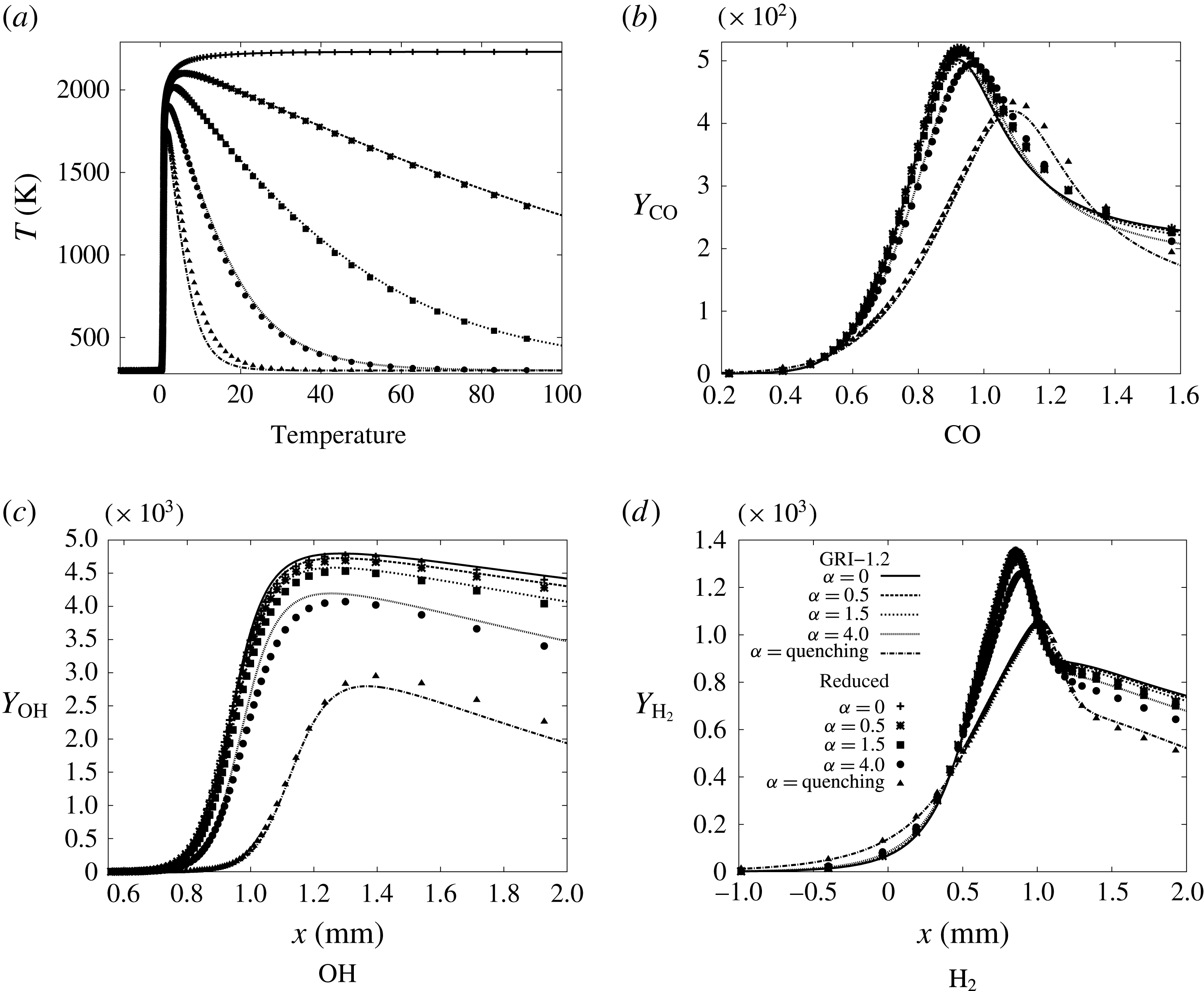
, the burnt gas temperature is 2231 K and the thermal flame thickness 0.451 mm. Therefore, the major adiabatic flame properties are similar with these two chemistries (2 % difference in the flame speed and 5 % in flame thickness), as are also the species distributions across the flame (figure 21). Concerning resolution requirements, figure 21(d) shows comparisons between chemical source distributions obtained with the laminar flame dedicated solver Cantera (Goodwin Reference Goodwin2009), including automatic mesh refinement, and the SiTCom-B simulation. The very good agreement confirms that the flame chemical structure is captured with a resolution of
 $25~\unicode[STIX]{x03BC}\text{m}$
.
In the cases with heat loss in the burnt gases, the profiles of major and intermediate species stay also very close, with nevertheless a visible departure which grows with the amount of heat removed from the flame (figure 22). For
 $\unicode[STIX]{x1D6FC}$
taking the values 0.5, 1.5 and 4 in (A 1), the maximum temperature levels in the flame are respectively 2011 K, 1903 K and 1827 K with the more detailed scheme and 2017 K, 1903 K and 1799 K with the reduced scheme. The full quenching of the flame is found at
 $\unicode[STIX]{x1D6FC}_{q}=8.60$
for the GRI-1.2 and
 $\unicode[STIX]{x1D6FC}_{q}=6.88$
for the reduced scheme, with a difference of 2.2 % in the temperature level when
 $\unicode[STIX]{x1D6FC}$
approaches its quenching value. These differences observed in the presence of heat losses, added to the 2 % difference in the one-dimensional flame speed and to the small modification of the flame shape, explains the 13 % difference in flame burning velocity in the channel. Despite those departures, which stay limited in amplitude, both detailed and reduced chemistry flames exhibit similar properties, at least when focussing on the flow dynamics and overall propagation and shape properties of the flame in the narrow channel.
Adiabatic one-dimensional freely propagating and stoichiometric premixed flame. (a–c) Comparison between GRI-1.2 (lines) and reduced chemistry (symbols). (d) Reduced chemistry. Comparison of Cantera (lines) and SiTCom-B (symbols).

Appendix B. Finding the burning velocity
 $S_{L}$

The value of
 $\boldsymbol{u}_{i}^{abs}$
is the absolute displacement velocity within the flame front of an isosurface defined from the mass fraction
 $Y_{i}$
. This absolute velocity measured in a fixed laboratory frame is decomposed into the fluid velocity
 $\boldsymbol{u}$
and
 $v_{i}\boldsymbol{n}$
, the relative progression velocity of the surface in its normal direction
 $\boldsymbol{n}=-\unicode[STIX]{x1D735}Y_{i}/|\unicode[STIX]{x1D735}Y_{i}|$
. Introducing the molecular diffusion velocity
 $\boldsymbol{V}^{i}$
of the
 $i$
th species, the budget equation for
 $Y_{i}$
may be written using these quantities:
 $$\begin{eqnarray}\unicode[STIX]{x1D70C}\frac{\unicode[STIX]{x2202}Y_{i}}{\unicode[STIX]{x2202}t}=-\unicode[STIX]{x1D70C}\boldsymbol{u}\boldsymbol{\cdot }\unicode[STIX]{x1D735}Y_{i}-\unicode[STIX]{x1D735}\boldsymbol{\cdot }(\unicode[STIX]{x1D70C}\boldsymbol{V}^{i}Y_{i})+\dot{\unicode[STIX]{x1D714}}_{i}=-\unicode[STIX]{x1D70C}\boldsymbol{u}_{i}^{abs}\boldsymbol{\cdot }\unicode[STIX]{x1D735}Y_{i}=-\unicode[STIX]{x1D70C}(\boldsymbol{u}+v_{i}\boldsymbol{n})\boldsymbol{\cdot }\unicode[STIX]{x1D735}Y_{i},\end{eqnarray}$$
leading to
 $$\begin{eqnarray}v_{i}=\frac{-\unicode[STIX]{x1D735}\boldsymbol{\cdot }(\unicode[STIX]{x1D70C}\boldsymbol{V}^{i}Y_{i})+\dot{\unicode[STIX]{x1D714}}_{i}}{\unicode[STIX]{x1D70C}|\unicode[STIX]{x1D735}Y_{i}|}.\end{eqnarray}$$
For
 $\boldsymbol{u}_{i}^{abs}=0$
, through the flame the flow velocity verifies
 $\boldsymbol{u}=-v_{i}\boldsymbol{n}$
. Then, the bulk velocity of the incoming flow exactly matches the burning velocity and the flame position is fixed in the reference frame of the laboratory. To reach this condition in the simulations of the narrow channel, the pseudo Galilean transformation discussed by Ruetsch, Vervisch & Liñán (Reference Ruetsch, Vervisch and Liñán1995) to stabilise freely propagating triple flames is applied. The component in the streamwise direction of the absolute velocity of the
 $\text{CH}_{4}$
isosurface is computed at
 $(x^{\star },y^{\star })$
, the location of the peak burning rate of
 $\text{CH}_{4}$
,
 $$\begin{eqnarray}u_{\text{CH}_{4}}^{abs}(x^{\star },y^{\star })=(\boldsymbol{u}(x^{\star },y^{\star })+v_{\text{CH}_{4}}(x^{\star },y^{\star })\boldsymbol{n}(x^{\star },y^{\star }))\boldsymbol{\cdot }\boldsymbol{e}_{x},\end{eqnarray}$$
where
 $\boldsymbol{e}_{x}$
is the streamwise unit vector and
 $v_{\text{CH}_{4}}$
is calculated with the relation (B 2). If
 $u_{\text{CH}_{4}}^{abs}(x^{\star },y^{\star })\neq 0$
the flame moves in the domain, because the relative progression velocity
 $v_{\text{CH}_{4}}(x^{\star },y^{\star })\boldsymbol{n}(x^{\star },y^{\star })\boldsymbol{\cdot }\boldsymbol{e}_{x}$
is not balanced by the inflow velocity
 $\boldsymbol{u}(x^{\star },y^{\star })\boldsymbol{\cdot }\boldsymbol{e}_{x}$
. The streamwise flow momentum may be rescaled in
 $\unicode[STIX]{x1D70C}(x,y)u^{new}(x,y)$
over the computational domain, including boundary conditions, to secure a zero absolute velocity of the reactive front,
 $$\begin{eqnarray}\unicode[STIX]{x1D70C}(x,y)u^{new}(x,y)=\unicode[STIX]{x1D70C}(x,y)u(x,y)-(\unicode[STIX]{x1D70C}(x^{\star },y^{\star })u_{\text{CH}_{4}}^{abs}(x^{\star },y^{\star }))F(y).\end{eqnarray}$$
In this relation,
 $F(y)=(1-(2y/\ell _{i})^{2})$
accounts for the presence of the wall in the no-slip cases, in the slip-wall case
 $F(y)=1\,\forall y$
. The kinetic energy part of the transported total sensible energy is rescaled accordingly. This transformation is applied only every 500 iterations until
 $u_{\text{CH}_{4}}^{abs}(x^{\star },y^{\star })<10^{-6}S_{L}^{o}$
. From this point, the simulation is pursued over 15 characteristic stoichiometric flame times (
 $\unicode[STIX]{x1D6FF}_{th}/S_{L}$
), to fully secure convergence with residuals below
 $10^{-6}$
. As a check, this procedure was also applied to one-dimensional flames with an observed speed up to the convergence, to reach solutions perfectly matching those obtained using the dedicated flame solver Cantera (Goodwin Reference Goodwin2009).