I. INTRODUCTION
The study of atomic rearrangements and disordering due to the interaction of energetic ions with solids in extremely short time-scales is a critical issue for advancing the fundamental understanding of the radiation damage mechanisms in ceramics. One event of interest occurs when the kinetic energy from incident ions is transferred to the electrons of the target material through inelastic interactions, and most of that electronic energy is transferred back to the atomic lattice as a thermal spike via electron-phonon coupling. Reference Studer and Toulemonde1,Reference Toulemonde, Assman, Dufour, Meftah, Studer and Trautmann2 It leads to the creation of cylindrical damaged regions, generally referred as ion tracks. The study of ion track formation is critical for various areas of research, e.g., radiation damage in nuclear fuels, Reference Matzke and Kinoshita3 nuclear waste immobilization, Reference Lang, Zhang, Zhang, Wang, Lian, Weber, Schuster, Trautmann, Neumann and Ewing4 geological age-dating, Reference Price5 cosmic rays induced damage in electronic devices in space, Reference Boscherini, Adriani, Bongi, Bonechi, Castellini, D'Alessandro, Gabbanini, Grandi, Menn, Papini, Ricciarini, Simon, Spillantini, Straulino, Taccetti, Tesi and Vannuccini6 ion-irradiation induced complex nanostructures for electronics, energy storage, and conversion. Reference Weber, Zarkadoula, Pakarinen, Sachan, Chisholm, Liu, Xue, Jin and Zhang7–Reference Aidhy, Sachan, Zarkadoula, Pakarinen, Chisholm, Zhang and Weber9
Advanced characterization of ion tracks in pyrochlore structured (Gd2Ti2O7 and Gd2TiZrO7) complex oxides is the focus of the present work. The pyrochlore structure consists of an ordered arrangement of A and B cation sites occupied by Gd and Ti (or Zr), respectively, and O atom at anion sites. As the pyrochlore structure is a derivative of ideal fluorite structure with 1/8th fewer anions, it contains O atoms occupying 48f and 8b sites and a vacancy at 8a site. Reference Sickafus, Minervini, Grimes, Valdez, Ishimaru, Li, McClellan and Hartmann10 Due to their structure and properties, these materials are foreseen as potential materials for nuclear waste immobilization, Reference Ewing11 inert matrix fuels for burning nuclear waste, Reference Wang, Begg, Wang, Ewing, Weber and Kutty12 as well as fast-ion conductors in solid oxide fuel cell application. Reference Aidhy, Sachan, Zarkadoula, Pakarinen, Chisholm, Zhang and Weber9,Reference Tuller, Kasap and Capper13
There are various aspects of track morphology, such as concentric track structures, metastable phase formation, and strain that need to be understood thoroughly to advance predictive behavior and potential applications for these materials. X-ray diffraction, Rutherford backscattering, Raman spectroscopy, photoluminescence, transmission electron microscopy (TEM), and scanning TEM (STEM) have been the primary characterization techniques used in ion track studies. Reference Sattonnay, Sellami, Thomé, Legros, Grygiel, Monnet, Jagielski, Jozwik-Biala and Simon14–Reference Jozwik-Biala, Jagielski, Arey, Kovarik, Sattonnay, Debelle, Mylonas, Monnet and Thomé16 In spite of being widely used to characterize ion-irradiated materials, all the techniques, except TEM/STEM, do not provide information with sub-nanometer resolution. In addition, TEM imaging, which is based on the phase, thickness, and strain contrast, provides complicated and more ambiguous information. Among all these techniques, imaging in STEM with an aberration corrected probe has come out as a superior technique for providing the atomic scale details of track morphology. Reference Pennycook, Chisholm, Lupini, Varela, Borisevich, Oxley, Luo, van Benthem, Oh, Sales, Molina, Garcia-Barriocanal, Leon, Santamaria, Rashkeev and Pantelides17 An aberration corrected STEM provides the unique capability to obtain sub-angstrom resolution information of atomic structures with high-angle annular dark field (HAADF), medium-angle annular dark field (MAADF), and annular bright field (ABF) imaging and complimentary electron energy-loss spectroscopy techniques. There have been few applications of STEM to-date in studying ion-irradiated materials. So far, researchers have used HAADF imaging in a STEM to understand the interface strain, Reference Aidhy, Sachan, Zarkadoula, Pakarinen, Chisholm, Zhang and Weber9 phase transformation, Reference Jozwik-Biala, Jagielski, Thome, Arey, Kovarik, Sattonnay, Debelle and Monnet15 and track morphology Reference Jozwik-Biala, Jagielski, Arey, Kovarik, Sattonnay, Debelle, Mylonas, Monnet and Thomé16 of ion tracks in Gd2Ti2O7. It provides significantly larger potential for advancing our understanding of track formation, morphology, and unique properties.
In the present work, we use various imaging techniques in an aberration corrected STEM to address critical issues related to quantifying ion track morphology in pyrochlore structured Gd2Ti2O7 and Gd2TiZrO7. The track morphology is studied as a function of incident ion energy-loss along the whole length of an ion track, i.e., ∼7.5 µm. We also show how various imaging techniques can be utilized to extract different information. The phase identification in an ion track is performed by using HAADF imaging. Finally, we show a method to reconstruct a 3-dimensional view of an ion track to understand the track morphology along increment track lengths at the nm-scale. With these results, we exhibit the strength of aberration corrected STEM in understanding the behavior of materials under ion-irradiation.
II. EXPERIMENTAL PROCEDURE
A. Ion-irradiation
The Gd2Ti2O7 and Gd2TiZrO7 samples were prepared by the sol–gel method, followed by a sintering process at 1875 K for 50 h in air. Two sets of Gd2Ti2O7 samples were prepared for this study, (a) ∼40 µm thick and (b) ∼1 mm thick, which were irradiated by 2.2 GeV Au and 55 MeV I ions, respectively. The Gd2TiZrO7 samples with ∼40 µm thickness were irradiated by 2.3 GeV Pb ions. For creating isolated ion tracks, the fluence was kept at 5 × 10¹⁰ ions per cm2 in all the experiments. The UNILAC linear accelerator facility in the GSI Helmoltz Center for Heavy Ion Research in Darmstadt, Germany was used for the 2.2 GeV Au and 2.3 GeV Pb-irradiation experiments. The details of irradiation conditions are described in Table I. For clarity, various Gd2Ti2O7 (55 MeV I and 2.2 GeV Au) and Gd2TiZrO7 (2.3 GeV Pb) samples are labeled as A, B, and C, respectively.
Details of materials and condition used for ion-irradiation experiments and SRIM calculations.

B. Stopping and range of ions in matter (SRIM) calculations
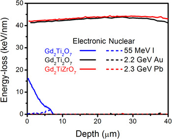
In the present study, the SRIM code was used to estimate electronic (S e) and nuclear (S n) energy-losses during the ion-irradiation process in these pyrochlore materials. Reference Ziegler, Biersack and Ziegler18 The details regarding materials properties and irradiation conditions are given in Table I. The simulations were run for 1000 ions. Figure 1 shows the electronic and nuclear energy-loss of energetic ions in various Gd2Ti2O7 and Gd2TiZrO7 materials as a function of penetration depth. The electronic energy-loss in both Gd2Ti2O7 and Gd2TiZrO7 samples irradiation by GeV energy ions is almost constant throughout the sample thickness (i.e., ∼40 µm), while nuclear energy-loss is negligible. The projected range of 55 MeV I ions in Gd2Ti2O7 sample is ∼7.5 µm.
Electronic and nuclear energy-loss of energetic ions in various Gd2Ti2O7 and Gd2TiZrO7 as a function of penetration depth. Electronic and nuclear energy-loss of various ions in materials are plotted by solid and dotted lines, respectively. Nuclear energy-loss for 2.2 GeV Au irradiated Gd2Ti2O7 and 2.3 GeV Pb irradiated Gd2TiZrO7 are almost negligible for the thickness of sample (i.e., ∼40 µm) and overlay with x-axis.

C. STEM characterization
HAADF imaging was performed on various samples in a 5th order aberration corrected scanning transmission electron microscope (UltraSTEM200, Nion, Seattle, Washington) operating at 200 kV. The HAADF images were acquired with an inner collector semi-angle of 65 mrad, while ABF images were collected with a semi-angle of 15–28 mrad. The probe forming aperture half angle of 30 mrad was used in the experiments. The electron probe current used in the different experiments was kept 28 ± 2 pA. The EELS data were acquired with the collection angle of 48 mrad. The samples for STEM analysis were prepared by conventional mechanical thinning, precision polishing, and ion-milling in a liquid N2 environment. The plan-view samples of Gd2Ti2O7 and Gd2TiZrO7 (both ∼40 µm thick) irradiated by GeV energy ions were prepared at the ∼10 µm depth from the irradiated surface. The plan-view sample of Gd2Ti2O7 irradiated by 55 MeV I ions was prepared at ∼3 µm from surface, following the procedure described in detail elsewhere. Reference Sachan, Pakarinen, Liu, Patel, Chisholm, Zhang, Wang and Weber8
III. RESULTS AND DISCUSSION
A. Ion track morphology
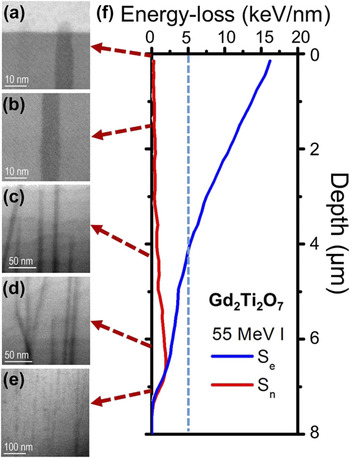
To study the track morphology as a function of incident ion energy-loss in the material, a series of cross-sectional ABF images were acquired in sample A (Gd2Ti2O7 irradiated by 55 MeV I), as shown in Fig. 2. The threshold electronic energy-loss (S th) for track formation in Gd2Ti2O7 is reported to be ∼5 keV/nm, which is shown by a dotted line in Fig. 2(f). Based on the ABF images obtained from different depths in the material, the following conclusions correlating the effect of energy-loss are reported:
-
(i) Figure 2(a) shows a straight ion trajectory on the surface of the Gd2Ti2O7. The track formation at the surface is a result of the electronic energy-loss, S e = 16 keV/nm, at the surface for an incident 55 MeV I ion, which is well above the electronic stopping threshold, S th, for track formation. The nuclear energy-loss, S n, at the surface is negligible and thus does not contribute in track formation. It is also seen that the ion track makes an amorphous cap on the surface due to the ejection of melted material to the free surface during the event of track formation. As a consequence, it is possible to have relatively lower materials density at the surface of Gd2Ti2O7.
-
(ii) A straight, continuous and uniform track is shown in Fig. 2(b), which represents the tracks formed at a depth between 1 and 2 µm. In this range, S e (10–12.5 keV/nm) is still significantly higher than the S th, while S n is negligible.
-
(iii) The presence of continuous ion tracks is shown in Fig. 2(c), which correspond to the tracks formed at the depth 3–4 µm. Tracks with parallel, as well as nonparallel trajectories, are observed in this depth region. The nonparallel tracks are formed, as electronic energy-loss of ions gradually decreases and approached close to threshold.
-
(iv) The nonparallel track formation [Fig. 2(d)] is more prominent at the depths where electronic energy-loss is equal to or less than the threshold energy-loss. In this stage, nuclear energy-loss is also prominent and plays a role in track formation by creating localized lattice disorder. Reference Weber, Zarkadoula, Pakarinen, Sachan, Chisholm, Liu, Xue, Jin and Zhang7,Reference Weber, Duffy, Thomé and Zhang19 The figure shows a clear evidence of an elastic (nuclear) scattering event with a lattice atom that results in a change in trajectory of the traversing ion.
-
(v) In Fig. 2(e), the image shows discontinuous ion tracks as well as accumulation of damaged regions, which takes place at the end of range for the ions. In this region, the discontinuous tracks are made due to the local stochastic increase in the ion energy-loss caused by possible nuclear energy-loss contribution. Reference Jozwik-Biala, Jagielski, Arey, Kovarik, Sattonnay, Debelle, Mylonas, Monnet and Thomé16 Such behavior is observed on the low energy side of the Bragg peak, where ion velocity effects are very prominent and point and planar defects are formed along with discontinuous disordered regions. Reference Toulemonde, Assman, Dufour, Meftah, Studer and Trautmann2
Ion track morphology at different depths in the material. The track characteristics vary as a function of inelastic energy-loss which decreases along the depth in the Gd2Ti2O7 irradiated by 55 MeV I (sample A).

B. Collection angle dependent ion track imaging
STEM has the capability of acquiring images with varying collection angles, which provide different information, such as Z-contrast, strain contrast, and diffraction contrast. Reference Marks and Voyles20
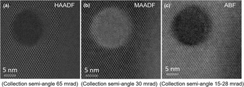
Figure 3 shows the HAADF, MAADF, and ABF image of an ion track from sample B. The HAADF and MAADF images in (a) and (b) were collected with an inner semi-collection angle of 65 and 30 mrad, while ABF image was collected with a semi-angle between 15 and 28 mrad. A contrast change in the amorphous ion track is observed between HAADF and MAADF images due to the addition of a strain contrast in the MAADF images along with atomic number (Z) dependent contrast. Figure 3(a) shows the HAADF image of an ion track without the influence of strain, while a dominating strain contrast is apparent around the amorphous ion track in MAADF image shown in Fig. 3(b). In addition, the overall contrast of image is also changed as an effect of strain in the material. ABF images are dominated by diffraction and strain contrast and are sensitive to anion positioning. The figure shows the additional dark contour around the amorphous track similar to that previously observed by other research groups. Reference Zhang, Lang, Ewing, Devanathan, Weber and Toulemonde21,Reference Lang, Toulemonde, Zhang, Zhang, Tracy, Lian, Wang, Weber, Severin, Bender, Trautmann and Ewing22
A plan-view image of an ion track in sample B acquired by ADF detector with inner semi-collection angle of (a) 65 mrad, (b) 30 mrad, and by ABF detector with (c) 15–28 mrad. (a) shows the defect-fluorite phase formation around the amorphous track identified by atomic column intensity analysis, while (b) demonstrates additional strain contrast around the ion track. (c) shows the ion track with strain and phase contrast.

C. Phase identification
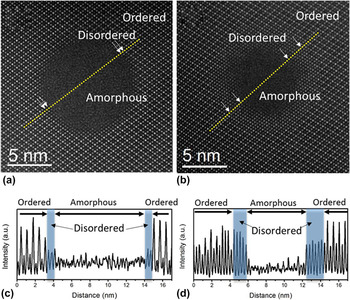
The atomic column intensity in HAADF/STEM imaging directly depends on the effective atomic number (∝Z 2). As bright field images are influenced by phase and thickness contrast and often have additional interfering Fresnel contrast at the interfaces, as shown in Fig. 3(c), the intensity analysis in HAADF images provides a solution to identify different phases or atomic arrangements more accurately. Figure 4 shows the HAADF images and the corresponding atomic column intensity analysis in sample B of Gd2Ti2O7 [Figs. 4(a) and 4(b)] and sample C of Gd2TiZrO7 [Figs. 4(c) and 4(d)], respectively. These samples are chosen for the comparison due to similar incident ion velocity (11.1 MeV per nucleon) as well as the electronic energy-loss (∼40 keV/nm) at the depth of ∼10 µm where STEM analysis is performed. The intensity analysis is performed along the dotted line shown in the HAADF images and shown in Figs. 4(b) and 4(d). Here, the analyzed ion tracks were verified to be parallel (not tilted) relative to the electron beam incidence by through focus imaging. The details are elaborated later in the part D of the present work. The presence of a disordered crystalline phase is observed between the ordered matrix and the amorphous phase in the ion track, which shows equal intensity in each atomic column [indicated by shadowed region in Figs. 4(b) and 4(d)]. The disordered phase is identified as a defect-fluorite phase consistent with previous reports. Reference Jozwik-Biala, Jagielski, Thome, Arey, Kovarik, Sattonnay, Debelle and Monnet15,Reference Lang, Toulemonde, Zhang, Zhang, Tracy, Lian, Wang, Weber, Severin, Bender, Trautmann and Ewing22,Reference Lang, Lian, Zhang, Zhang, Weber, Trautmann and Ewing23 The lateral width of the defect-fluorite phase is measured to be ∼0.5 nm in sample B and 1.8–2.1 nm (5–7 atomic planes) in sample C. These results show that the HAADF/STEM imaging method is critical for more accurate analysis of the disordered phase formation in ion tracks, which were previously reported to be 1–2 nm by HRTEM imaging based analysis. Reference Lang, Toulemonde, Zhang, Zhang, Tracy, Lian, Wang, Weber, Severin, Bender, Trautmann and Ewing22,Reference Lang, Devanathan, Toulemonde and Trautmann24
A HAADF image of an ion track in (a) sample B and (b) C. The intensity profile along the dotted line in HAADF images are shown in (c) and (d), respectively, for Gd2Ti2O7 and Gd2TiZrO7. The measured disordered crystalline (defect-fluorite) layer is indicated in the HAADF images (by arrows) as well as in intensity profile by shadowed region. The lateral width of defect-fluorite ring is increased by substituting Ti by Zr atoms.

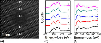
An energy-loss near edge structure analysis of Ti L2,3-edge (456 eV) and O K-edge (532 eV) analysis is shown in Fig. 5 corresponding to the ordered, disordered (defect fluorite), and amorphous phased regions that are identified earlier in Fig. 4, in sample C of Gd2TiZrO7. It is seen from the figure that crystal field splitting exists for all three forms of Gd2TiZrO7 that indicates short-range ordering of Ti–O bonding persisting even in the amorphous phase. This is consistent with the previous structural data that showed local order in the defect-fluorite phase. Reference Sachan, Liu, Aidhy, Zhang, Chisholm and Weber25,Reference Shamblin, Feygenson, Neuefeind, Tracy, Zhang, Finkeldei, Bosbach, Zhou, Ewing and Lang26 Second, an energy shift in the Ti L2,3-edge character is observed between the ordered pyrochlore and the disordered defect-fluorite structures, whereas its character remains largely unchanged between the disordered defect fluorite and the amorphous phase of Gd2TiZrO7. The only difference observed between the Ti EEL spectra of disordered defect-fluorite and amorphous phase is slightly more peak broadening in the amorphous structure as compared to defect-fluorite. It is suggested that this peak energy deviation takes place due to change in Ti–O local environment in disordered structures from the octahedral coordinated one in ordered pyrochlore structure. O K-edge spectra for the same regions in Gd2TiZrO7, presented in Fig. 5(c), exhibit a clear existence of a pre-peak in the ordered pyrochlore that merges with the main peak in the disordered defect fluorite as well as in the amorphous phase. This suggests an overlapping of energy bands due to structural disordering. Overall, it is observed that atomically disordered structures (defect fluorite and amorphous) show very similar electronic structure in spite of different atomic arrangements, while exhibiting a clear distinction from the ordered pyrochlore structure in Gd2TiZrO7. These observations are consistent with the findings in formed phases in Gd2Ti2O7.
Electron energy-loss spectra for (b) Ti L23-edge and (c) O K-edge corresponding to the 1–5 regions marked in (a) a HAADF image of an ion track in sample C. Region 1, 5, Region 2, 4, and Region 3 correspond to ordered, disordered, and amorphous phases, respectively.

D. Quantitative 3-dimensional reconstruction of an ion track
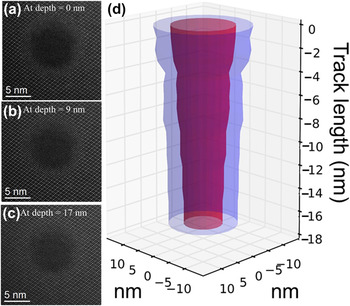
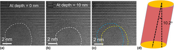
One of the challenges in the study of the ion tracks is to get more quantitative analysis of the atomic structure and the morphology. As shown earlier in Fig. 2, cross-sectional imaging is an useful tool to study the morphological changes in track formation due to change in the energy-loss of incident ions, but it lacks in providing atomic scale information of atomic arrangement during track formation. The image is the collective information of an amorphous ion track (∼5–10 nm) embedded in ∼50 nm crystalline matrix in a cross-section sample. It has been reported that HAADF imaging in a STEM is a powerful method to get atomic-level details of structure by through focus depth-sectioning. Reference Pennycook, Chisholm, Lupini, Varela, Borisevich, Oxley, Luo, van Benthem, Oh, Sales, Molina, Garcia-Barriocanal, Leon, Santamaria, Rashkeev and Pantelides17,Reference Klenov and Stemmer27–Reference Ishikawa, Lupini, Findlay, Taniguchi and Pennycook29 With the depth-sectioning in aberration corrected STEM, 3-dimensional reconstruction of nanoscale features such as catalytic metal clusters were studied previously. Reference Borisevich, Lupini and Pennycook28 The identification of 3-dimensional location of single dopant atom with atomic precision in a bulk crystal of AlN by imaging in a STEM demonstrates the strength of the technique. Reference Ishikawa, Lupini, Findlay, Taniguchi and Pennycook29 To better understand ion track morphology, our group recently showed the presence of dramatic diametric fluctuations in track morphology in sample C of Gd2TiZrO7 at constant energy-loss (∼40 keV/nm) with the help of sequential depth-dependent plan-view HAADF imaging. Reference Sachan, Zarkadoula, Lang, Trautmann, Zhang, Chisholm and Weber30 Figure 6 illustrates HAADF images of an ion track obtained by focusing at different depths [(a) surface, (b) 9 nm, and (c) 17 nm] within the specimen. It is evident from the images that the diameter of the track decreases from 7.4 nm (on surface) to 4.5 nm (over a track length of 17 nm). A three-dimensional reconstruction of the ion track is shown in Fig. 6(d) based on the acquired depth-dependent plan-view HAADF images of the same ion track. The amorphous core is presented by red, while defect-fluorite shell is represented by blue color. The figure clearly shows the gradual decrease of diameter along the incremental length of track. Although these short-range diametric fluctuations within a track length of 17 nm in Gd2TiZrO7 are unexpected due to constant electronic energy-loss, its evolution is attributed to partial substitution of Ti atoms by Zr atoms, which have a large difference in ionic radii, on the B-site in pyrochlore lattice. Because of this difference, local energy dissipation, electron-phonon coupling, and epitaxial crystallization processes are all affected. This random distribution of Ti and Zr atoms leads to a local competition between amorphous phase formation (favored by Ti atoms) and defect-fluorite phase formation (favored by Zr atoms) during the recrystallization process and finally introduces large radial variations in track morphology. Reference Sachan, Zarkadoula, Lang, Trautmann, Zhang, Chisholm and Weber30 The present study shows the capability of HAADF/STEM to extract more quantitative information by using depth-dependent image acquisition. This technique has also been utilized in 3-dimensional reconstruction of an ion track in Gd2Ti2O7 and in determining the tilting of the track with respect to viewing plane. Figure 7 shows the plan-view HAADF images of a track in sample B by focusing the electron probe on (a) surface and (b) at a depth of 10 nm. Figure 7(c) shows the projected change in the track position with depth. The reconstructed figure of an ion track is shown in Fig. 7(d), which shows a tilt of 10.2 ± 0.1° in the ion track. This method is also used to select the ion tracks with no tilt relative to electron beam incidence and embedded in low order zone axis for the quantitative measurements, as shown earlier in Fig. 4.
The plan-view HAADF images (a–c) of an ion track in sample C as a function of depth in the material illustrating the variation in the track diameter along the track length. Images were taken by changing focus (surface, 9 and 17 nm) of electron probe in the sample. (d) A 3-dimensional reconstruction of the ion track based on the series of depth-dependent plan-view HAADF images. The images were acquired with 1 nm focus step for 17 nm into the material.

The plan-view HAADF images of an ion track in sample B of Gd2Ti2O7 acquired by focusing on (a) surface and (b) at a depth of 10 nm. The track is formed by irradiating Gd2Ti2O7 by 2.2 GeV Au ion. (c) shows the projected changes in track position along the track length. (d) shows the reconstructed track based on the depth-dependent plan-view imaging of the ion track. The figure shows the ion track is tilted by 10.2° from the normal surface at which images were acquired.

IV. CONCLUSION
The present study provides new insights and methods of quantitative analysis for ion track morphology by using an aberration corrected STEM. It is shown that ABF imaging in STEM is used to understand the morphological changes of track as a function of ion energy-loss in the Gd2Ti2O7. A Z-contrast dependent image analysis method is also shown in the study to identify the ordered–disordered transitions at atomic scale. A depth-dependent HAADF image analysis of an ion track is shown to understand the hidden atomic scale variations in the structure along the track at nm-scale and is used for 3-dimensional reconstruction of an ion track.
ACKNOWLEDGMENTS
This research was supported by the U.S. Department of Energy, Office of Science, Basic Energy Sciences, Materials Science and Engineering Division. A portion of the experiments were conducted at the Center for Nanophase Materials Sciences, which is a DOE Office of Science User Facility.