Introduction
The development of clean and renewable energy is vital to meet ever-increasing global energy demands arising from rapid economic expansion and increasing world population, while minimizing fossil-fuel depletion, pollution, and global warming.Reference Doung1 Currently, new technologies for energy conversion (e.g., solar cells and fuel cells) and energy storage (e.g., supercapacitors and batteries) are under intensive research. Because the performance of these devices depends strongly on the materials employed, various emerging nanomaterials with desired nanostructures and large surface/interface areas have been developed for applications in energy-related devices.Reference Dai2 Of particular interest are carbon nanomaterials for energy applications.
Graphene, in particular, has received considerable attention because of its unique properties, including high thermal conductivity (∼5000 W m–1 K–1), high electrical conductivity (108 S m–1), high transparency (absorbance of 2.3%), great mechanical strength (breaking strength of 42 N m–1 and Young’s modulus of 1.0 TPa), inherent flexibility, high aspect ratio, and large specific surface area (2.63 × 10⁶ m2 kg–1).Reference Novoselov, Geim, Morozov, Jiang, Zhang, Dubonos, Grigorieva and Firsov3, Reference Geim and Novoselov4 Graphene sheets of different sizes and defect contents can be prepared by various approaches, including manual mechanical cleavage of graphite with adhesive tape,Reference Novoselov, Geim, Morozov, Jiang, Zhang, Dubonos, Grigorieva and Firsov3 epitaxial growth on single-crystal SiC,Reference Emtsev, Bostwick, Horn, Jobst, Kellogg, Ley, McChesney, Ohta, Reshanov, Röhrl, Rotenberg, Schmid, Waldmann, Weber and Seyller5 chemical vapor deposition (CVD) on metal surfaces,Reference Reina, Jia, Ho, Nezich, Son, Bulovic, Dresselhaus and Kong6 oxidation–exfoliation–reduction of graphite powder,Reference Eda and Chhowalla7 exfoliation of graphite through sonication/intercalation,Reference Lotya, Hernandez, King, Smith, Nicolosi, Karlsson, Blighe, De, Wang, McGovern, Duesberg and Coleman8 and organic coupling reactions.Reference Wang, Zhi, Tsao, Tomović, Li and Müllen9 Among these approaches, oxidation–exfoliation of graphite, followed by solution reduction, can be used to achieve large-scale production of graphene.Reference Lotya, Hernandez, King, Smith, Nicolosi, Karlsson, Blighe, De, Wang, McGovern, Duesberg and Coleman8 Graphene can also be readily doped with heteroatomsReference Qu, Liu, Baek and Dai10 (e.g., nitrogen, boron) or modified with organic molecules, polymers, or inorganic components.Reference Stankovich, Dikin, Dommett, Kohlhaas, Zimney, Stach, Piner, Nguyen and Ruoff11 The resultant soluble graphene derivatives can be processed into functional films by solution processing for many functional devices, such as sensors, actuators, field-effect transistors, solar cells, supercapacitors, and batteries.Reference Sun, Wu and Shi12–Reference Liu, Li, Ma and Cheng17 In this article, we summarize progress in the development of graphene-based materials for energy-conversion and -storage applications and discuss some challenges in this exciting field.
Graphene for energy conversion
It is estimated that the world will need to double its energy supply by 2050,Reference Doung1 so it is of paramount importance to develop new types of energy sources. Compared to conventional energy materials, carbon nanomaterials exhibit unusual size- and surface-dependent (e.g., morphological, electrical, optical, and mechanical) properties that enhance energy-conversion performance. Specifically, considerable efforts have been expended to exploit the unique properties of graphene in high-performance energy-conversion devices, including solar cells and fuel cells.
Solar cells
Inorganic semiconductors, such as amorphous silicon, gallium arsenide, and sulfide salts, have been widely used in conventional photovoltaic cells, in which free electrons and holes are produced directly upon photon absorption.Reference Bube19 Although a power conversion efficiency (PCE) of more than 40% has now been achieved for inorganic (III–V semiconductor) multijunction solar cells in the laboratory,Reference Green, Emery, King, Igari and Warta20 the widespread use of inorganic solar cells is still limited because of difficulties in modifying the bandgap of inorganic semiconductors and high costs associated with the elaborate fabrication processes involving elevated temperature and high vacuum.Reference Swanson21 These inorganic solar cells are still too expensive to compete with conventional grid electricity.Reference Johnson22 Alternative approaches using organic or polymer materials have received considerable attention because of their low cost, light weight, flexibility, and solution processability.Reference Krebs23, Reference Sun and Sariciftci24
Polymer solar cells containing graphene
Unlike for their inorganic counterparts, photon absorption by conjugated polymers at room temperature often creates bound electron–hole pairs called excitons. Charge generation therefore requires dissociation of the excitons, a process that is known to be favorable at the interface between semiconducting materials with different ionization potentials and electron affinities (donors and acceptors).Reference Tang25 Polymer solar cells (PSCs) often employ an active layer comprising a blend of donor and acceptor materials sandwiched between a cathode and an anode,Reference Yu, Gao, Hummelen, Wudl and Heeger26 one of which must be transparent to allow sunlight to pass through. Upon illumination, photoinduced charge transfer between the donor and the acceptor leads to the generation of electrons and holes, which migrate to and are collected by the cathode and the anode, respectively. To facilitate charge collection by the electrodes, PSCs often require an electron-extraction layer between the cathode and the active layer, as well as a hole-extraction layer between the anode and the active layer.Reference Steim, Koglera and Brabec27Figure 1a shows the device structure of a typical PSC. Although PSCs still suffer from low PCEs, they have the great advantage of flexibility and low cost.
(a) Device structure of a polymer solar cell (PSC) in the normal configuration. (b) Device structures of (left) normal and (right) inverted PSCs with graphene oxide (GO) as the hole-extraction layer and cesium-neutralized graphene oxide (GO-Cs) as the electron-extraction layer. ITO, indium tin oxide; P3HT, poly(3-hexylthiophene); PCBM, [6,6]-phenyl-C61-butyric acid methyl ester. Parts (a) and (b) reproduced with permission from Reference Reference Liu, Xue, Gao, Yu, Durstock and Dai32. ©2012, Wiley. (c) Illustration of C60-grafted graphene (C60–G) and (d) its PSC device performance under AM1.5G illumination (the standard spectrum at Earth’s surface, including both direct and diffuse radiation). Parts (c) and (d) reproduced with permission from Reference Reference Yu, Park, Durstock and Dai35. ©2011, American Chemical Society.

Carbon nanomaterials have been explored for several roles in solar cells. For example, indium tin oxide (ITO) is currently the most widely used transparent electrode in PSCs, but it suffers from brittleness and high production costs. The limited supply of indium in nature is another drawback for use of ITO electrodes. Large-area, continuous, single-layer or few-layer graphene sheets fabricated by CVD, with good transparency (>80%) and low sheet resistance (several hundred ohms per square), offer a potential inexpensive alternative for ITO as the transparent electrode.Reference Wang, Tong, Xu, Özyilmaz and Loh28–Reference Bae, Kim, Lee, Xu, Park, Zheng, Balakrishnan, Lei, Kim, Song, Kim, Özyilmaz, Ahn, Hong and Lijima30 In this context, layer-by-layer stacked graphene grown on a copper foil and doped with acid to provide carriers was reported to exhibit a sheet resistance of 80 Ω/sq and a transmittance of 90% at 550 nm.Reference Wang, Tong, Xu, Özyilmaz and Loh28 PSCs employing this layered graphene electrode and MoO3as a hole-extraction layer showed a PCE of 2.5%.
Graphene oxide (GO) derivatives have also been demonstrated to be excellent hole- and electron-extraction layers in PSCs.Reference Li, Tu, Lin, Chen and Chhowalla31–Reference Yeo, Kim, Jeong, Kim, Noh, Kim, Ku and Na33 As a hole-extraction layer, GO has been used to achieve a PCE comparable to that of the state-of-the-art poly(3,4-ethylenedioxythiophene):poly(styrene sulfonate) (PEDOT:PSS) layer.Reference Li, Tu, Lin, Chen and Chhowalla31 On the other hand, cesium-neutralized graphene oxide (GO-Cs), obtained through simple charge neutralization of the peripheral carboxylic acid groups of GO with Cs2CO3,Reference Liu, Xue, Gao, Yu, Durstock and Dai32 was demonstrated to act as an excellent electron-extraction layer. PSCs with GO and GO-Cs as the hole- and electron-extraction layers, respectively, exhibited a PCE of 3.67%, a value that is comparable to that (3.15%) of corresponding devices with state-of-the-art hole- and electron-extraction layers.Reference Liu, Xue, Gao, Yu, Durstock and Dai32
Graphene derivatives have also been used in the active layers of PSCs.Reference Yu, Yang, Durstock, Baek and Dai34–Reference Li, Hu, Zhao, Shi, Deng, Hou and Qu37 For example, Yu et al.Reference Yu, Yang, Durstock, Baek and Dai34 chemically grafted CH2OH-terminated regioregular poly(3-hexylthiophene) (P3HT) onto carboxyl groups of GO through an esterification reaction to produce P3HT-grafted graphene sheets (G–P3HT). A solution-cast bilayer photovoltaic device based on C60–G:P3HT exhibited twice the PCE (0.61%) of its C60:P3HT counterpart under AM1.5G illumination (the standard spectrum at Earth’s surface, including both direct and diffuse radiation). The same authors also developed C60-grafted graphene nanosheets (C60–G) through a simple lithiation reaction (Figure 1c). The resultant C60–G material was used as the electron acceptor in a P3HT-based bulk heterojunction solar cell to significantly improve the electron transport and, hence, the overall device performance (Figure 1d).Reference Yu, Park, Durstock and Dai35 Efficient photoinduced charge transfer from the P3HT polymer donor to the graphene acceptor was also reported for PSCs with phenyl isocyanate functionalized graphene oxide as the acceptor.Reference Liu, Liu, Huang, Ma, Yin, Zhang, Sun and Chen36 The device performance was found to depend strongly on several factors, including the concentration of graphene, annealing time, and annealing temperature. On the other hand, an electrochemistry approach was recently used to develop graphene quantum dots, which can also be used as an acceptor in PSCs.Reference Li, Hu, Zhao, Shi, Deng, Hou and Qu37
Graphene–inorganic quantum dot hybrid solar cells
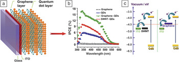
Inorganic quantum dot (QD) solar cells represent a promising photovoltaic technology because of their potential to exceed the Shockley–Queisser limit on single-junction energy extraction from the solar spectrum, their size-tunable photon absorption, and their efficient generation of multiple electron–hole pairs.Reference Kamat38 However, QD solar cells currently suffer from low photovoltaic efficiency because of poor electron–hole separation and deficient transfer of photogenerated electrons to electrodes. Although single-walled carbon nanotubes (SWNTs), stacked SWNTs with suitable energy levels, and one-dimensional nanostructures have been used as electron acceptors in QD solar cells to improve electron–hole separation, these devices still exhibited low incident photon-to-charge-carrier conversion efficiencies (IPCEs) of <5% and a photocurrent response of 4 A/m2 under 1000 W/m2 illumination.Reference Kamat38 Using graphene as a novel electron acceptor, Guo et al.Reference Guo, Yang, Sheng, Lu, Song and Li39 developed QD solar cells with the multilayered graphene–QD device structure and energy level alignment shown in Figure 2a and 2c, respectively. Owing to the high specific surface area, high mobility, and tunable bandgap of graphene, the resulting device exhibited an IPCE as high as 16% and a photoresponse of 10.8 A/m2 under 1000 W/m2 illumination (Figure 2b). This achievement represents significant progress in the development of high-performance QD solar cells. Further research efforts in this area could lead to even higher efficiencies.
(a) Schematic representation of a layered graphene–CdS quantum dot (QD) solar cell. (b) Incident photon-to-charge-carrier conversion efficiency (IPCE) curves of devices with different photoelectrodes. (c) Energy level diagrams of devices based on (right) graphene–QD solar cells and (left) single-walled carbon nanotube (SWNT)–QD solar cells. The red dotted line highlights the easier transfer of electrons to indium tin oxide (ITO) from graphene compared to that from nanotubes. Reproduced with permission from Reference Reference Guo, Yang, Sheng, Lu, Song and Li39. ©2010, Wiley.

Dye-sensitized solar cells containing graphene
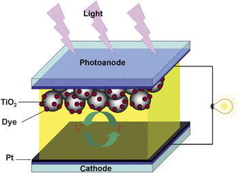
Dye-sensitized solar cells (DSSCs) represent a relatively new class of low-cost solar cells with great promise. As shown in Figure 3, a typical DSSC consists of a transparent cathode (e.g., fluorine-doped tin oxide [FTO]), a highly porous semiconductor (e.g., TiO2) layer with a soaked layer of dye (e.g., ruthenium polypyridine dye), an electrolyte solution containing redox pairs (e.g., iodide/triiodide), and a counter electrode (e.g., platinum). In operation, a dye molecule harvests sunlight and is excited to inject an electron directly into the conduction band of the TiO2. The injected electron then moves to the transparent anode and, through the external circuit, to the cathode (Figure 3). Meanwhile, the dye molecule strips one electron from iodine in the electrolyte by oxidizing it to triiodide. The triiodide then recovers its missing electron from the external circuit by diffusing to the counter electrode (i.e., cathode).Reference O’Regan and Grätzel40 The recently reported highest PCE for a DSSC is 12.3%.Reference Yella, Lee, Tsao, Yi, Chandiran, Nazeeruddin, Diau, Yeh, Zakeeruddin and Grätzel41 Although DSSCs are still not as efficient as silicon solar cells, their low cost and easy fabrication have made them very attractive for “low-density” applications, including rooftop solar collectors. As discussed in the remainder of this section, graphene has been used in almost every component of a DSSC.
Device structure of a dye-sensitized solar cell.

In view of the aforementioned high transparency and good conductivity intrinsically associated with graphene, several groups have applied graphene as a transparent cathode in DSSCs. For instance, Wang et al.Reference Wang, Zhi and Mullen42 processed solutions of reduced graphene oxide to deposit graphene films with a moderate conductivity of about 5.5 × 10⁴S/m and a high transmittance of 80%. They used these films as transparent electrodes in DSSCs that exhibited a lower PCE than achieved by an FTO-based device (0.26% for graphene film versus 0.84% for FTO).
The counter electrode of a DSSC catalyzes the reduction of redox pairs after electron injection. The state-of-the-art counter electrode, platinum, is very expensive. As alternatives, graphene-modified FTO and a graphene–conjugated polymer composite film have been used as counter electrodes to create DSSCs with iodine/triiodide redox pairs, providing performances better than unmodified FTO or bare polymer but still worse than that of platinum-coated FTO.Reference Lin, Huang, Liang and Wang43, Reference Xu, Bai, Lu, Li and Shi44 Recently, DSSCs with Co2+/3+ redox pairs were reported to exhibit a higher open-circuit voltage and a higher PCE than the iodine/triiodide counterpart with the same type of counter electrode. Kavan et al.Reference Kavan, Yum, Nazeeruddin and Grätzel45 found that, for Co2+/3+redox pairs, a graphene film on FTO exhibited higher electrocatalytic activity and higher device efficiency than a platinum–FTO electrode at high illumination intensity, indicating that graphene is an excellent counter electrode material for DSSCs.
The good conductivity of graphene can also be used to facilitate electron transport in porous TiO2 layers.Reference Yang, Zhai, Wang, Chen and Jiang46, Reference Tang, Lee, Xu, Liu, Chen, He, Cao, Yuan, Song, Chen, Luo, Chen, Zhang, Bello and Lee47 For example, incorporation of graphene into TiO2 layers was found to lead to a 45% increase in short-circuit current and a 39% increase in PCE due to lower recombination, faster electron transport, and higher light scattering.Reference Yang, Zhai, Wang, Chen and Jiang46 In addition, graphene quantum dots have been used as light absorbers in DSSCs.Reference Yan, Cui, Li and Li48
Fuel cells
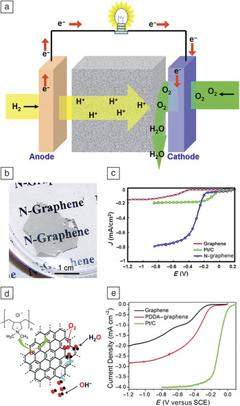
Fuel cells are considered to be one of the most efficient and environmentally benign energy-conversion technologies. Instead of burning fuel to create heat, fuel cells convert chemical energy directly into electricity, and with no moving parts, fuel cells produce no air pollution, hazardous wastes, or noise. As shown in Figure 4a, when hydrogen gas, for example, is pumped onto one electrode (the anode), the hydrogen is split into its constituent electrons and protons. The protons diffuse through the cell toward a second electrode (the cathode), whereas the electrons flow out of the anode to provide electrical power. Electrons and protons both end up at the cathode, where they combine with oxygen to form water.
(a) Schematic representation and working principle of a fuel cell. (b) Photograph of nitrogen-doped graphene obtained by chemical vapor deposition. (c) Voltammograms of the oxygen reduction reaction (ORR) in air-saturated 0.1 M KOH at a nitrogen-doped graphene electrode. Reproduced with permission from Reference Reference Qu, Liu, Baek and Dai10. ©2010, American Chemical Society. (d) Schematic illustration of the ORR catalyst based on poly(diallyldimethylammonium chloride) (PDDA) noncovalently functionalized graphene. (e) Voltammograms of the ORR on a PDDA–graphene electrode in O2-saturated 0.1 M KOH solution. Excellent ORR catalytic activity is reflected by both a small onset ORR potential and a large current density. SCE, saturated calomel electrode. Reproduced with permission from Reference Reference Wang, Yu, Dai, Chang and Baek62. ©2011, American Chemical Society.

The oxygen reduction reaction (ORR) can proceed either through a four-electron process that directly combines oxygen with electrons and protons to form water or through a less efficient two-step, two-electron pathway involving the formation of hydrogen peroxide ions as an intermediate.Reference Wang, Zhi and Mullen42 The ORR would naturally occur very slowly without a catalyst on the cathode. Platinum nanoparticles have long been regarded as the best catalyst for the ORR, although platinum-based electrodes suffer from a susceptibility to time-dependent drift and CO deactivation.Reference Ramani49 The high cost of platinum catalysts is also an obstacle to mass-market fuel cells for commercial applications. Indeed, the large-scale practical application of fuel cells has not been realized, even though alkaline fuel cells with platinum as an ORR electrocatalyst were developed for the Apollo lunar missions in the 1960s. Recent intensive research efforts to reduce or replace platinum-based electrodes in fuel cells have led to the development of new metal-free ORR electrocatalysts based on carbon nanomaterials. In particular, nitrogen-doped graphene was found to be a promising alternative metal-free ORR catalyst with a better electrocatalytic activity, longer operation stability, and greater tolerance to crossover of fuel from the opposite electrode than platinum.Reference Qu, Liu, Baek and Dai10
Fuel cells with graphene as the catalyst support
To improve the activity and efficiency of platinum catalysts, a widely used approach has been to immobilize platinum components on a highly conducting substrate that is inexpensive and has a high specific surface area.Reference Kou, Shao, Wang, Engelhard, Kwak, Wang, Viswanathan, Wang, Lin, Wang, Aksay and Liu50–Reference Dong, Gari, Li, Craig and Hou52 In this context, platinum nanoparticles supported on graphene sheets were found to exhibit a higher electrochemical surface area and ORR activity and better stability than the commercial platinum catalyst from the E-TEK division of BASF Fuel Cell.Reference Kou, Shao, Wang, Engelhard, Kwak, Wang, Viswanathan, Wang, Lin, Wang, Aksay and Liu50 The observed excellent ORR performance was attributed to the smaller size and reduced aggregation of platinum nanoparticles immobilized on the graphene sheets. Jafri et al.Reference Jafri, Rajalakshmi and Ramaprabhu51 used graphene nanoplatelets and nitrogen-doped graphene nanoplatelets as supports for platinum nanoparticles to construct proton-exchange membrane fuel cells with power densities of 4400 W/cm2 and 3900 W/cm2, respectively. The better performance of the nitrogen-doped graphene nanoplatelets was attributed to pyrrolic nitrogen defects (in which the nitrogen contributes two lone-pair electrons to the π system) acting as anchoring sites for carbon-catalyst binding and increasing electrical conductivity. To address the problem of CO deactivation of platinum catalysts, Dong et al.Reference Dong, Gari, Li, Craig and Hou52 developed graphene-supported platinum–ruthenium nanoparticles that also provide higher electrocatalytic performance with reduced overpotential and improved reversibility compared to graphite-supported alternatives.
Fuel cells with nitrogen-doped graphene as the metal-free catalyst
Apart from their use as catalyst supports, graphene and related materials have recently attracted significant attention as metal-free catalysts for fuel cells. For example, Gong et al.Reference Gong, Du, Xia, Durstock and Dai53 found that vertically aligned nitrogen-doped carbon nanotubes (VA-NCNTs) can effectively catalyze a four-electron ORR process with a much higher catalytic activity, lower overpotential, smaller crossover sensitivity, and better long-term operation stability than commercially available platinum/carbon black catalysts (brand name C2-20, 20% platinum on Vulcan XC-72R, E-TEK).Reference Gong, Du, Xia, Durstock and Dai53 The success of VA-NCNTs as ORR catalyst has motivated investigations of nitrogen-doped graphene for the same application.
According to quantum-mechanics calculations, carbon atoms adjacent to nitrogen dopants in VA-NCNTs have a relatively high positive charge density to counterbalance the strong electron affinity of the nitrogen atom. Nitrogen-induced charge delocalization can change the electrochemical potential and the chemisorption mode of O2 to weaken the oxygen–oxygen bonding, hence facilitating the ORR. Therefore, doping CNTs with nitrogen heteroatoms efficiently creates metal-free active sites for the electrochemical reduction of O2.Reference Gong, Du, Xia, Durstock and Dai53
Uncovering this new ORR mechanism for VA-NCNTs is important, as the same principle can be applied to other carbon nanomaterials (e.g., graphene). Indeed, nitrogen-doped graphene films produced by CVD in the presence of ammonia provide superb ORR performance, similar to that of VA-NCNTs at the same nitrogen content in alkaline medium (Figure 4b–c).Reference Qu, Liu, Baek and Dai10 Nitrogen-doped graphene samples synthesized by other approaches, including nitrogen plasma treatment of graphene,Reference Shao, Zhang, Engelhard, Li, Shao, Wang, Liu, Aksay and Lin54 edge functionalization of graphene,Reference Jeon, Yu, Bae, Choi, Chang, Dai and Baek55 thermal treatment of graphene with ammonia,Reference Geng, Chen, Chen, Li, Li, Sun, Ye and Knights56 and solvothermal treatment of graphene with tetrachloromethane and lithium nitride,Reference Deng, Pan, Yu, Cui, Jiang, Qi, Li, Fu, Ma, Xue, Sun and Bao57 also show good ORR electrocatalytic activities.
Recent work indicates that graphene and its derivatives doped with heteroatoms other than nitrogen could also exhibit improved ORR electrocatalytic activities, as exemplified by phosphorous-doped graphite layers,Reference Liu, Peng, Wang, Yu, Zheng and Yang58 boron-doped carbon nanotubes,Reference Yang, Jiang, Yu, Zhu, Chen, Wang, Wu, Ma, Ma and Hu59 and sulfur-doped graphene.Reference Yang, Yao, Li, Fang, Nie, Liu, Zhou, Chen and Huang60 More recently, Wang and co-workersReference Wang, Zhang, Xia, Roy, Chang, Baek and Dai61 successfully produced graphene codoped with nitrogen and boron (BCN graphene) by simply annealing graphene oxide in the presence of boric acid under ammonia and demonstrated significantly improved ORR electrocatalytic activity, even better than that of a commercial platinum/carbon electrode, resulting from a poorly understood synergistic effect associated with nitrogen and boron codoping of graphene.
Apart from such heteroatom-induced intramolecular charge transfer, charge transfer between molecules has also been demonstrated to impart ORR electrocatalytic activity to graphene. In particular, graphene functionalized with poly(diallyldimethylammonium chloride) (PDDA) was reported to exhibit good ORR electrocatalytic activity (Figure 4d–e) resulting from charge transfer between the N-free graphene and PDDA. Such intermolecular charge transfer provides a simple, low-cost approach to develop carbon-based metal-free ORR catalysts. Continued research in this nascent field could give rise to a flourishing advanced energy-conversion technology based on graphene materials.
Graphene for energy storage
Along with energy conversion, energy storage (as in supercapacitors and batteries) is also of paramount importance, especially for mobile applications. For many practical applications, high energy-storage capability, high power-delivery capability, and long cycle life are necessary. Owing to the unique characteristics of graphene, much effort has been devoted to applications of graphene in high-performance supercapacitors and batteries.
Supercapacitors
Supercapacitors are electrochemical devices that can store energy and release it with high power capability and high current density within a short time interval.Reference Zhang and Zhao63 Thus, supercapacitors are considered to be the perfect complement for batteries or fuel cells in various applications, such as automobiles and high-performance portable electronics. The principle of energy storage in a supercapacitor is either (1) electrostatic charge accumulation on the electrode–electrolyte interface (electric double-layer capacitance) or (2) transfer of charge to the layer of redox molecules on the surface of the electrode (pseudocapacitance). In practical supercapacitors, the two storage mechanisms often work simultaneously.Reference Conway, Birss and Wojtowicz64 Electrode materials intensively studied for supercapacitors include carbon,Reference Frackowiak and Beguin65 metal oxides,Reference Zheng, Cygan and Jow66 and conducting polymers,Reference Rudge, Davey, Raistrick, Gottesfeld and Ferraris67 with a recent focus on CNTs and graphene.
Supercapacitors with graphene electrodes
The electric double-layer capacitance is proportional to the effective specific surface area of an electrode material. Therefore, graphene, with a theoretical specific surface area of 2.63 × 10⁶ m2/kg, together with good conductivity, controllable microstructure, and excellent thermal/mechanical stability, is promising for supercapacitor electrodes.Reference Stoller, Park, Zhu, An and Ruoff68–Reference Wang, Shi, Huang, Ma, Wang, Chen and Chen71 Using a chemically reduced graphene oxide electrode, Stoller et al.Reference Stoller, Park, Zhu, An and Ruoff68, Reference Zhu, Murali, Stoller, Velamakanni, Piner and Ruoff69 obtained specific capacitances of 135,000 F/kg and 99,000 F/kg in aqueous and organic electrolytes, respectively. They also obtained capacitance values of 191,000 F/kg and 120,000 F/kg in organic electrolytes for reduced graphene oxides produced using simple microwave heating and propylene carbonate solution reduction, respectively. On the other hand, Wang et al.Reference Wang, Shi, Huang, Ma, Wang, Chen and Chen71 reported graphene-based supercapacitors with a maximum specific capacitance of 205,000 F/kg at a power density of 10 kW/kg and an energy density of 28.5 W h/kg that also had an excellent cyclic lifetime, retaining 90% of the initial capacitance after 1200 cycles.
Supercapacitors with carbon nanotube and graphene hybrid electrodes
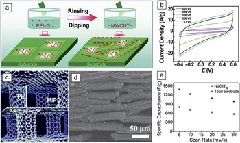
Hybrid electrodes based on two-dimensional graphene and one-dimensional carbon nanotubes (CNTs) are of great interest because their structure at the nanometer to micrometer scale can be well controlled for supercapacitor applications.Reference Yu and Dai72–Reference Du, Yu, Dai, Ganguli, Varshney and Roy74 For instance, a solution layer-by-layer self-assembly approach (Figure 5a–b) was used to prepare multilayered hybrid carbon films of poly(ethyleneimine)-modified graphene sheets and acid-oxidized multiwalled CNTs to construct supercapacitors with an average specific capacitance of 120,000 F/kg.Reference Yu and Dai72
(a) Schematic illustration of the preparation of multilayered graphene–multiwalled carbon nanotube (MWCNT) hybrid electrodes for supercapacitors. PEI–G, poly(ethyleneimine)-modified graphene. (b) Cyclic voltammograms from the graphene–MWCNT hybrid electrode in 1.0 M H2SO4 solution. Parts (a) and (b) reproduced with permission from Reference Reference Yu and Dai72. ©2010, American Chemical Society. (c) Schematic illustration and (d) typical scanning electron microscopy image of a three-dimensional pillared vertically aligned carbon nanotube (VA-CNT)–graphene nanostructure. In (c), the dimensions of interest are the pillar length (PL) and the minimum interpillar distance (MIPD). (e) Average specific capacitance of a Ni(OH)2-coated VA-CNT–graphene pillared electrode at various scan rates. Parts (c)–(e) reproduced with permission from Reference Reference Du, Yu, Dai, Ganguli, Varshney and Roy74. ©2011, American Chemical Society.

Similarly, the inherently nanoporous three-dimensional pillared vertically aligned carbon nanotube (VA-CNT)–graphene hybrid architecture with a large surface area (Figure 5c) should allow the selection of specific thermal, mechanical, and electrical properties that are useful for many potential applications, including supercapacitors.Reference Conway, Birss and Wojtowicz64 To test this possibility, Feng et al.Reference Du, Yu, Dai, Ganguli, Varshney and Roy74 prepared a VA-CNT–graphene hybrid by the intercalated growth of VA-CNTs into thermally expanded highly ordered pyrolytic graphite (Figure 5d). The resulting VA-CNT–graphene hybridized with a nickel hydroxide coating indeed showed a high specific capacitance with an impressive charging-rate capability (Figure 5e).
Lithium-ion batteries
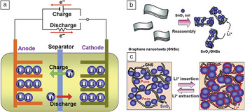
Lithium-ion batteries are regarded as highly attractive rechargable batteries because of their low weight and high energy-storage capacity. Typically, a lithium-ion battery is composed of a lithium intercalation anode and cathode and an electrolyte (Figure 6a). The nature and microstructure of the electrode materials are crucial not only for energy and power density but also for battery safety and cycle lifetime.Reference Liang and Zhi75, Reference Zhou, Wang, Li, Zhang, Li, Wu, Wen, Lu and Cheng76 Current electrode materials, including carbon black and nanofibers, graphite, silicon, metals, and metal oxides, suffer from poor electrical conductivity and/or huge volume changes during charging/discharging.Reference Liang and Zhi75, Reference Zhou, Wang, Li, Zhang, Li, Wu, Wen, Lu and Cheng76
Schematic representations of (a) the working principle of a lithium-ion battery, (b) the structure and synthesis of a graphene–SnO2 electrode, and (c) the improved lithium-ion storage–release cyclability of the graphene–SnO2 electrode. The nanoporous structure with SnO2 nanoparticles confined by graphene sheets limits the volume expansion upon lithium insertion and improves cyclic performance. Reproduced with permission from Reference Reference Paek, Yoo and Honma83. ©2009, American Chemical Society.

Lithium-ion batteries with graphene electrodes
Compared with the widely used graphite electrode, graphene has a larger specific surface area and twice the lithium storage capacity.Reference Wang, Wang, Wang, Park, Dou, Ahn and Kim77 Moreover, recent work indicated that the graphene two-dimensional edge plane site could aid lithium-ion adsorption and diffusion, leading to a reduced charging time and an increased power output.Reference Pan, Wang, Zhao, Wu, Zhang, Wang and Jiao78 The nanosized holes in graphene sheets were also found to be reponsible for the high-rate discharge capability of lithium-ion battery anodes.Reference Takamura, Endo, Fu, Wu, Lee and Matsumoto79 Indeed, Pan et al.Reference Pan, Wang, Zhao, Wu, Zhang, Wang and Jiao78 employed graphene-sheet-based electrodes in lithium-ion batterries and achieved a capacity of 540 A h/kg, which is higher than that of graphite. When carbon nanotubes and fullerenes were used as spacers to prevent individual graphene sheets from restacking, the capacity of the graphene electrodes could be further increased to 730 A h/kg and 784 A h/kg, respectively.Reference Yoo, Kim, Hosono, Zhou, Kudo and Honma80
Wu et al.Reference Wu, Ren, Xu, Li and Cheng81 used nitrogen- or boron-doped graphene to realize simultaneous high power and energy densities. The superior performance came from rapid surface Li+ absorption, ultrafast Li+diffusion and electron transport, increased intersheet distance, and improved electrical conductivity because of the two-dimensional structure, disordered surface morphology, heteroatomic defects, and better electrode/electrolyte wettability of the doped graphene. However, it should be noted that graphene as a lithium-ion battery electrode still suffers from irreversible reactions with lithium and solid electrolyte interface formation, resulting in irreversible performance.Reference Su and Schlogl82
Lithium-ion batteries with graphene hybrid electrodes
To address the issues discussed in the preceding subsection and to utilize the high lithium-ion reversible storage capacity of metals and metal oxides, graphene electrodes hybridized with certain metal or metal-oxide nanoparticles have been prepared to exhibit improved performance.Reference Paek, Yoo and Honma83–Reference Chou, Wang, Choucair, Liu, Stride and Dou86 For example, an electrode made of nanoporous graphene sheets decorated with loosely packed SnO2 nanoparticles (Figure 6b–c) was found to exhibit a reversible capacity of 810 A h/kg with a much improved reversible cycling performance compared to those of bare graphene, SnO2 nanoparticle, and bare graphite electrodes.Reference Paek, Yoo and Honma83 Other metal oxides, such as Co3O4, Fe2O3, TiO2, and SiO2have also been used to functionalize graphene for use as electrodes in high-performance lithium-ion batteries.Reference Wu, Ren, Wen, Gao, Zhao, Chen, Zhou, Li and Cheng84–Reference Chou, Wang, Choucair, Liu, Stride and Dou86
Concluding remarks
As discussed herein, the intensive study of graphene materials with unique structures and properties offers a great opportunity to meet the challenges of energy conversion and storage. This article presented a critical and concise review of the recent progress in this active emerging area. Even this brief review reveals the versatility of graphene, with and without functionalization, for improving the performance of various energy-conversion (e.g., solar cells, fuel cells) and -storage (e.g., supercapacitors, batteries) devices. Before these materials can be widely adopted, important hurdles must be surmounted, such as processability, scalability, energy capacity, rate capability, and cost effectiveness. However, judicious application of various physicochemical approaches to the development of graphene materials with tailor-made microstructures and electrochemical properties for the technological marketplace could lead to a wide range of important uses for graphene materials in high-performance energy-conversion and -storage devices.
Acknowledgments
The authors are grateful for the financial support from AFOSR (FA9550-12-1-0069, FA9550-09-1-0331, FA9550-10-1-0546, FA8650-07-D-5800, FA2386-10-1-4071, TSI-2356-10-81529, AOARD-104055), DOD-AFOSR-MURI (FA9550-12-1-0037), AFRL/UTC (11-S587-1000-01-C1), AFRL/DAGSI (RX2-CWRU-10-1), US AFOSR-Korea NBIT, US Army (W911NF-11-1-0209), NSF (CMMI-1000768, CMMI-1047655, DMR-1106160), and DOE (DE-SC0003736).