Introduction
A carbon nanotube (CNT) is a unique pseudo-one-dimensional structure composed of one or more layers of graphitic sp 2-hybridized carbon and is a representative material for nanotechnology. The initial report of the discovery and elucidation of the structure of CNTs by S. Iijima has been cited more than 28,000 times (as of September 2017, according to the Web of Science), and was ranked among the top 100 (at #36) most highly cited scientific papers in 2014. Reference Iijima1,Reference Van Noorden, Maher and Nuzzo2 CNTs possess diameters less than 100 nm for multiwall CNTs (MWCNTs) and generally less than ∼3 nm for single-wall CNTs (SWCNTs) and can have exceptionally high-aspect ratios as their lengths extend into the centimeter scale. Reference Zhang, Zhang, Zhang, Xie, Qian and Wei3 Importantly, being completely composed of carbon where the location of each atom is precisely defined, CNTs have exceptionally low density (e.g., 1.3 g/cm3, one-half that of aluminum) and possess a Young’s modulus as high as 3.7 TPa, which is about 5× that of carbon fibers. Reference Treacy, Ebbesen and Gibson4
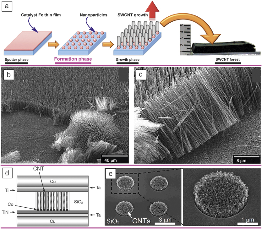
Vertically aligned CNT arrays ( Figure 1a), Reference Chen, Futaba, Kimura, Sakurai, Yumura and Hata5 called “VANTAs” for short or “forests,” or “carpets” are unique and interesting CNT assemblies, grown from well-defined arrays of catalyst nanoparticles on substrates by chemical vapor deposition (CVD). The alignment stems from crowding among CNTs, which then vertically orients the growth. Reference Li, Xie, Qian, Chang, Zou, Zhou, Zhao and Wang6–Reference Xu, Futaba, Yumura and Hata8 CNT forests possess a number of merits. First, since the growth is carried out from surface-bound catalysts, the catalysts can remain in the growth-step of the CVD process for arbitrarily long periods (up to ∼30 h) Reference Zhong, Iwasaki, Robertson and Kawarada9 to increase the CNT length, in contrast to other synthesis methods, such as arc discharge Reference Journet, Maser, Bernier, Loiseau, de la Chapelle, Lefrant, Deniard, Lee and Fischer10 and laser ablation, Reference Guo, Nikolaev, Thess, Colbert and Smalley11 where the growth time is fundamentally limited. Second, in many cases, the catalysts remain anchored to the surface during growth (called “root growth”), Reference Liu, Jiang, Feng, Chen and Fan12–Reference Puretzky, Eres, Rouleau, Ivanov and Geohegan15 and the CNT forest can be separated from the catalyst and substrate to yield high-purity, catalyst-free CNT material. Reference Hata, Futaba, Mizuno, Namai, Yumura and Iijima16 These features have proven important for applications.
(a) Schematic of the synthesis of carbon nanotube (CNT) forests. Reference Chen, Futaba, Kimura, Sakurai, Yumura and Hata5 Units for the ruler are millimeters. (b–c) Scanning electron microscope (SEM) images of CNT forests. Reprinted with permission from Reference Ren, Huang, Xu, Wang, Bush, Siegal and ProvencioReference 35. © 1998 AAAS. (d) Schematic of CNT via structure and (e) low and high magnification SEM images of CNT bundles grown in via holes (left and right, respectively). Reprinted with permission from Reference Katagiri, Sakuma, Suzuki, Sakai, Sato, Hyakushima, Nihei and AwanoReference 36. © 2008 The Japan Society of Applied Physics. Note: SWCNT, single-wall carbon nanotube.

The growth process for CNT forests is scalable and industrial processes have been developed to mass produce CNT forests leading to numerous CNT applications, some of which have been commercialized, spanning CNT touch screens, Reference Feng, Liu, Wu, Liu, Cheng, Zhang, Sun, Li, Fan and Jiang17 thermal interface materials (TIMs), Reference Huang, Liu, Wu and Fan18 field emitters, Reference Choi, Chung, Kang, Kim, Jin, Han, Lee, Jung, Lee, Park and Kim19,Reference Chen, Shin, Iwasaki, Kawarada and Lee20 planar incandescent light sources, Reference Zhang, Fang, Zakhidov, Lee, Aliev, Williams, Atkinson and Baughman21 flexible charge collectors, Reference Di, Hu, Chen, Yong, Chen, Feng, Zhu and Li22 high-power and high-density supercapacitors, Reference Lu, Qu, Henry and Dai23,Reference Jiang, Wang, Zang, Yang, Kozinda and Lin24 gecko-foot-mimetic dry adhesives, Reference Qu, Dai, Stone, Xia and Wang25 bristles/brushes, Reference Cao, Veedu, Li, Yao, Ghasemi-Nejhad and Ajayan26,Reference Toth, Maklin, Halonen, Palosaari, Juuti, Jantunen, Kordas, Sawyer, Vajtai and Ajayan27 through-silicon vertical interconnect access (vias), Reference Xie, Zhang, van der Veen, Arstila, Hantschel, Chen, Zhong and Robertson28 and high current-carrying capacity CNT-Cu composites. Reference Subramaniam, Yamada, Kobashi, Sekiguchi, Futaba, Yumura and Hata29
For example, Foxconn Electronics, in collaboration with Tsinghua University, China, fabricated ultrathin and aligned CNT sheets from superaligned MWCNT forests on 8-in. (200-mm) silicon wafers. These sheets have been used for transparent conducting films in smartphone touch screens. Reference Feng, Liu, Wu, Liu, Cheng, Zhang, Sun, Li, Fan and Jiang17,Reference Jiang, Wang, Li, Liu, Liu and Fan30,Reference Liu, Wei, Liu, Liu, Jiang and Fan31 In addition, the National Institute of Advanced Industrial Science and Technology (AIST), Japan, in collaboration with Zeon Corporation, developed a continuous, belt conveyor process to synthesize aligned SWCNTs on flat 50 cm × 50 cm metal substrates and realized metric ton-level production of a high surface area material composed of long and pure SWCNTs. Reference Hata32 These SWCNTs have been used to produce TIM sheets with excellent thermal resistance (0.05°C/W), lower than that of thermal grease (0.10°C/W). 33 Further, the growth of forests is not limited to flat substrates and can be extended to three dimensions. Wei et al. demonstrated a potentially unlimited production capacity by growing forests on bead substrates using the fluidized bed CVD process. Reference Zhang, Zhao, Huang, Nie and Wei34
This article presents a general picture of the development of CNT forest research, drawing on groundbreaking milestones, aspects of controlled synthesis, advances in material processing, and the essential requirements for CNT forest synthesis.
Overview of CNT forest research
Inception
Li et al. first reported the synthesis of a vertically aligned CNT forest in 1996, where a 50-μm-tall forest of 30-nm dia. MWCNTs was grown by CVD using acetylene at 700°C from iron catalyst nanoparticles embedded in a mesoporous silica substrate. Reference Li, Xie, Qian, Chang, Zou, Zhou, Zhao and Wang6 This pioneering work marked an impetus for researchers to investigate challenges surrounding the synthesis as well as application potential of this material.
Low-temperature synthesis
One of the initial challenges was to reduce the CVD temperatures to enable synthesis directly onto devices. Ren et al. used plasma-enhanced hot filament CVD in 1998 to synthesize MWCNT forests with heights from 0.1–50 μm and controllable diameters (20–400 nm) on glass substrates at temperatures below 666°C (Figure 1b–c). Reference Ren, Huang, Xu, Wang, Bush, Siegal and Provencio35 Research groups led by Awano at Fujitsu Laboratories Ltd. and Robertson at the University of Cambridge demonstrated further advancements in growing CNT forests below 400°C to integrate forests into the back-end-of-line of large-scale integration (LSI) for use in CNT vias (Figure 1d–e). Reference Katagiri, Sakuma, Suzuki, Sakai, Sato, Hyakushima, Nihei and Awano36,Reference Cantoro, Hofmann, Pisana, Scardaci, Parvez, Ducati, Ferrari, Blackburn, Wang and Robertson37 Conventional copper LSI vias made by the dual-damascene process were expected to fail after miniaturization to the 22-nm node due to fundamental electromigration limitations. Awano et al. used remote plasma CVD and demonstrated forest growth in vias at temperatures as low as 430°C to overcome this obstacle. Reference Katagiri, Sakuma, Suzuki, Sakai, Sato, Hyakushima, Nihei and Awano36 Robertson et al. demonstrated the synthesis of SWCNT forests with narrow diameter distribution at 350°C by a cold-wall CVD process using NH3 and H2 to facilitate catalyst nanostructuring and activation. Reference Cantoro, Hofmann, Pisana, Scardaci, Parvez, Ducati, Ferrari, Blackburn, Wang and Robertson37 Hart et al. later demonstrated an alternative approach to reduce the process temperature to 500°C by preheating the reactive gases. Reference Nessim, Seita, OʼBrien, Hart, Bonaparte, Mitchell and Thompson38 Recent research has shown that low-temperature synthesis leads to defective CNTs, and therefore, the integration of highly crystalline CNTs into devices remains a challenge. Reference Katagiri, Sakuma, Yamazaki, Suzuki, Sato, Nihei, Sakai and Awano39,Reference Kimura, Futaba, Yumura and Hata40
CNT forest patterning
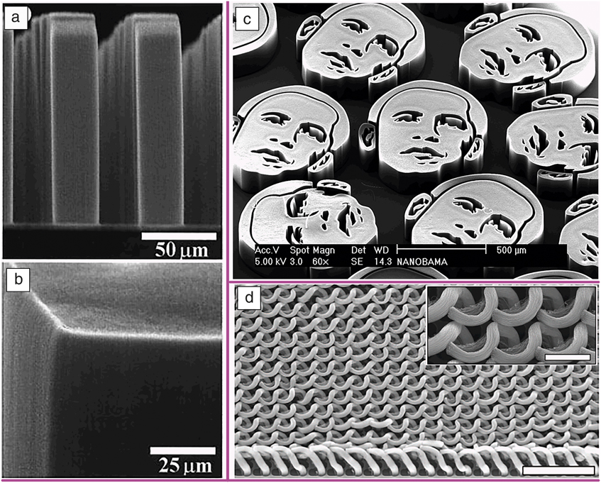
Dai et al. demonstrated in 1999 that regular arrays of CNT forests (10–250 μm in size at pitches of 50–200 μm) could be synthesized using thermal CVD at 700°C by simply patterning the catalyst ( Figure 2a–b). Reference Fan, Chapline, Franklin, Tombler, Cassell and Dai7 Additionally, they showed that these arrays could function as low-operating-voltage field emitters. Nilsson et al. later reported the relationship between emitter (CNT) spacing and field-emission properties. Reference Nilsson, Groening, Emmenegger, Kuettel, Schaller, Schlapbach, Kind, Bonard and Kern41 These pioneering studies sparked an enormous research effort to develop CNT field-emission displays led by two companies, Samsung and Noritake Co., Ltd. Reference Choi, Chung, Kang, Kim, Jin, Han, Lee, Jung, Lee, Park and Kim19,Reference Kim, Choi, Lee and Jung42,Reference Kurachi, Uemura, Yotani, Nagasako, Yamada, Ezaki, Maesoba, Nakao, Ito, Sakurai, Saito and Shinohara43 Currently, work on field emission from CNTs is ongoing, but significantly less for display applications as it has given way to the fast development of competing technology (e.g., organic light-emitting diodes). In fact, many companies have slowed or completely halted field-emission display development. 44
(a) Scanning electron microscope (SEM) image of carbon nanotube forest arrays. (b) SEM image showing sharp edges and corners. Reprinted with permission from Reference Fan, Chapline, Franklin, Tombler, Cassell and DaiReference 7. © 1999 AAAS. (c) Microminiature portraits of then-President-Elect of the United States, Barack Obama (NANOBAMA). Courtesy of J. Hart. (d) Complex microstructures. Scale bar = 40 μm. Inset: a close-up SEM image. Scale bar = 10 μm. Reprinted with permission from Reference De Volder, Park, Tawfick and HartReference 52. © 2014 Macmillan Publishers Ltd.
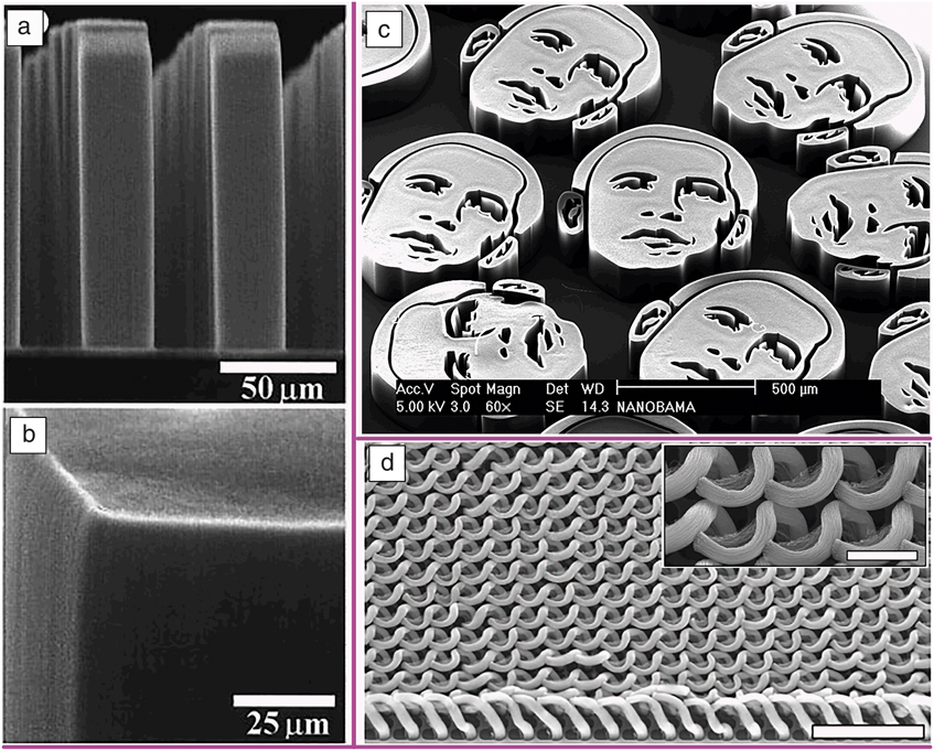
Dai et al. showed in their initial work that the synthesis of high-aspect-ratio and self-oriented arrays grown normal to the substrate by the self-assembly of CNTs was possible. Furthermore, these structures could be uniform in shape with sharp, well-defined edges, precisely matching the catalyst pattern throughout its length. Reference Fan, Chapline, Franklin, Tombler, Cassell and Dai7 Beautiful and complex structures could also be fabricated by utilizing lithography. Ajayan et al. pursued this aspect of making complex structures by simultaneously synthesizing laterally and vertically oriented forests from the sides and top, respectively, of trenches and demonstrating a flower-like structure grown from a silica pole. Reference Wei, Vajtai, Jung, Ward, Zhang, Ramanath and Ajayan45 J. Hart famously drew a 500-μm-wide image (NANOBAMA) in 2008 of the then-president-elect of the United States (Figure 2c). 46
Engineering complex CNT forest structures
The structure of a CNT forest can also be engineered to control its density, orientation, and shape, opening up new application areas, such as supercapacitors and microelectromechanical systems. As grown, the CNT forests have a low mass density (0.037 g/cm3) and high porosity (∼96%). Reference Futaba, Hata, Namai, Yamada, Mizuno, Hayamizu, Yumura and Iijima47 Futaba et al. found that the CNT forest could form a packed, highly dense (0.57 g/cm3), and aligned solid by immersing the forest into a liquid and allowing capillary forces to draw the CNTs together. Reference Futaba, Hata, Yamada, Hiraoka, Hayamizu, Kakudate, Tanaike, Hatori, Yumura and Iijima48 In addition, by applying external forces, the forests could be reoriented into a laterally aligned sheet for supercapacitor electrodes. This approach has been expanded by various methods, such as controlling the capillary force, multistep lithography, and controlling the strain during growth to fabricate diverse three-dimensional (3D) structures (Figure 2d), spanning supercapacitors, cantilevers, relays, switches, and field-effect transistors. Reference Hayamizu, Yamada, Mizuno, Davis, Futaba, Yumura and Hata49–Reference De Volder, Park, Tawfick and Hart52 The state of the art of this technique is exemplified by an all-CNT 3D relay composed of a suspended cantilever, gate, and drain electrodes. Reference Hayamizu, Yamada, Mizuno, Davis, Futaba, Yumura and Hata49
Drawing fibers and sheets
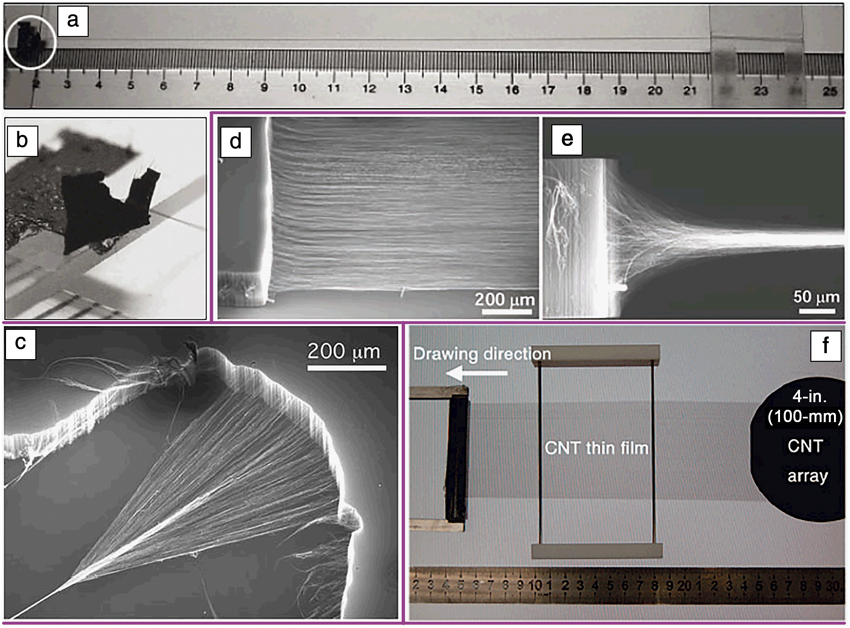
CNTs within a forest are not isolated, but rather, are interconnected through intermittent contact with adjacent CNTs, due to the self-assembly necessary for vertical alignment. This interconnection allows for a unique structural transformation of the forest into a fiber or aligned sheet. Jiang et al. were pioneers in this field where, in 2002, they reported that one could continuously draw bundles of CNTs into a fiber from a superaligned MWCNT forest ( Figure 3a–b), analogous to drawing a thread from silk. Reference Jiang, Li and Fan53 Baughman et al. further improved this drawing process by adding a simultaneous twist and demonstrated mechanically robust CNT yarn that did not degrade in strength when knotted, such as conventional fibers (Figure 3c). Reference Zhang, Atkinson and Baughman54 He later demonstrated that CNTs could be drawn out one-dimensionally from the side of the forest to fabricate transparent, freestanding MWCNT sheets (Figure 3d–e). Reference Zhang, Fang, Zakhidov, Lee, Aliev, Williams, Atkinson and Baughman21 These thin sheets (∼50-nm-thick, sheet resistance of ∼700 Ω/□ in the draw direction; transmittance of >85%) could therefore potentially serve as transparent conductors as touchscreens require sheet resistance of less than 500 Ω/□ and a transmittance greater than 85%. Jiang et al. developed this technique into a roll-to-roll process to produce transparent conducting films adequate for touch panels (sheet resistance of 208 Ω/□ with a transmittance of 90%) (Figure 3f). Reference Feng, Liu, Wu, Liu, Cheng, Zhang, Sun, Li, Fan and Jiang17,Reference Xiao, Chen, Feng, Liu, Bai, Wang, Qian, Zhang, Li, Jiang and Fan55 Foxconn Electronics (Hon Hai Precision Industry, China) uses this technology in some smartphones. Reference Zhou and Azumi56
(a) 30-cm long carbon nanotube (CNT) yarn drawn from a 100-μm-tall, freestanding CNT forest. Units for the ruler are centimeters. (b) Enlarged photograph of the forest. Reprinted with permission from Reference Jiang, Li and FanReference 53. © 2002 Macmillan Publishers Ltd. (c) Scanning electron microscope (SEM) image of the draw and twist process from a CNT forest. Reprinted with permission from Reference Zhang, Atkinson and BaughmanReference 54. © 2004 AAAS. SEM images of a multiwall CNT (MWCNT) forest transformation into sheets viewed (d) at 35° angle with respect to the forest plane and (e) from the side. Reprinted with permission from Reference Zhang, Fang, Zakhidov, Lee, Aliev, Williams, Atkinson and BaughmanReference 21. © 2005 AAAS. (f) Freestanding CNT film drawn out from a superaligned MWCNT array grown on a 4-in. (100-mm) silicon wafer. Units for the ruler are centimeters. Reprinted with permission from Reference Xiao, Chen, Feng, Liu, Bai, Wang, Qian, Zhang, Li, Jiang and FanReference 55. © 2008 American Chemical Society.

An alternative approach to fabricate CNT thin films from forests is to grow them vertically from catalyst lines, lay them horizontally onto a substrate, and solidify them through liquid-induced densification. When strained, these thin and aligned CNT films fractured into islands, however, they remained interconnected through CNT bundles in a manner similar to peeled string cheese. This phenomenon was used to develop a band-aid-type strain sensor suitable for monitoring a wide range of human motions by affixing the sensor onto skin. Reference Yamada, Hayamizu, Yamamoto, Yomogida, Izadi-Najafabadi, Futaba and Hata57
SWCNT forests
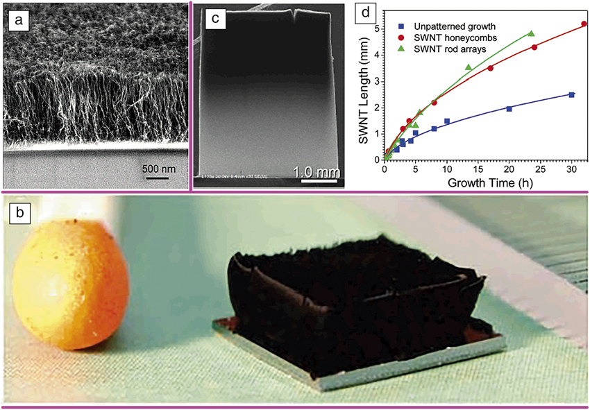
All of the early studies on CNT forests involved MWCNTs. Almost a decade passed before a process was developed that could grow a forest of SWCNTs. To achieve this, it was necessary to develop a method to prepare an array of small catalyst nanoparticles and a special CVD process, both suited for SWCNT growth. Maruyama et al. reported the first pioneering work using monodispersed Co-Mo catalyst nanoparticles on quartz substrates and alcohol as the carbon feedstock to grow a 1.5-μm-tall forest in 60 min ( Figure 4a). Reference Murakami, Chiashi, Miyauchi, Hu, Ogura, Okubo and Maruyama58 Alcohol was important for high catalyst activity and long lifetime. The long lifetime was attributed to the etching of carbon atoms with dangling bonds by the decomposed OH radical. Reference Maruyama, Kojima, Miyauchi, Chiashi and Kohno59 Hata and Futaba et al. reported a water-assisted CVD technique on an alumina-Fe catalyst system to grow mm-scale (2.5 mm, 10 min) SWCNT forests (Figure 4b). Reference Hata, Futaba, Mizuno, Namai, Yumura and Iijima16 These SWCNT forests could be easily separated from the substrate and catalyst, providing an extremely pure SWCNT material (>99.98%) Reference Hata, Futaba, Mizuno, Namai, Yumura and Iijima16 with high specific surface area (>1100 m2/g). Reference Futaba, Goto, Yamada, Yasuda, Yumura and Hata60,Reference Chen, Sakurai, Yumura, Hata and Futaba61 The long length and high purity were crucial and significant advantages for the development of applications. Reference Izadi-Najafabadi, Yasuda, Kobashi, Yamada, Futaba, Hatori, Yumura, Iijima and Hata62,Reference Ata, Kobashi, Yumura and Hata63 Currently, Zeon Corporation is producing metric ton-scale SWCNT forests per year, 64 under the subsidiary Zeon Nano Technology Co., Ltd., based on this synthesis technique and is developing applications spanning energy storage (e.g., supercapacitor electrodes), electronics (e.g., thermal interface materials for the heat management of servers and power devices), and functional materials (e.g., high-temperature tolerant rubber composites, electrically conductive rubbers and paints, and antistatic plastics). 33,Reference Izadi-Najafabadi, Yasuda, Kobashi, Yamada, Futaba, Hatori, Yumura, Iijima and Hata62,Reference Ata, Kobashi, Yumura and Hata63,65 Subsequent studies have shown that SWCNT forests can be grown with long lifetimes of up to ∼30 h and forest heights beyond 0.5 cm (Figure 4c–d). Reference Zhong, Iwasaki, Robertson and Kawarada9
(a) Scanning electron microscope (SEM) image of vertically aligned single-wall carbon nanotube (SWCNT) forests grown using alcohol chemical vapor deposition (CVD). Reprinted with permission from Reference Murakami, Chiashi, Miyauchi, Hu, Ogura, Okubo and MaruyamaReference 58. © 2004 Elsevier. (b) Picture of a 2.5-mm-tall SWCNT forest grown using water-assisted CVD and the head of a match. Reference Hata, Futaba, Mizuno, Namai, Yumura and Iijima16 (c) SEM image of a half-centimeter high vertically aligned SWCNT forests. (d) Time evolution of the growth of SWCNTs on different types of substrates highlighting the long catalyst lifetime. Note: units = h. Reprinted with permission from Reference Zhong, Iwasaki, Robertson and KawaradaReference 9. © 2007 American Chemical Society.

Requirements for the synthesis of CNT forests
Catalyst size and spacing
The catalyst is one of the primary factors in CNT forest synthesis. Because the synthesis of a CNT forest requires an array of catalyst nanoparticles on a substrate, the catalyst size and spacing are important parameters. Many studies have proven that for most CVD conditions, the catalyst size determines the nanotube diameter and the number of walls, where a small catalyst produces a small diameter SWCNT and the number of walls increases with catalyst size. Reference Cheung, Kurtz, Park and Lieber66–Reference Yamada, Namai, Hata, Futaba, Mizuno, Fan, Yudasaka, Yumura and Iijima69 This relationship has been used to modulate the CNT diameter and its number of walls within the forest. In addition, the catalyst spacing determines the interaction between the CNTs and thus is strongly correlated to the ability to self-assemble. This is particularly true for SWCNTs, as they cannot individually stand vertically and require the support of adjacent SWCNTs for vertical alignment. Reference Xu, Futaba, Yumura and Hata8
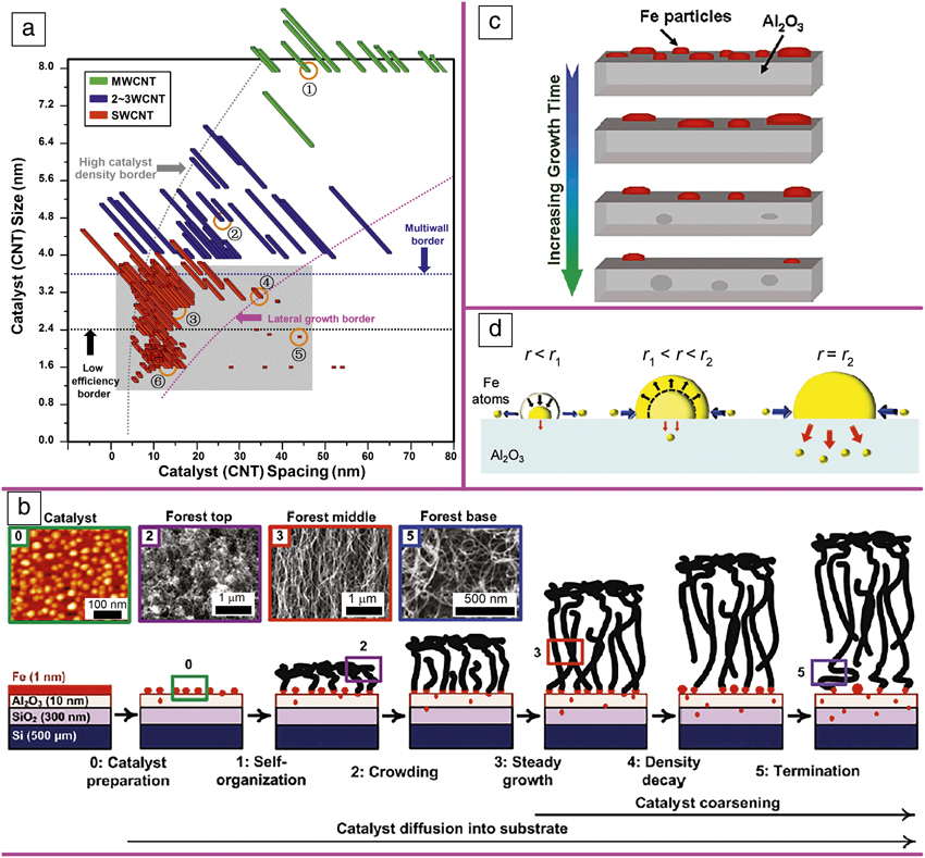
A systematic investigation of synthesis of CNT forests to determine relationships between catalyst size and the spacing, forest height, and number of walls in the CNTs was carried out and mapped (catalyst size: 1.3–8.0 nm; spacing: 5–80 nm). Reference Chen, Davis, Futaba, Sakurai, Kobashi, Yumura and Hata70 This map revealed the existence of a “sweet spot” for the highly efficient growth of SWCNT forests ( Figure 5a). SWCNT forests could only be grown efficiently within this region because (1) increased catalyst particle diameter would lead to MWCNTs growth (multiwall border); (2) decreased diameter would lead to low growth rates (low-efficiency border); (3) large catalyst spacing would lead to the inability to vertically align (lateral growth border); Reference Bedewy, Meshot, Reinker and Hart71,Reference Bedewy and Hart72 and (4) tightly spaced catalysts are difficult to prepare (high catalyst density border).
(a) Map showing the multiple borders and zones enclosing the high-efficiency single-wall carbon nanotube (SWCNT) region (3) as a function of catalyst (CNT) size and spacing. (1) Multiwall carbon nanotube (MWCNT) forest region; (2) two- to three-wall CNT forest region; (4) nonaligned (low-density) CNT forest region; (5) lateral SWCNT agglomerate region; and (6) low-efficiency short SWCNT forest region. Reference Chen, Davis, Futaba, Sakurai, Kobashi, Yumura and Hata70 (b) Collective model of catalyst evolution and CNT population dynamics, showing five distinct stages of the forest growth process. Stage 1: lateral entanglement of CNTs at the onset of growth; Stage 2: beginning of vertical growth; Stage 3: continued vertical forest growth; Stage 4: forest growth rate decrease due to loss in active catalyst nanoparticles; Stage 5: forest growth stops. Reprinted with permission from Reference Bedewy, Meshot, Reinker and HartReference 71. © 2011 American Chemical Society. (c) Schematic diagram showing (top to bottom) the loss of Fe catalyst due to the combination of Ostwald ripening and subsurface diffusion. Reprinted with permission from Reference Kim, Pint, Amama, Zakharov, Hauge, Maruyama and StachReference 76. © 2010 American Chemical Society. (d) Fe catalyst nanoparticle size stability driven by Ostwald ripening and subsurface diffusion competition. Left/middle: decrease/increase in particle size by Ostwald ripening. Right: stable particle size due to the balance between the two mechanisms. Reference Sakurai, Nishino, Futaba, Yasuda, Yamada, Maigne, Matsuo, Nakamura, Yumura and Hata77 Note: r, catalyst nanoparticle radius; r 1, smaller, unstable equilibrium particle radius; r 2, larger, stable equilibrium particle radius.

Root growth or tip growth
Early on, debate began on the growth mechanism of CNT forests, in particular, whether or not CNT growth proceeded through a root growth mode (catalyst anchored to the substrate) or a tip growth mode (catalyst at the top of the CNTs). Through a number of studies, it is now known that both modes can occur depending on the strength of the catalyst–substrate interaction. Strong interaction resulted in root growth, while weak interaction resulted in tip growth. For CNT forest growth, small catalysts require a smaller spacing, as previously discussed; therefore, in order to survive the severe growth ambient (∼800°C) with a minimum of catalyst aggregation, a relatively strong catalyst–substrate interaction is required. Thus, most of the CNT forest synthesis techniques result in root growth. Reference Liu, Jiang, Feng, Chen and Fan12–Reference Hata, Futaba, Mizuno, Namai, Yumura and Iijima16 However, when the catalyst size is large, tip growth has been observed. Reference Sinnott, Andrews, Qian, Rao, Mao, Dickey and Derbyshire73,Reference Gohier, Ewels, Minea and Djouadi74 Interestingly, the root growth mode affords sequential growth cycles from the same catalyst. Eight stacked multilayers have been successfully synthesized with each layer being physically disconnected to generate clean and identical forests. Reference Li, Cao, Jung, Vajtai and Ajayan13 In addition, this phenomenon has been combined with in situ time-lapse photography and laser irradiation to investigate the growth kinetics of forests. Reference Puretzky, Eres, Rouleau, Ivanov and Geohegan15
Catalyst stability and growth termination mechanisms
Any mechanism that affects the density of the CNTs affects the vertical growth progression of the forest. Hart et al. reported that termination of the forest growth results from the reduction in the number of active catalyst nanoparticles (Figure 5b). Reference Bedewy, Meshot, Reinker and Hart71 In short, when the density of the CNTs, which is dependent on the number of active catalyst nanoparticles, is insufficient to maintain a self-supporting structure, the forest growth terminates. Therefore, the catalyst nanoparticle array must remain stable both morphologically (i.e., size and spacing) and chemically (able to grow CNTs) throughout the CVD process, which typically occurs at high temperature.
Of the many mechanisms triggering instability in the catalyst array, Ostwald ripening (coarsening) and subsurface diffusion are two often discussed mechanisms. Ostwald ripening is characterized by the increase in size of larger particles at the expense of smaller particles, which results in the overall reduction in the number of catalyst particles (i.e., increased spacing). Maruyama et al. showed that the inclusion of trace amounts of water in the growth ambient reduced the diffusion rates of catalyst atoms. Reference Amama, Pint, McJilton, Kim, Stach, Murray, Hauge and Maruyama75 Maruyama et al. first reported subsurface diffusion with respect to forest synthesis, a process whereby the catalyst nanoparticles diffuse into the bulk of the support layer and result in decreased catalyst size and, in some cases, complete disappearance (Figure 5c). Reference Kim, Pint, Amama, Zakharov, Hauge, Maruyama and Stach76
Sakurai et al. proposed that a balance between Ostwald ripening and subsurface diffusion would result in improved catalyst stability (Figure 5d). Reference Sakurai, Nishino, Futaba, Yasuda, Yamada, Maigne, Matsuo, Nakamura, Yumura and Hata77 Robertson et al. overcame both subsurface diffusion and Ostwald ripening through the use of TiSiN film substrates, which acted as a barrier toward subsurface diffusion and supported catalyst de-wetting due to its low surface energy. Reference Yang, Esconjauregui, Robertson, Guo, Hallam, Sugime, Zhong, Duesberg and Robertson78 In addition to morphological change in the catalyst nanoparticle array, chemical deactivation, either through carbon coating or by poisoning from reaction with the substrate or excessive additive gases, represents the other general mechanism to decrease the stability of the catalyst array. Reference Stadermann, Sherlock, In, Fornasiero, Park, Artyukhin, Wang, De Yoreo, Grigoropoulos, Bakajin, Chernov and Noy79,Reference Yamada, Maigne, Yudasaka, Mizuno, Futaba, Yumura, Iijima and Hata80 Stadermann et al. showed that excess water (>3000 ppm) resulted in a decreased growth rate and excess carbon resulted in growth termination due to the formation of an amorphous carbon coating on the catalysts. Reference Stadermann, Sherlock, In, Fornasiero, Park, Artyukhin, Wang, De Yoreo, Grigoropoulos, Bakajin, Chernov and Noy79 Yamada et al. have shown that the inclusion of water was crucial in removing this carbon coating and increasing the catalyst activity significantly. Reference Yamada, Maigne, Yudasaka, Mizuno, Futaba, Yumura, Iijima and Hata80
Summary and outlook
Remarkable progress has occurred in our understanding of the synthesis and application of CNT forests. We can now grow CNT forests with different numbers of tube walls, density, and height in the centimeter range. Further, we understand the limiting mechanisms and boundaries surrounding the synthesis. However, with all of these achievements and advancements, challenges remain as the landscape of the CNT field continues to evolve from that of scientific discovery toward industrial application. Further understanding of the synthesis for the development of low-cost mass production, scalable processing of the grown material, and identifying applications that highlight the unique and remarkable properties of CNTs are all continuing challenges representing the new frontier for CNT forests.
Guohai Chen is a senior researcher with the CNT Synthesis Team at the National Institute of Advanced Industrial Science and Technology (AIST), Japan. He received his PhD degree in materials science and engineering from Tsinghua University, China, in 2006. He has held industrial and academic research positions in China, Korea, Japan, and the United States. His research interests include the synthesis, characterization, and application of nanomaterials. He is an associate editor of the journal Frontiers in Materials. Chen can be reached by phone at +81-29-861-4654 or by email at guohai-chen@aist.go.jp.

Don N. Futaba is the team leader of the CNT Synthesis Team at the National Institute of Advanced Industrial Science and Technology (AIST), Japan. He received his PhD degree in physics from the University of California, Davis, in 2000. In 2004, he joined AIST, where he began research on carbon nanotubes (CNTs) and established the water-assisted chemical vapor deposition method for CNT synthesis. His research interests include the study of new materials. He is a member of APS, MRS, and the Fullerene Nanotube Graphene Research Society. Futaba can be reached by phone at +81-29-861-4654 or by email at d-futaba@aist.go.jp.

Kenji Hata is Director of the CNT-Application Research Center at the National Institute of Advanced Industrial Science and Technology (AIST), Japan. He received his PhD degree in applied physics from The University of Tokyo, Japan, in 1996. He joined the Research Center for Advanced Carbon Materials at AIST in 2013. He developed the super-growth method that enables high-efficiency and high-purity synthesis of long carbon nanotubes. He is currently working to develop it into an industrial material. Hata can be reached by phone at +81-29-861-4551 or by email at kenji-hata@aist.go.jp.