1. INTRODUCTION
In recent years, with the development of pulsed power technology (Cheng et al., Reference Cheng, Liu, Qian and Zhang2009; Reference Cheng, Liu, Zhang, Hong and Qian2012a; Reference Cheng, Liu, Hong and Qian2012b; Reference Cheng, Liu and Qian2013; Kuai et al., Reference Kuai, Wu, Qiu, Wang, Cong and Wang2009; Liu et al., Reference Liu, Li, Zhang, Li and Wang2006; Reference Liu, Zhan, Zhang, Liu, Feng, Shu, Zhang and Wang2007; Reference Liu, Cheng, Qian, Ge, Zhang and Wang2009; Yatsui et al., Reference Yatsui, Shimiya, Masugata, Shigeta and Shibata2005; Zou et al., Reference Zou, Liu, Zeng, Han, Yuan, Wang and Zhang2006), devices generating high power microwave (HPM) have been developed greatly (Benford et al., Reference Benford, Swegle and Schamilogu2007; He et al., Reference He, Cao, Zhang, Wang and Ling2011; Li et al., Reference Li, Shu, Yuan, Zhu, Liu, Wang and Zhang2010; Tang et al., Reference Tang, Meng, Li, Zheng, Wang and Zhang2013; Zhang et al., Reference Zhang, Yuan and Liu2010). And power level in excess of 1 GW has been achieved in a number of cases (Cao et al., Reference CAO, He, Zhang and Ling2012a; Eltchaninov et al., Reference Eltchaninov, Korovin, Rostov, Pegel, Mesyats, Rukin, Shpak, Yalandin and Ginzburg2003; Gao et al., Reference Gao, Qian, Ge, Zhang and Jin2012; Ge et al., Reference Ge, Zhong, Qian, Zhang, Gao, Jin, Fan and Yang2010; Jin et al., Reference Jin, Zhang, Yang, Zhong, Qian, Shu, Zhang, Zhou and Xu2011; Xiao et al., Reference Xiao, Zhang, Zhang, Li, Zhang, Song, Hu, Sun, Huo, Chen, Zhang and Liu2010). On the account of its potential use in radar, communication, and other applications, the generation of Ku-band or higher band has been of great interests. However, the operating frequencies are mainly limited in the regime of L-band, S-band, C-band, and X-band, and researches on the higher band, e.g., Ku-band (12 GHz–18 GHz) are scarce. The main reason is that for the traditional HPM generators higher operation frequency means smaller size, which will cause adverse effects for HPM generating (Zhu et al., Reference Zhu, Shu, Zhang, Li and Zhang2010). At present, it is reported that MWCG can be used for outputting above 500 MW Ku-band HPM due to its high power capacity (Benford et al., Reference Benford, Swegle and Schamilogu2007), but its large size (with diameter to 10 wavelengths or more), huge mass, high power demand of its magnetic field coils, and the mode competition restricts its development1. For the relatively compact device, the highest Ku-band radiation power reported is 250 MW at 12.5 GHz and 100 MW at 14 GHz (Leifeste et al., Reference Leifeste, Eaeley, Swegle, Poukey, Miller, Crist, Wharton and Ballard1986). Therefore, it will be valuable to carry out the investigation on the compact Ku-band HPM generator with low guiding magnetic field, single mode operation, moderate input voltage (300 kV–500 kV), and high output power for meeting more requirements.
In this paper, a novel coaxial relativistic transit-time oscillator (TTO) with low guiding magnetic field is proposed. With a coaxial structure and a quasi body wave adopted as the operating mode, the device has the advantages of a larger space-charge limiting current, higher power handling capacity, and lower guiding magnetic field. Moreover, for further improving the output power, it employs a coaxial TM02 mode resonant reflector.
This paper is organized as follows. In Section 2, a brief description of the device is given, the methods to achieve the single quasi body wave mode operation, details about the device design, and the methods of decreasing the guiding magnetic field are discussed. Sections 3 and 4 give the results of the particle in cell (PIC) simulation and primary experiments. Finally, a summary and conclusion is given in Section 5.
2. DESIGN OF THE DEVICE
2.1. Overview of the Device
As is known, TTO as one of the most potential HPM sources has the virtue of simplicity in structure, stability in output power, and monochrome in output frequency (Marder et al., Reference Marder, Clark, Bacon, Hoffman, Lemke and Coleman1992; Barroso et al., Reference Barroso2000; Reference Barroso and Kostov2002). Due to these valuable merits, we plan to design a compact Ku-band relativistic TTO with low guiding magnetic field for generating more than 500 MW Ku-band HPM. Nevertheless, when the operation frequency goes into higher band, the dimensions of the traditional TTO are of smaller size, which will bring the following adverse effects. On the one hand, smaller size will decrease the space-charge limiting current and power handling capacity. On the other hand, it will increase the possibility of transmission electron beams impacting on the surface of the device, which certainly will need higher guiding magnetic field to alleviate this problem. One method for keeping the dimension of the Ku-band TTO in a reasonable value is to employ a coaxial structure, which has been applied to design an L-band one (Cao et al., Reference Cao, Zhang and He2009). For the coaxial cavities, the resonant frequency of the operation mode TM01 can be given approximately by (Cao et al., Reference Cao, Zhang and He2009).
 $${\,f_0}\lpar GHz\rpar = \displaystyle{c \over {2\lpar {r_4} - {r_1}\rpar }} = \displaystyle{{15} \over {\Delta r\lpar cm\rpar }}\lpar GHz\rpar .$$
Where r 1 is the inner radius of the coaxial cavity, r 4 is the outer radius as shown in Figure 1, and c is the velocity of light. From Eq. (1), by increasing all radial dimensions of the device at the same increment, the working frequency will not change significantly. In addition, the coaxial inner conductor inside the device could significantly decrease the potential energy of the annual beam electron and improve the space-charge limiting current. So in this paper, we develop a coaxial Ku-band TTO for improving the output power and lowering the guiding magnetic field. Besides, for further improving the power capacity and decreasing the guiding magnetic field, a quasi body wave is adopted as the operating mode and a coaxial TM02 mode resonant reflector is employed in our designed device.
(Color online) Schematic of the proposed Ku-band coaxial TTO.

Figure 1 is a schematic of the proposed Ku-band TTO. Such an oscillator mainly consists of five parts: an annular cathode, a coaxial resonant reflector, a trinal-cavity buncher, a dual-cavity extractor, and a coaxial output structure. When the device operates, a thin annular beam is emitted from the cathode, and guided by the guiding magnetic field driven by the solenoid coils. And the velocity of electrons is modulated by the TM01 mode RF field when they pass through the buncher. Then, the velocity modulation transfers into density-modulation after a given-distance drift-tube. Finally, the well modulated intense relativistic electron beam (IREB) sufficiently interchanges energy with standing wave field and Ku-band HPM is extracted by the coaxial output structure. The well designed resonant reflector working resonantly at the frequency of the generated microwave has two aspects' effect. One is to prevent the coaxial transverse electromagnetic mode (TEM) from propagating to the diode region and disturbing the generation and the transmission of the IREB, the other is to pre-modulate the electron beam.
2.2. Operation Mode Selection
The trinal-cavity buncher gives rise to a set of azimuthally symmetric transverse magnetic (TM0n) modes that become unstable in the presence of the annual IREB. For making sure the generator with single mode operation and high beam-wave interaction efficiency, we select fundamental TM01 mode as the operation mode and cut off higher frequency TM0n (n ≧ 2) by properly designing the radial dimensions of the cavities. The cut-off frequency of the TM0n mode (f cn) can be given by solving the following equation (Zhang et al., Reference Zhang and Li2001),
 $${Y_0}\left( \displaystyle{{2{\rm \pi} {r_1}{\,f_{cn}}} \over c}\right) {J_0}\left( \displaystyle{{2{\rm \pi} {r_4}{\,f_{cn}}} \over c}\right) - {J_0}\left( \displaystyle{{2{\rm \pi} {r_1}{\,f_{cn}}} \over c}\right) {Y_0}\left( \displaystyle{{2{\rm \pi} {r_4}{\,f_{cn}}} \over c}\right) = 0.$$
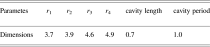
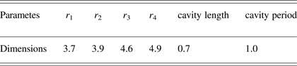
Where J 0 and Y 0 respectively represent ordinary Bessel functions of the first and second kind with order zero. Substituting the main dimensions of the buncher summarized in Table 1 into the Eq. (2) yields the cut-off frequency of the TM02 mode, which is about 25 GHz and far higher than the operation frequency (14.25 GHz).
Main dimensions of trinal-cavity buncher (unit: cm)
One special feature of the coaxial TM01 mode is that by loading the resonant cavities on both of the coaxial inner and outer conductors instead on only one of them and optimizing their depths, the strongest axial electric field can be located in the middle of the cavities, which is defined as quasi body wave. To illustrate the differences of the quasi body wave and the surface one, Figure 2 shows the electric field distribution of the TM01 mode in the cavities loaded on both surfaces of the conductors and only on the outer one. In this paper, we select the quasi body wave as the operation mode. Compared with the traditional device using the surface wave (Zhang et al., Reference Zhang, Zhong and Luo2004) this proposed device has higher power capacity. Moreover, for enhancing the strength of the beam-wave interaction, the electron beam is usually located near the maximum of the electric field. So, for the proposed device, the location of the beams is in the middle of the buncher, which could increase the distance between the IREB and the conductor surface.
(Color online) Electric field distribution for coaxial TM01 mode in (a) cavity only loaded on the outer conductor and (b) cavities loaded on both of the coaxial inner and outer conductors
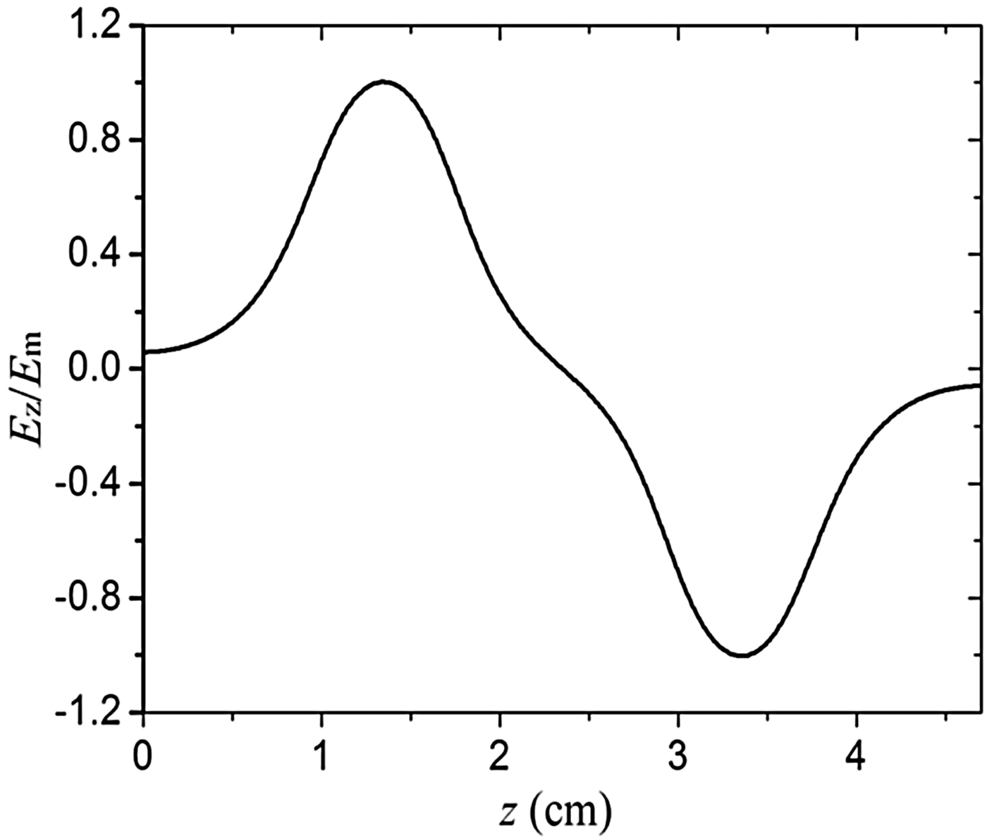
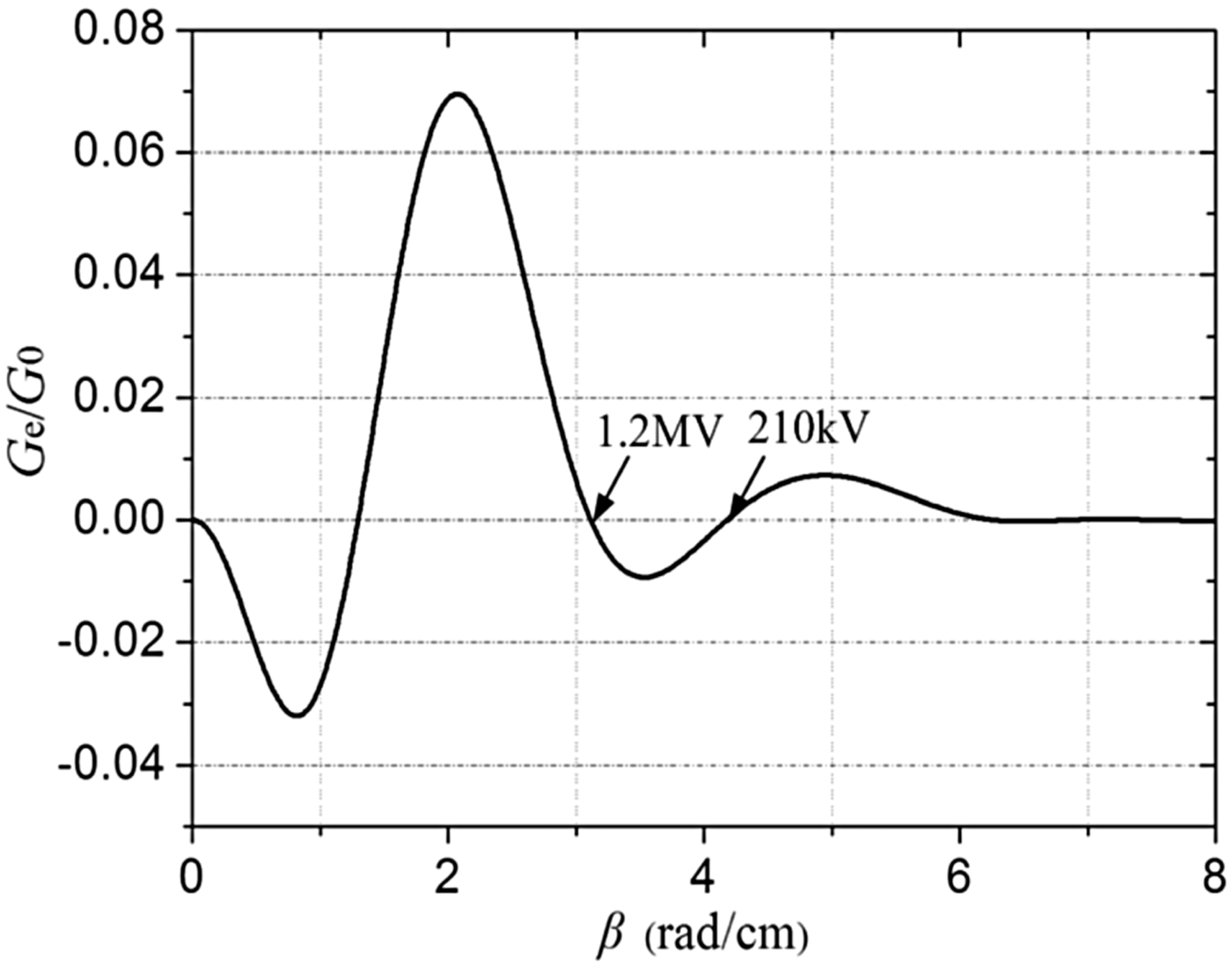
For the TM01 mode in our trinal-cavity buncher, it has three axial modes, which are 0, π/2, quasi-π mode. And the resonant frequencies of them calculated by electromagnetic analyzing software are, respectively, 13.7 GHz, 14.23 GHz, 15 GHz. Based on the small signal theory, for a given structure, the axial mode selection is mainly decided by the operation voltage (Cao et al., Reference Cao, He, Zhang, Zhang and Jin2012b). Combining the distribution function of electric field, we can ascertain the operation voltage range of each mode from the theory. For moderate input voltage (300 kV–500 kV), it can only stimulate the π/2 mode, which has a wide voltage range from 210 kV to 1.2 MV. Figure 3 shows the normalized axial electric field distribution of the π/2 mode of TM01 mode in the trinal-cavity buncher. From the figure, we can see that it have the similar distribution with the quasi-π mode in the dual-cavity which has been successfully used in the L-band TTO. However, in comparison with the dual one (Cao et al, Reference Cao, Zhang and He2009), the dimensions of the trinal-cavity are larger, which would has a much higher power capacity. The calculation results of the operation voltage range for π/2 mode is shown in Figure 4, where G e/G 0 is the normalized conductance of electron. In this figure, negative conductance of electron means losing kinetic energy during transit; contrarily, positive one means getting the energy. And the relationship between the electron phase constant and the working voltage can be expressed as,
Normalized axial electric field distribution of the π/2 mode of TM01 mode in the trinal-cavity buncher.
Normalized conductance of electron versus the electron phase constant.
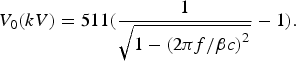 $${V_0}\lpar kV\rpar = 511\lpar \displaystyle{1 \over {\sqrt {1 - {{\lpar {{2{\rm \pi} f} / {{\rm \beta} c}}\rpar }^2}} }} - 1\rpar .$$
Where f is the resonant frequency of the buncher, and β denotes the electron phase constant.
2.3. Design of a Coaxial Reflector
Usually, for making certain the buncher can effectively form the standing wave, the channels of the electron beam located at the two sides of the buncher would cut off the TM01 mode. Nevertheless, the RF field in the buncher could couple into the diode region with the mode of TEM, which will disturb the generation and the transmission of the electron beam. Although decreasing the radial width (△r 1) of the channel could ease the disturbance caused by TEM mode, it would decrease the power capacity and increase the value of the external guiding magnetic field. One effective way for solving above problems is to locate the reflector before the beam-wave interaction region (Teng et al., Reference Teng, Liu, Shao and Tang2009). In our proposed device, we employs a coaxial TM02 mode resonant reflector, compared with the tradition one, the novel reflector has higher capacity. Moreover, the reflector pre-modulates the electron beam before it travels into the interaction region.
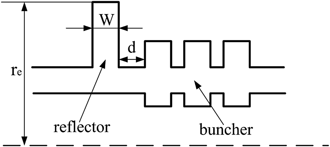
Figure 5 shows a geometry sketch of the reflector with parameters. In order to realize the effective reflection of the TEM mode and pre-modulation of the electron beam, special attentions should be focused mainly on two aspects while designing the reflector. One is to keep a high TEM reflectance at the desired frequency. Another is to ensure the TM02 mode resonant frequency is close enough to the operating frequency that is beneficial for pre-modulating the electron beam. We can select the rough values of the parameters to establish the TM02 mode in the cavity at the desired frequency with the coaxial type cavity design rules. The exact resonant and reflection property can be obtained by the electromagnetic analyzing software with the way of parameter scanning. Based on the theory mentioned above, the parameters can be obtained, w = 5.5 cm, r e = 6.0 cm, d = 0.5 cm, which make the TM02 mode resonant frequency equal to 14.2 GHz and TEM reflectance close to 90% at the frequency range from 14.2 GHz to 14.3 GHz. Figure 6 shows the electrical field distribution in the novel reflector at the desired frequency. As shown in the figure, the position of the maximum electric field closes to the electron transmission line at r = 4.3 cm instead of the corner wall, as is the case in the traditional one (Xiao et al., Reference Xiao, Zhang, Zhang, Li, Zhang, Song, Hu, Sun, Huo, Chen, Zhang and Liu2010), which could increase the power handling capacity and pre-modulation of the electron beam. Moreover, by analyzing the external Q-factor of the buncher, we find that its value increase from 42 to 49, after introducing the novel reflector, which would be more suitable for beam-wave interaction.
Geometry sketch of the reflector.
(Color online) Electric field distribution of the coaxial TM02 mode in the reflector.
2.4. Design of the Low Guiding Magnetic Field
The external guiding magnetic field is very important for the beam propagation in the HPM generator, especially for higher frequency band device with smaller size. Usually, the value of the magnetic field is around or even higher than 2 T. Such strong magnetic field provided by solenoids or even superconducting coils will increase the system's volume, weight, and the consumption of the energy. So it is necessary to reduce the guiding magnetic field to a relatively low value. For our device, the magnetic field is only 0.7 T, which mainly can be attributed to the following three aspects. One is that the radius of annular beam in the coaxial TTO is much larger than that in non-coaxial one, and, therefore, the current density is smaller under the same beam current. Furthermore, adopting the coaxial inner conductor inside the device could significantly reduce the space-charge effects. The deceases of both the current density and the space-charge effects are beneficial for lowering the guiding magnetic field (Zhang et al., Reference Zhang, Zhong and Luo2004).
Another is that by employing a coaxial TM02 mode resonant reflector and quasi body wave as the operating mode, the distance between the electron transmission line and the conductor surface becomes larger. Generally, the transverse velocity of the electron beam could cause it to have a cyclotron motion while it moves along the z-axis. The Larmor cyclotron radius is,
 $${r_L} = \displaystyle{{m{v_ \bot }} \over {qB}}.$$
Where the  ${v_ \bot }$ is horizontal component of the electron velocity. From Eq. (4), we can obtain that smaller magnetic field means larger cyclotron radius; therefore, for this proposed device, by increasing the distance between the beam and conductor surface could effectively decrease the value of the magnetic field.
The third aspect is that during the low magnetic field (less than 1 T), the cyclotron mode of the beam could not be excited. For our device, according to Vlasov et al. (Reference Vlasov, Ilyin and Carmel1998), the magnetic field value related to the cyclotron resonance mode is,
 $$B = \displaystyle{{2v_z } \over {{e / m}}}{\rm \gamma} _0 \displaystyle{{\rm \pi} \over {L_0 }}.$$
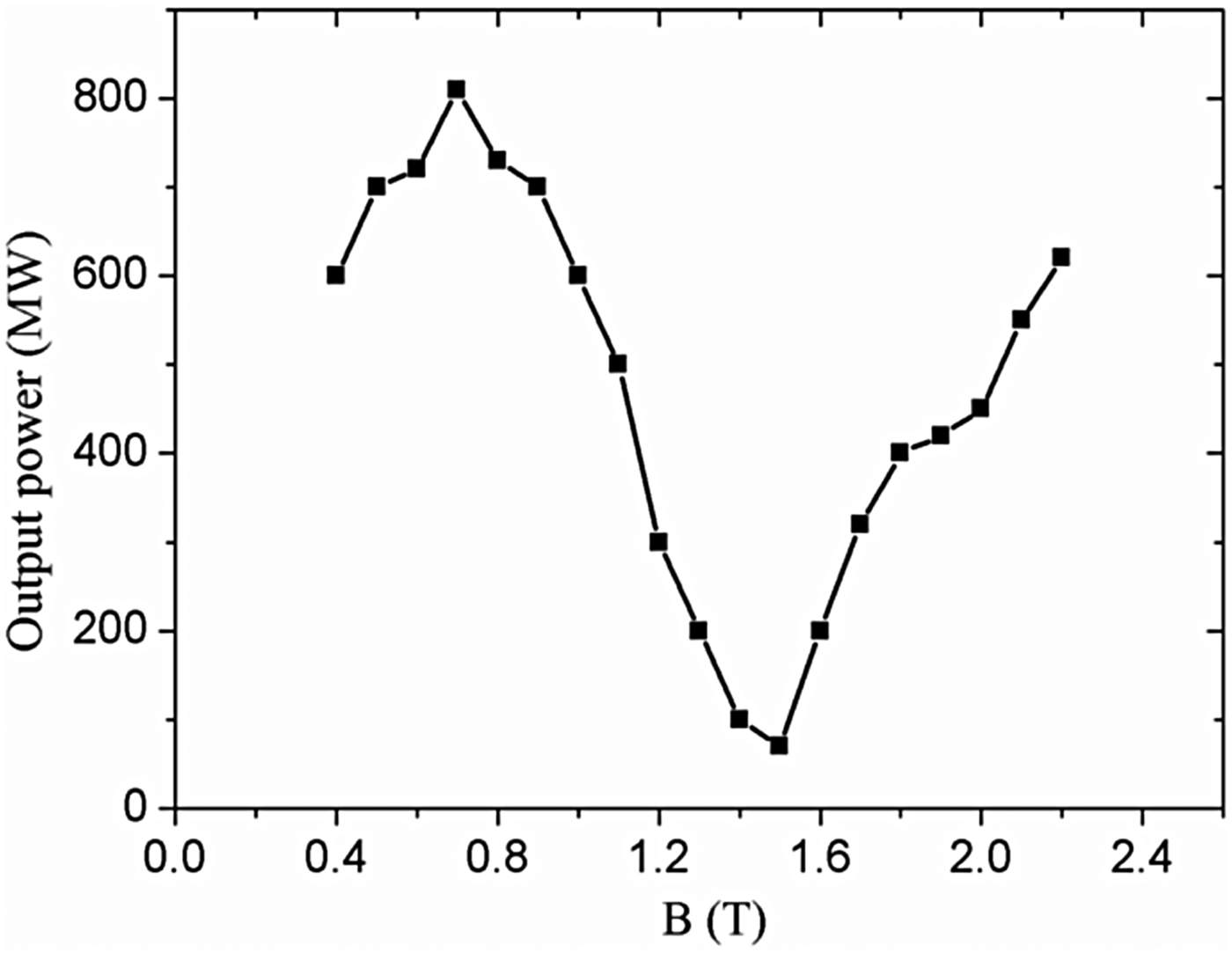
Where e, m, γ0, v z are the charge, mass, relativistic factor, and the longitudinal velocity of the electron, respectively; L 0 is the period of the buncher. Substituting the main parameters in Table 1 into the Eq. (5), we can get B = 1.46 T when diode voltage is equal to 358 kV. So we can choose a relatively low magnetic field away from this value. Figure 7 gives the relation between the output microwave power and magnetic field calculated by PIC simulation. From the figure, we can find that in the region of 0.7 T, the device can output the highest power (810 MW), and even with a lower magnetic field (0.4 T), the output power can reach above 500 MW; such results have proved the feasibility of the device operation with low guiding magnetic field. It can be also seen from the figure that there is an obvious power dip in the region of 1.5 T, which corresponds to the cyclotron resonance mode B calculated in Eq. (5).
Output microwave power versus guiding magnetic field.
3. SIMULATION RESULTS
In order to investigate the proposed Ku-band TTO with low guiding magnetic field and validate its performance, we carry out a two-and-one-half-dimensional (2.5D) PIC simulations on the proposed device by the CHIPIC code (User's Manual of Code CHIPIC, 2004; Zhou et al., Reference Zhou, Liu, Liao and Li2009), when the diode voltage is about 358 kV, the diode current is about 7.25 kA, and the guiding magnetic field is about 2 T. The structure has already been described in Figure 1. The main simulation results are shown as follows.
Figure 8 displays the typical phase space plot of the proposed device at the moment of 35 ns. It indicates that a weak modulation occurs after the electron beam passed through the coaxial TM02 mode resonant reflector, and a further modulation appears in the buncher. The energy spread of the modulated beam electrons decreases greatly after a given-distance drift. In the region of the extractor, the beam-wave interaction is very intensive, and most electrons lose their energy, that means the beam energy is converted into the microwave energy effectively.
(Color online) Typical phase space plot of the proposed device at the moment of 35 ns
To illustrate functions of the coaxial TM02 mode resonant reflector, which is one of the key parts in our proposed device, we conduct a comparative investigation on the device with the reflector and without it. The PIC code can directly monitor the leakage power from buncher to the diode region by calculating the integral of the Poynting flux over the cross-section loaded before the position of the reflector. As shown in Figure 9, the leakage power of the device without the reflector is about 140 MW, but for the proposed one with the coaxial TM02 mode resonant reflector, the leakage power is 42 MW, that proves this reflector can effectively prevent the microwave from propagating to diode. Figure 10 gives the beam modulation spectrum by the reflector. According to this figure, in the total beam current which travels through the reflector and dose not enter the buncher, the ratio of the modulated component to the dc component is 11.4%. Compared with the one without reflector, the pre-modulation of the electron beam will be beneficial for the subsequent beam-wave interaction.
(Color online) Leakage power of the device with the coaxial TM02 mode resonant reflector and without it.
(Color online) Beam modulation spectrum by the coaxial TM02 mode reflector.
Figure 11 shows the output microwave power versus time. Here, the result obtained with the proposed TTO with the coaxial TM02 mode resonant reflector is compared with that obtained without it. For the two cases, with the diode voltage of 358 kV, diode current of 7.25 kA and the guiding magnetic field of 0.7, the output power are 810 MW and 680 MW, giving the beam-to-microwave conversion efficiencies of 31% and 26%, respectively, and the microwave frequencies are both 14.25 GHz. Figure 12 is the frequency spectrum of the output microwave in the proposed device, which shows that the spectrum is clean and the dominant frequency is close to the cold resonant frequency 14.23 GHz mentioned in Section 2, which indicates the operating mode is π/2 mode of the TM01 mode.
(Color online) Plot of the output power versus time.
(Color online) Output power frequency spectrum.
4. EXPERIMENTAL SETUP AND RESULTS
4.1. Experimental Setup
The proposed Ku-band TTO with the designed parameters derived above was fabricated. For investigating and verifying its performance, a primary experiment on this Ku-band device guided by the magnetic field was performed at the TORCH-01 IREB accelerator, which is capable of producing a 50 ns duration electron beam in the voltage range of 0.3–1 MV. Figure 13 illustrates the photograph of the experiment setup, including the IREB accelerator and the proposed Ku-band device with the solenoid coils. In the experiments, the guiding magnetic field and its profile were measured by a Tesla-meter based on the Hall-effect. The diode voltage and the beam current were measured by a capacitive voltage divider and a Rogovsky coil, respectively. The generated microwave was received simultaneously by two horns, which were actually the BJ140 type open-ended waveguide, located in the far-field zones. One of the received microwave signals was detected by a calibrated RF detector via the attenuators. The microwave power was calculated based on the integral of power density in the radiation field. Another received signal was used for directly measuring the microwave frequency by using an Aglient-92504A oscilloscope.
(Color online) Photograph of the experiment setup.
4.2. Measurement Results
Figure 14 shows the signal from the Aglient-92504A oscilloscope with sampling rates of 80 Gs/s employed to measure the frequency of the proposed device by performing Fast Fourier Transform (FFT) on the received time-dependent waveform. The measured radiation frequency was 14.3 GHz with a very narrow band. The result was in good agreement with the simulation result.
(Color online) Microwave signal and its frequency spectrum
In the dual-cavity extractor, HPM generated by the modulated IREB is coupled into the coaxial waveguide in the form of TEM mode. The TEM mode is transformed into TM01 mode in a hollow waveguide by a mode converter before it is radiated into the outer space. Figure 15 shows the measured microwave radiation pattern that is well in good agreement with the theoretical pattern of the symmetric TM01 mode, which indicates the generator operating with the single mode (coaxial TM01 mode).
(Color online) The radiation pattern at the far-field
Figure 16 gives the typical waveforms of the diode voltage, the beam current and the radiated microwave. The diode voltage and beam current were respectively 360 kV and 7.2 kA, and the guiding magnetic field was 0.7 T. The diagram shows that the microwave output power was about 400 MW at an efficiency of 15.4% and the corresponding microwave pulse duration corresponding pulse is about 30 ns. The experimental results agree with the simulation results except that the experimental microwave power is obviously lower. The reasons could be that: (1) The diode voltage and the beam current fluctuates obviously, which is probably caused by the impedance mismatch between the proposed device (about 50 Ω) and the IREB accelerator (about 100 Ω), but in simulation they are set to be rectangular waves; (2) In the experiments, due to the error in the process of the fabrication, we find that the match between the inner and outer conductors is not well, which will cause the annual electron beam, inner and outer conductors non-coaxial; (3) After the experiments, there is a obvious imprint of the IREB on the collector, which illustrates high energy and high density of the electron beam, and such a beam might cause the secondary electron emission with the plasma, which will change the boundary conditions of the extractor and be unprofitable for the generation of microwaves. Next, we will try to solve above problems for further improving the output power, such as carrying out the experiments on the IREB accelerator with the same impedance, making sure the electron beam, inner and outer conductors coaxial, settling the electron collector away from the RF extractor and making the beam interception occur over an inclined plane, which has a larger dump area compared with a vertical plane.
(Color online) Typical waveforms of power measurement. CH1 is the diode voltage, CH2 is the beam current, and CH3 corresponds to the microwave envelope from the receiving horn.
5. CONCLUSIONS
A novel Ku-band coaxial relativistic transit-time oscillator with low guiding magnetic field is proposed and investigated in this paper. With the coaxial structure and a quasi body wave adopted as the operating mode, the device has a larger space-charge limiting current, higher power handling capacity and lower guiding magnetic field. By use of a well-designed coaxial TM02 mode resonant cavity before the buncher, it can not only prevent the TEM mode from propagating to the diode region and pre-modulate the electron beam passing through it, but also further lower the operation magnetic filed and improve the power handling capacity. PIC simulations show that, with a 358 keV, 7.25 kA beam guided by a magnetic field of about 0.7 T, the device can generate an 810 MW microwave pulse at 14.25 GHz, yielding a conversion efficiency of about 31%.
A primary experiment was carried out on the TORCH-01 accelerator to verify the design of our proposed device. At a diode voltage of 360 kV, beam current of 7.2 kA, and a guiding magnetic field of 0.7 T, a microwave pulse with power of 400MW, pulse duration of 30 ns, frequency of 14.3 GHz, and efficiency of 15.4% was output. It was demonstrated that a single-mode, narrow-band HPM in Ku-band can be generated effectively with the novel coaxial TTO. The experimental results are in good agreement with the results of the simulation, except the output power. In future, we will make efforts on perfecting the match between the inner and outer conductors, improving the effect of the electron beam and carrying out the experiments on the IREB accelerator with the impedance close to the proposed device for outputting higher power in Ku-band.
ACKNOWLEDGMENTS
This work was supported by the National Natural Science Foundation of China under Grant No. 61171021. The authors wish to thank Dr. Yi-Bing Cao for helpful discussions. The authors also thank the editor and the referee for their help and suggestions.