Nomenclature
-
 $\{I\}$
-
Inertial frame of reference with three orthogonal unit vectors {
${e_{\bf{1}}},{e_{\bf{2}}},{e_{\bf{3}}}$
} -
$\{B\}$
-
Body frame of reference of the quadcopter with three orthogonal unit vectors {
${b_{\bf{1}}},{b_{\bf{2}}},{b_{\bf{3}}}$
} -
$g\in\mathbb{R}$
-
Acceleration due to gravity
-
$m\in \mathbb{R}$
-
Mass of the quadcopter
-
$\boldsymbol{J} \in \mathbb{R}^{3 \times 3}$
-
Moment of inertia of the quadcopter in frame
$\{B\}$
-
$\phi, \theta, \psi$
-
Roll, pitch, and yaw angles of the quadcopter
-
$\boldsymbol{R}\in SO(3)$
-
Attitude of the quadcopter
-
$\boldsymbol{\omega} \in \mathbb{R}^{3}$
-
Body frame angular velocity of the quadcopter
-
$m_p\in \mathbb{R}$
-
Mass of the payload
-
$l \in \mathbb{R}$
-
Length of the cable
-
$\phi_p, \theta_p$
-
Cable attitude about
$\boldsymbol{e}_{\boldsymbol{1}}$
and
$\boldsymbol{e}_{\boldsymbol{2}}$
axes -
$\phi_{p_{,CAM}}, \theta_{p_{,CAM}}$
-
Cable attitude measured by CAM device about
$\boldsymbol{b}_{\boldsymbol{1}}$
and
$\boldsymbol{b}_{\boldsymbol{2}}$
axes -
$\phi_c, \theta_c$
-
Cable Attitude Controller commands along roll and pitch angle
-
$(\phi_h, \theta_h, \dot{\psi}_h, \dot{z}_h)$
-
Higher level command for roll angle, pitch angle, desired yaw rate, and desired velocity along
$\boldsymbol{e}_{\boldsymbol{3}}$
axis of the quadcopter -
$\boldsymbol{X} = [x,\,y,\,z]^{T} \in \mathbb{R}^{3}$
-
Position of the quadcopter in the inertial frame
-
$\boldsymbol{X}_{\boldsymbol{p}} = [x_p,\,y_p,\,z_p]^{T} \in \mathbb{R}^{3}$
-
Position of the payload in the inertial frame
-
$F\in \mathbb{R}$
-
Total thrust generated by the quadcopter
-
$\boldsymbol{M} = [M_{1},M_{2},M_{3}]^{T} \in \mathbb{R}^{3}$
-
Moment generated by the quadcopter about the
$\boldsymbol{b}_{\boldsymbol{1}}, \boldsymbol{b}_{\boldsymbol{2}}$
and
$\boldsymbol{b}_{\boldsymbol{3}}$
axes


1. Introduction
Many field applications, such as automotive and packaging industries, agriculture and warehouse applications, and construction sites, involve repetitive transportation of materials/objects from one place to another. Deploying robotics devices to perform these repetitive activities can be cost effective and enhance overall productivity by reducing material handling time. Various kinds of robotic devices have been used to perform specific types of applications [Reference Cubero1], the majority of which are programmed to execute the tasks autonomously and often in well-structured environments. The reachable workspace is an important aspect of such robotic applications. Notably, aerial robots can be deployed in dynamic and unstructured outdoor environments with a relatively larger workspace, and their use for the task of transportation has been proposed for applications in payload delivery [Reference Kim and Matson2]. Extending quadcopters for impromptu payload transportation in outdoor settings can help reduce infrastructure costs and improve productivity.
In the literature, various methodologies have been proposed for aerial transportation using quadcopters. The payloads are mainly transported by being directly attached to the quadcopter’s chassis [Reference Thomas, Loianno, Polin, Sreenath and Kumar3, Reference Mellinger, Lindsey, Shomin and Kumar4, Reference Mellinger, Shomin, Michael and Kumar5, Reference Loianno and Kumar6, Reference Wang, Singh, Pavone and Schwager7] or grabbed using the mechanical arms/grippers [Reference Kim, Choi and Kim8, Reference Pereira, Zanella and Dimarogonas9] or suspended using the cables. The authors in ref. [Reference Lindsey, Mellinger and Kumar10] presented a case where quadcopters autonomously pick and place rectangle-shaped modular elements to create special cubic structures, and the authors in ref. [Reference Augugliaro, Lupashin, Hamer, Male, Hehn, Mueller, Willmann, Gramazio, Kohler and D’Andrea11] demonstrated cooperative construction of 7 m height architecture using rectangle foam elements. The authors in the refs. [Reference Augugliaro, Mirjan, Gramazio, Kohler and D’Andrea12, Reference Mirjan, Gramazio, Kohler, Augugliaro and D’Andrea13] also presented a case where quadcopters cooperatively constructed a tensile structure using ropes to create a temporary bridge. The use of mechanical arms/grippers or direct attachment of payloads affects the flight dynamics of the quadcopter and gets limited by payloads’ size and shape. In contrast, transporting a payload through a cable attached at the quadcopter’s center of mass (COM) can be advantageous as the quadcopter’s attitude dynamics remain unaffected, which provides agility. Further, cable suspension can be easily extended for cooperative payload transportation. However, cable suspended payloads are prone to oscillations during transportation, which requires control strategies to eliminate oscillations.
Various methods have been presented in the literature for a quadcopter with a cable-suspended payload system to track complex trajectories with minimal payload oscillations, such as differential flatness-based controllers [Reference Sreenath, Lee and Kumar14, Reference Sreenath, Michael and Kumar15, Reference Kotaru, Wu and Sreenath16, Reference Zeng, Kotaru, Mueller and Sreenath17, Reference Zeng, Kotaru and Sreenath18], optimal controllers [Reference Tang and Kumar19, Reference Foehn, Falanga, Kuppuswamy, Tedrake and Scaramuzza20, Reference De La Torre, Theodorou and Johnson21, Reference Dai, Lee and Bernstein22, Reference Guo and Leang23, Reference Guerrero-Sánchez, Mercado-Ravell, Lozano and García-Beltrán24], and reinforcement learning-based controllers [Reference Faust, Palunko, Cruz, Fierro and Tapia25, Reference Faust, Palunko, Cruz, Fierro and Tapia26]. In addition, the use of multiple aerial robots to lift a payload cooperatively can increase the load-carrying capacity and has been the focus of many studies. The authors in refs. [Reference Lee, Sreenath and Kumar27, Reference Goodarzi and Lee28, Reference Mohammadi, Sirouspour and Grivani29] demonstrated such a modality in an indoor environment where required feedback of the states was estimated using a motion capture system. Using image processing techniques in refs. [Reference Gassner, Cieslewski and Scaramuzza30, Reference Bisgaard31, Reference Tang, Wüest and Kumar32] and rotary encoders in refs. [Reference Bernard and Kondak33], the authors demonstrated estimation of the cable attitude to stabilize the payload swings during autonomous outdoor transportation. The authors in refs. [Reference Tagliabue, Kamel, Verling, Siegwart and Nieto34, Reference Tagliabue, Kamel, Siegwart and Nieto35] demonstrated collaborative transportation using multiple quadcopters by utilizing force and admittance controller.
Considering the underactuated, nonlinear, and coupled dynamics of a quadcopter with cable-suspended payload system, the existing works [Reference Sreenath, Lee and Kumar14, Reference Sreenath, Michael and Kumar15, Reference Kotaru, Wu and Sreenath16, Reference Zeng, Kotaru, Mueller and Sreenath17, Reference Zeng, Kotaru and Sreenath18, Reference Tang and Kumar19, Reference Foehn, Falanga, Kuppuswamy, Tedrake and Scaramuzza20, Reference De La Torre, Theodorou and Johnson21, Reference Dai, Lee and Bernstein22, Reference Guo and Leang23, Reference Guerrero-Sánchez, Mercado-Ravell, Lozano and García-Beltrán24, Reference Faust, Palunko, Cruz, Fierro and Tapia25, Reference Faust, Palunko, Cruz, Fierro and Tapia26, Reference Tang, Wüest and Kumar32] have been focused on the development of agile, autonomous, and accurate trajectory tracking to perform specific tasks. Accordingly, for localization in indoor settings motion capture system is widely used; however, it restricts outdoor applications. For localization and obstacle avoidance in unstructured outdoor environments, external sensors such as LIDARS, cameras, and visual-inertial odometry, become necessary to install. Also, enabling fully autonomous flight in variable and changing outdoor environments is a computationally costly and challenging task. Alternatively, some of the human-in-the-loop modalities presented in refs. [Reference Lee, Franchi, Son, Ha, Bülthoff and Giordano36, Reference Masone, Bülthoff and Stegagno37, Reference Prajapati, Parekh and Vashista38, Reference Prajapati, Parekh and Vashista39, Reference Vergouw, Nagel, Bondt and Custers40, Reference Perez-Grau, Ragel, Caballero, Viguria and Ollero41] have demonstrated the involvement of human operators in various capacities to show potential benefits in high-level logical planning and established successful teleoperation of a complex and coupled dynamical system.
The current work present a preliminary design and control approach that enables stable and smooth human-controlled aerial transportation of cable-suspended payload using a quadcopter in outdoor environment. The main components of this approach include on-board integration of a portable sensor device to accurately measure the cable states and a controller to minimize the payload oscillations using the cable state feedback during outdoor flight. The current work further demonstrates the feasibility of this approach through two outdoor flight modalities, namely (1) semi-autonomous flight and (2) Human-controlled flight. Finally, a preliminary case study is presented to demonstrate the feasibility of the proposed modality in outdoor applications such as impromptu aerial transportation at a construction site.
2. Methods
2.1. Dynamical model
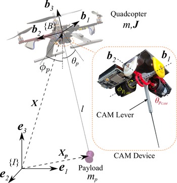
The quadcopter with a cable-suspended payload system is shown in Fig. 1. The inertial reference frame and body-fixed reference frame of the quadcopter are denoted as three orthogonal unit vectors {
 $\boldsymbol{e}_{\boldsymbol{1}}, \boldsymbol{e}_{\boldsymbol{2}}, \boldsymbol{e}_{\boldsymbol{3}}$
} and {
 $\boldsymbol{b}_{\boldsymbol{1}}, \boldsymbol{b}_{\boldsymbol{2}}, \boldsymbol{b}_{\boldsymbol{3}}$
}, respectively. The third inertial frame axis,
 $\boldsymbol{e}_{\boldsymbol{3}}$
, is taken as the vertically upward direction and the third body-fixed axis of the quadcopter,
 $\boldsymbol{b}_{\boldsymbol{3}}$
, is taken perpendicular to the plane of the quadcopter, pointing upwards. The position of the quadcopter and the payload in frame
 $\{I\}$
are denoted by
 $\boldsymbol{X} = [x, \,\,y, \,\,z]^{T} \in \mathbb{R} ^{3}$
and
 $\boldsymbol{X}_{\boldsymbol{p}} = [x_p, \,\,y_p, \,\,z_p]^{T} \in \mathbb{R} ^{3}$
, respectively. The attitude of the quadcopter is represented by standard ZXY Euler angle representation, rotation matrix
 $\boldsymbol{R} \in SO(3)$
, such that, (
 $\phi,\,\, \theta, \,\,\psi$
) define the quadcopter’s roll, pitch, and yaw angle, respectively, [Reference Michael, Mellinger, Lindsey and Kumar42]. The angular velocity of the quadcopter in frame
 $\{B\}$
is denoted as
 $\boldsymbol{\omega} \in \mathbb{R}^{3}$
. The attitude of the cable is represented as the angular position of the cable along
 $\boldsymbol{e}_{\boldsymbol{1}}$
and
 $\boldsymbol{e}_{\boldsymbol{2}}$
axes, that is,
 $\phi_p$
and
 $\theta_p$
, respectively.
 $m \in \mathbb{R}$
and
 $\boldsymbol{J} \in \mathbb{R}^{3\times3}$
denote quadcopter’s mass and moment of inertia in frame
 $\{B\}$
.
 $m_p \in \mathbb{R}$
and
 $l \in \mathbb{R}$
denote payload’s mass and cable length, respectively. The cable is considered to be massless and when it remains taut, the position of the payload in frame
 $\{I\}$
is given by Eqs. (1 and 2), where
 $c({\cdot})= cos({\cdot}) $
and
 $s({\cdot}) = sin ({\cdot})$
.
 \begin{equation} \boldsymbol{X}_{\boldsymbol{p}} = \boldsymbol{X} + {\boldsymbol{R}_{\boldsymbol{x}}(\boldsymbol\phi_{\boldsymbol{p}})}\,\, {\boldsymbol{R}_{\boldsymbol{y}}(\boldsymbol\theta_{\boldsymbol{p}})} \begin{bmatrix} 0 & 0 & -l \end{bmatrix}^T \end{equation}
 \begin{equation} {\boldsymbol{R}_{\boldsymbol{x}}(\boldsymbol\phi_{\boldsymbol{p}})} = \begin{bmatrix} 1 & \quad 0 & \quad 0 \\[3pt] 0 & \quad c\phi_{p} & \quad -s\phi_{p}\\[3pt] 0 & \quad s\phi_{p} & \quad c\phi_{p} \end{bmatrix}, \,\,\,\,\, {\boldsymbol{R}_{\boldsymbol{y}}(\boldsymbol\theta_{\boldsymbol{p}})} = \begin{bmatrix} c\theta_{p}& \quad 0&\quad s\theta_{p} \\[3pt] 0 & \quad 1& \quad 0 \\[3pt] -s\theta_{p}& \quad 0 & \quad c\theta_{p} \end{bmatrix} \end{equation}
Experimental setup of a quadcopter and a cable-suspended payload system. The payload is suspended using a cable through the CAM device, which is mounted underneath quadcopter’s chassis.
 $\boldsymbol{X}$
and
 $\boldsymbol{X}_{\boldsymbol{p}}$
denote the position vectors of the quadcopter and payload in the inertial frame,
 $\{I\}$
, respectively.
 $\phi_p$
and
 $\theta_p$
are the angular position of the cable about
 $\boldsymbol{e}_{\boldsymbol{1}}$
and
 $\boldsymbol{e}_{\boldsymbol{2}}$
axes, respectively.
 $\{B\}$
is the body-fixed reference frame attached to quadcopter’s principal axis.
 $\phi_{p_{,CAM}}$
and
 $\theta_{p_{,CAM}}$
are the cable attitude measured by CAM device about
 $\boldsymbol{b}_{\boldsymbol{1}}$
and
 $\boldsymbol{b}_{\boldsymbol{2}}$
axes respectively

The total thrust force and moment generated by four motors of the quadcopter are denoted as
 $F \in \mathbb{R}$
and
 $\boldsymbol{M} =[ M_1, \,\, M_2, \,\, M_3]^{T}\in \mathbb{R}^{3}$
, respectively. Using Euler–Lagrange’s equation, the equations of motion for the quadcopter-payload system with cable attachment at the quadcopter’s center are given in Eqs. (3 and 4). A vector,
 $\boldsymbol{s}$
, is used to define quadcopter’s position and cable attitude,
 $\boldsymbol{s} = [\boldsymbol{X}^T, \,\, \phi_p, \,\, \theta_p]^{T}$
. The matrices
 $\boldsymbol{\mathcal{M}} ({\boldsymbol{s}}) \in \mathbb{R}^{5 \times 5}$
,
 ${\boldsymbol{C}(\boldsymbol{\textit{s,}}\dot{\boldsymbol{s}})} \in \mathbb{R}^{5 \times 5}$
, and
 ${\boldsymbol{G}(\boldsymbol{s})}\in\mathbb{R}^{5 \times 1}$
are inertia, coriolis & centrifugal, and gravity terms and their expression are given in the Appendix.
 \begin{eqnarray}{\boldsymbol{\mathcal{M}}(\boldsymbol{s})} {\ddot{\boldsymbol{s}}} + {\boldsymbol{C} (\boldsymbol{\textit{s,}}\dot{\boldsymbol{s}})} {\dot{\boldsymbol{s}}} + {\boldsymbol{G}(\boldsymbol{s})} &=& \begin{bmatrix} F \boldsymbol{R} \boldsymbol{e}_{\boldsymbol{3}} \\[3pt] 0_{2 \times 1}\end{bmatrix} \end{eqnarray}
 \begin{eqnarray}\boldsymbol{J} {\dot{\boldsymbol\omega}} + \boldsymbol{\omega} \times J \boldsymbol{\omega} &=& \boldsymbol{M} \end{eqnarray}
2.2. CAM device
In the current work, a custom built sensor setup, referred to as cable attitude measurement (CAM) device, is mounted under the quadcopter’s chassis to suspend the payload. Similar to a joystick functioning, CAM device allows and measures the rotation of its lever about two orthogonal axes,
 $\boldsymbol{b}_{\boldsymbol{1}}$
and
 $\boldsymbol{b}_{\boldsymbol{2}}$
, as shown in Fig. 1. Similar approaches have been used in prior works to estimate cable attitude in a cable driven parallel robot [Reference Fortin-Côté, Cardou and Campeau-Lecours43] and for transporting suspended payload using helicopter [Reference Bernard and Kondak33]. The current work achieves a portable design with sensing and communication capabilities for a quadcopter to measure cable attitude. Consequently, enabling the implementation of an on-board controller that minimizes payload oscillations for outdoor flights. In brief, CAM device uses two 12-bit magnetic encoders from Broadcom Inc. that are aligned with
 $\boldsymbol{b}_{\boldsymbol{1}}$
and
 $\boldsymbol{b}_{\boldsymbol{2}}$
axes. To extract the readable data from the encoders, NodeMCU ESP8266 WiFi module is used. The device has a 3D printed base made of polylactic acid plastic with a size of
 $6 \, \textrm{cm} \times 6 \, \textrm{cm} \times 3 \, \textrm{cm}$
. The mass of the device is
 $80\,\, \textrm{g}$
and can measure angles in the range
 $[-65^\circ \,\,\, 65^\circ]$
about the two axes. The cable is attached to an extended rod, labeled as CAM lever, which passes through the slotted
 $\boldsymbol{b}_{\boldsymbol{2}}$
axis to be attached to
 $\boldsymbol{b}_{\boldsymbol{1}}$
axis, as shown in Fig. 1. Accordingly, CAM device measures cable attitude in frame
 $\{B\}$
, that is,
 $\phi_{p_{,CAM}}$
and
 $\theta_{p_{,CAM}}$
about
 $\boldsymbol{b}_{\boldsymbol{1}}$
and
 $\boldsymbol{b}_{\boldsymbol{2}}$
axes, respectively, at a rate of 760 Hz.
In this work, a custom-made PX4 autopilot-based quadcopter with an X-configuration frame and arm lengths of
 $23\, \textrm{cm}$
is used. Consumer grade motors, electronic speed controllers (ESCs), and propellers are used that allowed a maximum thrust-to-weight ratio of
 $3:1$
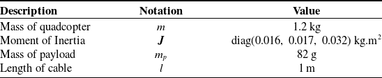
. The physical parameters of the experimental platform are mentioned in Table I. The CAM device is rigidly mounted below the quadcopter’s chassis, such that the chassis geometrical center and CAM lever pivot point are aligned in the chassis plane and have a small offset of
 $2\, \textrm{cm}$
along
 $\boldsymbol{b}_{\boldsymbol{3}}$
axis.
Physical parameters of the experimental setup

With the cable attitude values in frame
 $\{B\}$
,
 $\phi_{p_{,CAM}}$
, and
 $\theta_{p_{,CAM}}$
, the payload position in frame
 $\{I\}$
is written in Eq. (5), where quadcopter’s attitude,
 $\boldsymbol{R}$
, from an on-board IMU is utilized. For simplicity, the effect of offset along
 $\boldsymbol{b}_{\boldsymbol{3}}$
axis is ignored. Accordingly, cable attitude in frame
 $\{I\}$
, that is,
 $\phi_p$
and
 $\theta_p$
, are evaluated by equating Eqs. (1 and 5).
 \begin{equation} \boldsymbol{X}_{\boldsymbol{p}} = \boldsymbol{X} + \boldsymbol{R} \,\, {\boldsymbol{R}_{\boldsymbol{x}}(\boldsymbol\phi_{\boldsymbol{p}_{\boldsymbol{\textit{,CAM}}}})} \,\, {\boldsymbol{R}_{\boldsymbol{y}}(\boldsymbol\theta_{\boldsymbol{p}_{\boldsymbol{\textit{,CAM}}}})} \,\, \begin{bmatrix} 0 & 0 & -l \end{bmatrix}^{T} \end{equation}
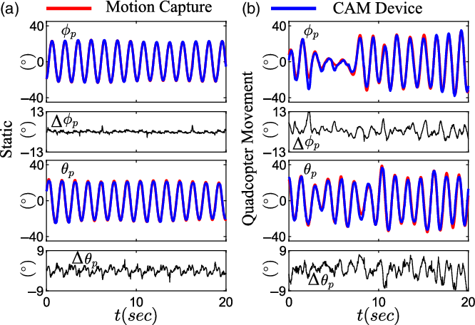
Validation: Cable attitude measurements from the CAM device are verified using a motion capture system from Vicon. In Fig. 2, two sets of experimental data are presented, (A) static trial, where the suspended payload was perturbed with the system rigidly mounted on a stationary frame and (B) quadcopter movement trial, where the quadcopter’s chassis was moved manually in the workspace to induce payload oscillations.
The experimental results of the CAM device validation. (A) Static trial: where the suspended payload was perturbed with the system rigidly mounted on a stationary frame. (B) Quadcopter movement trial: where the quadcopter’s chassis was moved manually in the workspace to induce payload oscillations.
 $\Delta \phi_p$
and
 $\Delta \theta_p$
are the difference between motion capture data to CAM device data

A close match is observed between the cable attitude values, represented in frame
 $\{I\}$
, between the two data sources for both the trials. Small differences
 $(\Delta\phi_p, \Delta \theta_p)$
are also observed particularly at payload’s extreme positions, which can be due to the cumulative effect of swinging payload inertia and CAM device friction. Relatively small root mean square error in (
 $\phi_p$
,
 $\theta_p$
) values are observed (
 $1.5^\circ$
,
 $1.8^\circ$
) for trial (A) and (
 $3.16^\circ$
,
 $3.12^\circ$
) for trial (B). With these relatively small errors, CAM device provides a reasonable feedback of the cable attitude in real-time that is used for CAC to minimize the payload oscillations during the flight.
2.3. On-board controller design
The overall objective of the controller is to enable stable and smoother outdoor aerial transportation of a cable-suspended payload using a quadcopter. In this context, an on-board control strategy that establishes a threefold interaction between a human operator, CAM device, and PX4 autopilot controller is implemented. In particular, the controller is designed to take higher level commands in the form of quadcopter’s roll,
 $\phi_h$
, pitch,
 $\theta_h$
, yaw rate,
 $\dot{\psi}_h$
, and velocity along
 $\boldsymbol{e}_{\boldsymbol{3}}$
axis,
 $\dot{z}_h$
, to attain a specific quadcopter attitude and altitude respectively. These values over time decide the desired quadcopter’s path to be followed, say
 $\boldsymbol{X}_{\boldsymbol{d}} = [x_d, \,y_d, \,z_d]^{T}$
. Furthermore, based on the cable attitude feedback from the CAM device, the controller administers countermeasures to minimize payload oscillations during payload transportation while executing the commanded maneuver
 $\boldsymbol{X}_{\boldsymbol{d}}$
. Accordingly, the total thrust force and moment, F and
 $\boldsymbol{M}$
, are generated to fly the quadcopter-payload system.
To formulate the control architecture, a linearized model of the system in Eqs. (3 and 4) is developed about the hover equilibrium configuration, marked by zero quadcopter’s translational position and velocity, (
 $\boldsymbol{X} = {\dot{\boldsymbol{X}}} = [0\,,0\,,0]^{T}$
), zero quadcopter’s roll-pitch-yaw angles, (
 $\phi = \theta = \psi = 0$
), zero quadcopter’s angular rates, (
 $\dot{\phi} = \, \dot{\theta} = \, \dot{\psi} = 0$
), and zero cable attitude and its rates, (
 $\phi_p =\, \theta_p= 0, \, \dot{\phi}_p= \, \dot{\theta}_p = 0$
). Further, the thrust force and moment generated by the quadcopter at the hover equilibrium configuration are
 $F = (m+m_p)g$
and
 $\boldsymbol{M} = [0\,,0\,,0]^{T}$
, respectively. The linearized model is represented in Eqs. (6-8), where,
 $m_t = (m + m_p)$
. Noting that the quadcopter’s attitude dynamics, Eq. (7), is not affected by its translational dynamics, Eq. (6), and payload’s rotational dynamics, Eq. (8). Hence, quadcopter’s attitude controller can be designed separately. In this work, we utilized PX4 autopilot’s attitude controller that generates required moment
 $\boldsymbol{M}$
to track the desired attitude of the quadcopter, that is (
 $\phi_d,\,\,\theta_d,\,\,\psi_d$
). This attitude controller is based on the standard PID controller, as described in [Reference Meier, Tanskanen, Fraundorfer and Pollefeys44, 45].
 \begin{eqnarray} \ddot{x} = \frac{m_t g }{m}\theta - \frac{m_p g}{m} \theta_p, \,\,\, \ddot{y} = -\frac{m_t g }{m}\phi + \frac{m_p g}{m} \phi_p, \,\,\, \ddot{z} = \frac{F}{m_t} - g \end{eqnarray}
 \begin{equation} \ddot{\phi} = \frac{M_1}{J_1}, \quad \ddot{\theta} = \frac{M_2}{J_2} , \quad \ddot{\psi} = \frac{M_3}{J_3} \end{equation}
 \begin{equation} \ddot{\phi}_p = \frac{m_t g}{m l} \phi - \frac{m_t g}{m l} \phi_p, \quad \ddot{\theta}_p = \frac{m_t g}{m l} \theta - \frac{m_t g}{m l} \theta_p \end{equation}
From the linearized system’s dynamics, Eqs. (6–8), it is noted that the quadcopter’s attitude dynamics in
 $\phi$
and
 $\theta$
can regulate the quadcopter’s translational dynamics, specifically along
 $\boldsymbol{e}_{\boldsymbol{1}}$
and
 $\boldsymbol{e}_{\boldsymbol{2}}$
axes, and also the payload’s rotational dynamics, which are also coupled with each other. Accordingly, the values of angles (
 $\phi_d,\,\theta_d$
) in the attitude controller are planned to navigate the system along desired course with reduced payload oscillations. In particular, from the coupled terms of Eqs. (6) and (8), quadcopter’s roll and pitch (
 $\phi$
,
 $\theta$
) are extracted as in Eq. (9). Error dynamics in quadcopter’s position and payload attitude is defined in Eq. (10), where
 $e_{({\cdot})} = ({\cdot}) - ({\cdot})_d$
, and
 $({\cdot}) = \{ x,\,y,\,z,\,\phi_p, \,\theta_p\}$
. Further,
 $K_{({\cdot})}$
and
 $K_{\dot{({\cdot})}}$
are like proportional and derivative gains and can be tuned.
 \begin{equation} \phi = - \frac{\ddot{y}}{g} - \frac{m_p l}{m_t g} \ddot{\phi}_p, \quad \theta = \frac{\ddot{x}}{g} - \frac{m_pl}{m_t g} \ddot{\theta}_p \end{equation}
 \begin{equation} \ddot{e}_{({\cdot})} + K_{\dot{({\cdot})}} \dot{e}_{({\cdot})} + K_{({\cdot})} e_{({\cdot})} = 0 \end{equation}
 \begin{eqnarray} \phi_d = \underbrace{\frac{-1}{g}\Bigg[ \ddot{y}_d - K_{\dot{y}}\dot{e}_y - K_{y} e_y \Bigg]}_{\phi_{h} }+ \underbrace{\frac{-m_p l}{m_t g}\Bigg[ \ddot{\phi}_{p_d} - K_{\dot{\phi}_p}\dot{e}_{\phi_p} - K_{\phi_p} e_{{\phi}_p} \Bigg]}_{\phi_{c}} \end{eqnarray}
 \begin{eqnarray} \theta_d = \underbrace{\frac{1}{g}\Bigg[ \ddot{x}_d - K_{\dot{x}}\dot{e}_x - K_{x} e_x \Bigg]}_{\theta_{h}} + \underbrace{\frac{-m_p l}{m_t g}\Bigg[ \ddot{\theta}_{p_d} - K_{\dot{\theta}_p}\dot{e}_{\theta_p} - K_{\theta_p} e_{{\theta}_p} \Bigg]}_{\theta_{c}} \end{eqnarray}
Using (
 $y,\,\phi_p$
) and (
 $x,\,\theta_p$
) error dynamics in
 $\phi$
and
 $\theta$
, respectively, from Eq. (9), the desired roll angle,
 $\phi_d$
, and desired pitch angle,
 $\theta_d$
, are calculated as in Eqs. (11) and (12) respectively. Further, desired roll and pitch angles are divided into two components: (i)
 $(\phi_h,\,\theta_h)$
which corresponds to track the desired translational position along
 $\boldsymbol{e}_{\boldsymbol{2}}$
and
 $\boldsymbol{e}_{\boldsymbol{1}}$
direction, respectively and ii)
 $(\phi_c,\theta_c)$
, which corresponds to track desired angular position along
 $\phi_p$
and
 $\theta_p$
direction, respectively. In the current work, the objective is to minimize the payload oscillations while transportation. Hence, the desired cable attitude is kept zero, that is,
 $\phi_{p_d} = \theta_{p_d} = 0$
. Accordingly, the terms
 $(\phi_c,\theta_c$
) are referred to as cable attitude controller, CAC, commands. Noting the uncoupled dynamics of
 $\psi$
from Eqs. (6–8), the yaw rate,
 $\dot{\psi}_{h}$
, is used to decide quadcopter’s heading angle, that is, desired yaw angle
 $\psi_d = \int \dot{\psi}_h dt$
. Similarly, as dynamics is uncoupled, velocity along
 $\boldsymbol{e}_{\boldsymbol{3}}$
axis,
 $\dot{z}_h$
, decides the quadcopter’s altitude, that is, desired altitude
 $z_d = \int \dot{z}_h dt$
. Further,
 $z_d$
value is used in z error dynamics to control the altitude of the system as per Eq. (13).
 \begin{equation} F = m_t (\ddot{z}_d - K_{\dot{z}}\dot{e}_z - K_{z} e_z) + m_t g \end{equation}
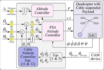
The overall control architecture of the system, as implemented in this work, is shown in Fig. 3. The controller is designed based on the linearized dynamics of the system with the assumption of cable remains taut. Hence, for stable and smooth payload transportation and avoid aggressive maneuvers, bounds on the higher-level commands are imposed as
 $\phi_h, \theta_h \in [-45^\circ\,\, 45^\circ]$
,
 $\dot{\psi}_h \in [-45^\circ\,\, 45^\circ]/\textrm{s}$
,
 $\dot{z}_h \in [-250 \,\,\, 250]\,\textrm{cm/s}$
. Further, as PX4 autopilot attitude controller is defined based on linear PID controller its inputs,
 $(\phi_d, \theta_d)$
are bounded in the region
 $[-45^{\circ}\,\, 45^{\circ}]$
for stability point of view. The higher-level commands
 $(\phi_h, \theta_h, \dot{\psi}_h, \dot{z}_h)$
can be planned either using on-board sensors for localization and obstacle avoidance to enable fully autonomous flight or can be supplied directly from the human operator using RC remote control joystick or can be a combination of these two modalities to present a semi-autonomous flight. The CAC commands
 $(\phi_c, \theta_c)$
are calculated on-board PX4 autopilot at
 $100\, \textrm{Hz}$
, where CAM device provides the real-time cable attitude feedback.
Overall control architecture of the system, where (
 $\phi_h, \theta_h, \dot{\psi}_h, \dot{z}_h$
) are higher level commands. Using cable attitude measured by CAM device in frame
 $\{B\}$
, that is,
 $\phi_{p,_{CAM}}, \theta_{p,_{CAM}}$
, and IMU data, the cable attitude and its rate in frame
 $\{I\}$
, that is, (
 $\phi_p, \dot{\phi}_p, \theta_p, \dot{\theta}_p$
) are estimated using Eqs. (1 & 5) in PX4 autopilot. Cable attitude controller calculates
 $\phi_c$
and
 $\theta_c$
using Eqs. (11 & 12), and these commands are added to
 $\phi_h$
and
 $\theta_h$
, respectively. The desired yaw angle is calculated by integrating the yaw rate command,
 $\dot{\psi}_h$
. On-board PX4 autopilot attitude controller generates required moment,
 $\boldsymbol{M}$
, that tracks the desired attitude of the quadcopter. The desired altitude,
 $z_d$
, is calculated by integrating
 $\dot{z}_h$
and using altitude controller Eq. (13), thrust force, F, is applied to the system

3. Outdoor Experiments
Two sets of outdoor experiments with the quadcopter-payload system are presented in this section. In the first set of experiments, out of four higher level commands,
 $(\phi_h,\, \theta_h)$
commands are computed using on-board GPS sensor and other two commands
 $(\dot{\psi}_h, \dot{z}_h)$
are taken from the human operator using RC remote control joystick. In second set of experiments, all the four higher level commands are taken from the human operator using RC remote control joystick. As per the proposed control modality, out of the four commands, (
 $\phi_h$
,
 $\theta_h$
,
 $\dot{\psi}_h$
,
 $\dot{z}_h$
), CAC commands, (
 $\phi_c$
,
 $\theta_c$
), are only supplemented to (
 $\phi_h$
,
 $\theta_h$
) to plan the desired values of (
 $\phi_d$
,
 $\theta_d$
). Accordingly, within each set of experiments, a comparison is presented between the cases when CAC is not used, that is,
 $\phi_c = \theta_c = 0$
, and when it is used to control the cable attitude. To make comparison between these two cases, 3D trajectory traced by the quadcopter is estimated using a GPS sensor, quadcopter’s roll and pitch angles (
 $\phi$
,
 $\theta$
) are estimated using PX4 autopilot’s IMU, and cable attitude (
 $\phi_p$
,
 $\theta_p$
) are estimated using CAM device. Further, higher level commands (
 $\phi_h$
,
 $\theta_h$
) are estimated using GPS sensor by Eqs. (11-12) in first set of experiments and using RC remote control joystick in second set of experiments. All the experimental data were logged on the PX4 autopilot.
3.1. Semi-autonomous flight
In this experiment, the commands (
 $\phi_h,\,\,\theta_h$
) are computed using an on-board GPS sensor that provides the quadcopter’s latitude and longitude information in real-time. Using standard ECEF (Earth-Centered, Earth Fixed) coordinate system, quadcopter’s translational positions, (x, y), and velocities, (
 $\dot{x}$
,
 $\dot{y}$
) are calculated. The task involved in this experiment was to navigate the system through four set-points located at the corners of a square path separated by
 $10\,\textrm{m}$
at a height of
 $10\,\textrm{m}$
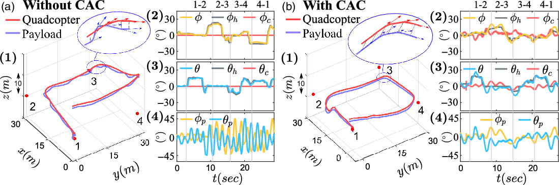
from the ground. This is shown by points 1-2-3-4-1 in Fig. 4(A.1, B.1). The tuned gains of the on-board set-point navigation control allowed a maximum velocity of
 $2.5\,\textrm{m/s}$
along two directions. During the experiment, when the system hovered at an altitude between
 $10\pm3 \,\textrm{m}$
, the pre-programmed on-board set-point navigation control mode was activated remotely by RC remote control joystick. The human operator supplied
 $\dot{z}_h$
commands to maintain the height of the system at
 $10\,\textrm{m}$
. Further, the yaw rate command,
 $\dot{\psi}_h$
, was not required for executing this task and was kept at zero.
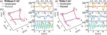
The experimental results for semi-autonomous flight. Plots (A) show when CAC is not implemented and plots (B) show when CAC is implemented. (1) 3D trajectory traced by the quadcopter and payload. The system started its motion from point 1 and followed a path 1-2-3-4-1. The distance between each plots is
 $10\,\textrm{m}$
. (2) show quadcopter roll angle,
 $\phi$
, human roll command,
 $\phi_h$
, CAC roll command,
 $\phi_c$
. (3) show quadcopter pitch angle,
 $\theta$
, human pitch command,
 $\theta_h$
, and CAC pitch command,
 $\theta_c$
. (4) show the cable attitude,
 $\phi_p,\theta_p$

The experimental results are shown for without CAC case in Fig. 4(A) and for with CAC case in Fig. 4(B). The output of the set-point navigation control, (
 $\phi_h$
,
 $\theta_h$
) commands, and quadcopter roll and pitch, (
 $\phi$
,
 $\theta$
), are shown in Fig. 4(A.2, A.3) and (B.2, B.3). It is observed that (
 $\phi$
,
 $\theta$
) values followed (
 $\phi_h$
,
 $\theta_h$
) commands very closely for without CAC case compared to with CAC case. This is because, in the CAC case, the quadcopter response is as per (
 $\phi_h$
,
 $\theta_h$
) and non-zero CAC, (
 $\phi_c$
,
 $\theta_c$
), commands. From Fig. 4(A.1) and (B.1), it is observed that the overall quadcopter maneuver was closer to the desired square trajectory in the CAC case compared to without CAC case. Notably, the variations in the payload position relative to quadcopter were higher for without CAC case. This implies that the quadcopter-payload system deviates from its intended trajectory when navigation commands
 $(\phi_h, \theta_h)$
are planned on-board without incorporating the countermeasures to minimize the payload oscillations.
From the logged data of the flight the relative position of the payload from the quadcopter during the flight along (
 $\boldsymbol{e}_{\boldsymbol{1}}$
,
 $\boldsymbol{e}_{\boldsymbol{2}}$
,
 $\boldsymbol{e}_{\boldsymbol{3}}$
) axes are computed as (
 $-2.66 \pm 24.29\,\textrm{cm}$
,
 $-0.97 \pm 34.15\,\textrm{cm}$
,
 $-90.49 \pm 6.84\,\textrm{cm}$
) for without CAC case and (
 $-3.68 \pm 13.16\,\textrm{cm}$
,
 $-1.59 \pm 27.62\,\textrm{cm}$
,
 $-94.92 \pm 6.84\,\textrm{cm}$
) for with CAC case. In particular, it is noted that the percentage reductions in the standard deviation of the payload’s relative position along (
 $\boldsymbol{e}_{\boldsymbol{1}}$
,
 $\boldsymbol{e}_{\boldsymbol{2}}$
) axes are about (
 $46 \%$
,
 $20 \%$
) for the CAC case compared to without CAC case. Moreover, the payload was on an average of
 $94.92\,\textrm{cm}$
from the quadcopter along
 $\boldsymbol{e}_{\boldsymbol{3}}$
axis when CAC was used, which is much closer to the length of
 $l = 100\,\textrm{cm}$
used for suspending the payload during the experiment. From Fig. 4(A.4) and (B.4), a notable reduction is observed in the cable attitude values (
 $\phi_p$
,
 $\theta_p$
), for with CAC case compared to without CAC case. In general, the mean and standard deviation in (
 $\phi_p$
,
 $\theta_p$
) values are around (
 $-1.54 \pm 14.35 ^\circ$
,
 $-0.65 \pm 21.07^\circ$
) for without CAC case and (
 $-2.26 \pm 7.66 ^\circ$
,
 $-0.95 \pm 16.86 ^\circ$
) for with CAC case. Using Fast Fourier transform (FFT) analysis, the dominant frequency component of the payload altitude (
 $\phi_p$
,
 $\theta_p$
) are (
 $0.55\, \textrm{Hz}$
,
 $0.51 \,\textrm{Hz}$
) for without CAC case and (
 $0.1 \,\textrm{Hz}$
,
 $0.17\, \textrm{Hz}$
) for with CAC case respectively. These observations indicate a significant reduction in the payload oscillations when CAC commands were supplemented to the commands of the on-board set-point navigation control.
Overall, the semi-autonomous flight experiments successfully demonstrate the use of CAM device to provide on-board cable attitude feedback and CAC implementation to minimize the payload oscillations during the flight.
3.2. Human-controlled flight
In this experiment, a human operator fully controlled the quadcopter-payload system by applying four commands, (
 $\phi_h$
,
 $\theta_h$
,
 $\dot{\psi}_h$
,
 $\dot{z}_h$
) remotely using RC remote control joystick. The task for this experiment was to fly the system along a square path in the horizontal plane with
 $30\, \textrm{m}$
sides as indicated by points 1-2-3-4-1 in Fig. 5(A.1) and (B.1). Indicators for these points were provided on the ground as a reference of the square path to the human operator during the experiment. Considering the task in the horizontal plane, the operator mainly applied (
 $\phi_h$
,
 $\theta_h$
) commands. The flight was performed at an appropriate altitude between
 $10\pm 3\,\textrm{m}$
from the ground, which if required was maintained using
 $\dot{z}_h$
command. Further, as the yaw rate,
 $\dot{\psi}_h$
, command particularly alters the quadcopter’s heading angle, it was not required for executing this task.
The experimental results for human-controlled flight. Plots (A) show when CAC is not implemented and plots (B) show when CAC is implemented. (1) 3D trajectory traced by the quadcopter and payload. Point 1 is marked at which human operator starts the task. Points 2, 3, 4 are marked at the corners of the
 $30\, \textrm{m} \times 30\, \textrm{m}$
square path at the same altitude as point 1. (2) Quadcopter’s roll angle,
 $\phi$
, human roll command,
 $\phi_h$
, and CAC roll command,
 $\phi_c$
. (3) Quadcopter’s pitch angle,
 $\theta$
, human pitch command,
 $\theta_h$
, and CAC pitch command,
 $\theta_c$
. (4) Cable attitude, (
 $\phi_p, \theta_p$
)

The experimental result are shown for without CAC case in Fig. 5(A) and for with CAC case in Fig. 5(B). To follow a square path, the human operator specified the roll and pitch commands, (
 $\phi_h$
,
 $\theta_h$
), simultaneously to turn the system at the corners as shown in Fig. 5(A.2, A.3) and (B.2, B.3). For the human-controlled flight, even though, the exact tracking of the desired square path with reference on the ground is quite challenging, it is observed that the human operator flew the system closer to the path in both cases, as in Fig. 5(A.1) and (B.1). However, the variations in the payload position relative to the quadcopter were higher for without CAC case, which also affected the overall flight maneuver. This implies that applying countermeasures to minimize payload oscillations can be effective for human-controlled flights of a quadcopter-payload system.
It is observed from Fig. 5(A) and (B) that with the use of CAM device and CAC, the overall human-controlled flight performance and experience improved. In particular, quadcopter followed the human commands (
 $\phi_h$
,
 $\theta_h$
) very closely in without CAC case, as seen in Fig. 5(A.2, A.3). In contrast, in with CAC case, CAC commands (
 $\phi_c$
,
 $\theta_c$
) minimize the payload oscillations during the flight, quadcopter’s rolling and pitching motion (
 $\phi$
,
 $\theta$
) varied about (
 $\phi_h$
,
 $\theta_h$
), as in Fig. 5(B.2, B.3). Further, to execute the quadcopter-payload flight in without CAC case, human operator supplied commands instantaneously and of large amplitudes seen as discrete steps in Fig. 5(A.2, A.3), which were to change the flight direction and to compensate for payload oscillations. Due to the coupled dynamics of the system, abrupt quadcopter motion induced payload oscillations, which in turn require human operator to apply compensatory responses. In contrast, the implementation of CAC in with CAC case supplied (
 $\phi_c$
,
 $\theta_c$
) commands to reduce the payload oscillation along with the human commands. This implementation resulted in smoother quadcopter and payload motion and elicited relatively continuous human commands of lower magnitude during the flight as seen in Fig. 5(B.2, B.3).
From the logged data of the flight the relative position of the payload from the quadcopter along (
 $\boldsymbol{e}_{\boldsymbol{1}}$
,
 $\boldsymbol{e}_{\boldsymbol{2}}$
,
 $\boldsymbol{e}_{\boldsymbol{3}}$
) axes are (
 $1.27 \pm 30.87\, \textrm{cm}$
,
 $8.66 \pm 29.31\, \textrm{cm}$
,
 $89.58 \pm 9.88\,\textrm{cm}$
) for without CAC case and (
 $3.44 \pm 16.16\, \textrm{cm}$
,
 $9.08 \pm 19.25\,\textrm{cm}$
,
 $96.24 \pm 3.95\,\textrm{cm}$
) for with CAC case. Compared to without CAC case, the percentage reductions in the standard deviation of payload’s relative position along (
 $\boldsymbol{e}_{\boldsymbol{1}},\, \boldsymbol{e}_{\boldsymbol{2}},\, \boldsymbol{e}_{\boldsymbol{3}}$
) axes in with CAC case are about (47%, 34%, 60%) during the flight. Moreover, the vertical distance between the quadcopter and payload was on an average
 $96\, \textrm{cm}$
in with CAC case, which is closer to the cable length of
 $l = 100\, \textrm{cm}$
, as compared to
 $89\, cm$
in without CAC case. Essentially, these data show that the payload remains quite underneath the quadcopter when CAC is implemented.
Notable change can also be observed in the payload oscillations from the variations of (
 $\phi_p$
,
 $\theta_p$
) in Fig. 5(A.4) and (B.4) during the flight. The mean and standard deviation values in (
 $\phi_p$
,
 $\theta_p$
) are around (
 $0.69\pm 18.95^\circ$
,
 $ -5.6 \pm 19.03^\circ$
) in without CAC case and (
 $1.98 \pm 9.3^\circ$
,
 $-5.43\pm 11.39^\circ$
) in with CAC case. Thus, the percentage reduction in the standard deviation is about (
 $50.6 \%$
,
 $40.1\%$
) in (
 $\phi_p$
,
 $\theta_p$
), respectively, when CAC is implemented. Moreover, using Fast Fourier transform (FFT) analysis, the dominant frequency component of the payload altitude (
 $\phi_p$
,
 $\theta_p$
) is (
 $0.56\, \textrm{Hz}$
,
 $0.6 \,\textrm{Hz}$
) for without CAC case and (
 $0.11\, \textrm{Hz}$
,
 $0.17 \,\textrm{Hz}$
) for with CAC case respectively. It essentially indicates that with the use of CAC the payload oscillates at a lower frequency. These observations indicate attenuated payload oscillations when CAC commands were supplemented with human commands.
Essentially, with the implementation of CAC, the payload consistently maintains its position underneath the quadcopter, which can be a simpler approach to execute impromptu payload transportation tasks in outdoor settings. This is further highlighted in the enlarged view of the quadcopter-payload trajectory by the translational velocity vectors immediately before and after the turn at Point 3, refer Fig. 5(A.1) for without CAC case and Fig. 5(B.1) for with CAC case. Payload’s velocity vectors point in different directions and vary abruptly with respect to quadcopter’s vectors in without CAC case compared to with CAC case. As payload oscillates at high frequency and with a large amplitudes in without CAC case, considerable change in its velocity and, consequently, momentum is expected at the corners of the square trajectory or whenever quadcopter changes directions. As a result, a large reactive force acts on the quadcopter resisting its motion, which requires the operator to apply large and sudden inputs to maintain a path. In contrast, the use of CAC helps in reducing oscillations magnitude and frequency, which imply comparatively smaller reactive force on the quadcopter. Thus, the operator is mainly required to send commands to maneuver along a path, and a comparatively smoother flight is observed.
Overall, the experimental results of human-controlled flight successfully demonstrate the capability of the proposed modality of using an on-board CAM device to estimate the cable attitude, an-board implementation of CAC to minimize the payload oscillations, and incorporating humans’ cognitive ability to navigate a quadcopter-payload system in the outdoor settings.
3.3. Case study
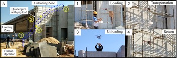
A case study is conducted at a real construction site to demonstrate the feasibility of the proposed modality in impromptu object transportation. The task considered in the case study is to transport a brick-sized object (mass
 $82\, \textrm{gm}$
) from the ground to the roof of a
 $40\, \textrm{ft}$
tall building. For simplicity, a snap hook is used to attach and detach the payload with the quadcopter via a cable originating at the CAM device’s lever.
The overall transportation process is shown in Fig. 6(A). An operator first flies the quadcopter to the loading zone, where a construction worker attaches the object by the hook, as shown in Fig. 6(1). The operator then commands the system to transport the object to the unloading zone, as shown in Fig. 6(2). During the flight, any oscillations produced in the object are attenuated by the implemented CAC, providing a smoother flying experience to the operator. At the unloading zone, another construction worker unloads the object as shown in Fig. 6(3) after which the operator flies the quadcopter back to the loading zone to transport more objects.
(A) Overall steps of aerial transportation of object at a real construction site, Snapshots: (1) worker loads the object, (2) human operator transport the payload, (3) worker at roof unloads the object, and (4) human operator returns the quadcopter at loading zone

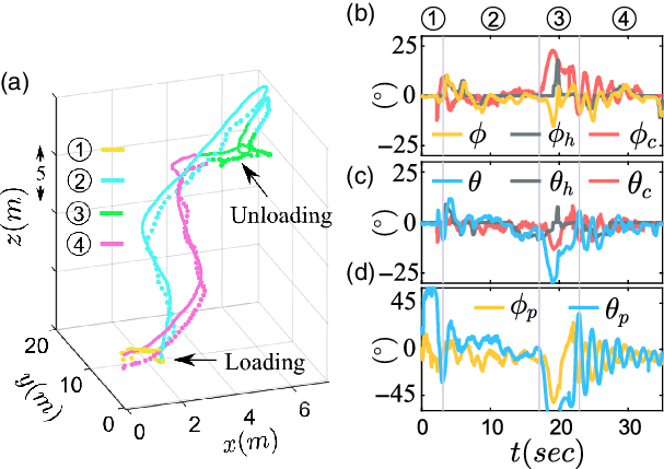
Corresponding experimental results of the presented case study are shown in Fig. 7. The 3D trajectory followed by the quadcopter and payload with indication of four processes are shown in Fig. 7(a) and commanded roll and pitch commands, (
 $\phi_h$
,
 $\theta_h$
) are shown in the Fig. 7(b) and (c). During loading and unloading, the worker grabs the hook to attach or detach the payload, leading to a large payload attitude as can be observed in Fig. 7(d) for the processes (1) and (3). Consequently, CAC supplied appropriate (
 $\phi_c\,\, \theta_c$
) commands, Fig. 7(b) and (c), to result in quadcopter rolling and pitching movements to attenuate the payload oscillations. Accordingly, as observed in Fig. 7(d), the oscillations of the payload are rapidly reduced.
Experimental results of conducted case study. (a) 3D trajectory followed by the quadcopter and payload. Quadcopter’s path is shown as solid line and payload’s path is shown as dotted line. (b) Quadcopter’s roll angle,
 $\phi$
, human roll command,
 $\phi_h$
, and CAC roll command,
 $\phi_c$
. (c) Quadcopter’s pitch angle,
 $\theta$
, human pitch command,
 $\theta_h$
, and CAC pitch command,
 $\theta_c$
. (d) Cable attitude, (
 $\phi_p$
,
 $\theta_p$
)

3.4. Discussion and future work
The presented experimental results and case study show the performance of CAC and CAM device in effectively reducing the payload oscillations and, consequently, minimizing the operator’s effort required for maneuvering the system. Thus, the proposed modality is easily deployable to perform impromptu object transportation tasks safely and smoothly.
In particular, the image processing techniques proposed in literature [Reference Gassner, Cieslewski and Scaramuzza30, Reference Bisgaard31, Reference Tang, Wüest and Kumar32] to estimate the cable attitude are subjected to higher computation cost with a limited rate of about
 $50\,\textrm{Hz}$
. Also, the accuracy of these techniques depends on the outdoor lighting conditions and necessity of using cues and tags for payload detection. In contrast, CAM device is a mechanical sensor, and its performance is not limited by similar constraints. Moreover, CAM device being portable achieves on-board sensing and cable attitude estimation at a rate of
 $760\, \textrm{Hz}$
. The current work demonstrates that the CAM device can reliably be used to compute payload oscillation measure for outdoor flight.
Various control modalities such as geometric controller [Reference Sreenath, Lee and Kumar14, Reference Zeng, Kotaru and Sreenath18, Reference Lee, Sreenath and Kumar27], input shaping [Reference Guo and Leang23], reinforcement learning [Reference Faust, Palunko, Cruz, Fierro and Tapia25, Reference Faust, Palunko, Cruz, Fierro and Tapia26], and admittance controller [Reference Tagliabue, Kamel, Verling, Siegwart and Nieto34, Reference Tagliabue, Kamel, Siegwart and Nieto35] have been adopted in the literature to attenuate the payload oscillations. Although the presented CAC is based on a proportional-derivative controller, the experimental results highlight that CAC successfully minimizing the cable oscillations and keeps it underneath the quadcopter, leading to a smooth flight. However, it is noted that the performance of the CAC can be further improved to enable the practical use of the proposed modality. In particular, non-linear and adaptive control schemes can be implemented that guaranteed stability under external disturbances, changes in the mass of the payload and length of the cable for better performance. Additionally, the problems related to the cable slackness will be resolved in future works by detecting cable slacking in real-time, as presented in [Reference Tang and Kumar19].
Human supervision plays an important role in the applications such as aerial surveillance, search and rescue operations for applying higher level commands as mentioned in [Reference Vergouw, Nagel, Bondt and Custers40, Reference Perez-Grau, Ragel, Caballero, Viguria and Ollero41]. In this context, we presented a human-in-the-loop control strategy that successfully demonstrates smooth outdoor aerial transportation of suspended payload using CAM device and CAC. In the future, for a thorough evaluation of the presented modality, studies will be conducted with multiple subjects with rigorous experiment protocols that emulate real-world scenarios.
4. Conclusion
The current work demonstrates human-controlled aerial transportation of a cable-suspended payload using a quadcopter in outdoor settings. To achieve this, a state feedback controller named cable attitude controller (CAC) is successfully implemented to minimize the payload oscillations for stable and smooth transportation. Further, on-board portable device, cable attitude measurement (CAM) device is developed to measure the cable attitude in real-time, enabling on-board implementation of CAC. Two sets of outdoor experiments, semi-autonomous flight and human-controlled flight, and a case study at a real construction site successfully illustrate the feasibility of the presented modality for outdoor aerial transportation applications.
Acknowledgement
This work is supported by Core Research Grant (CRG/2020/004990) from SERB India.
Appendix
The expressions for matrices
 ${\boldsymbol{\mathcal{M}}(\boldsymbol{s})} \in \mathbb{R}^{5 \times 5}, {\boldsymbol{C} (\boldsymbol{\textit{s,}} \dot{\boldsymbol{s}})} \in \mathbb{R}^{5\times5}$
, and
 ${\boldsymbol{G}(\boldsymbol{s})} \in \mathbb{R}^{5 \times 1}$
are given below,
 \begin{equation*} {\boldsymbol{\mathcal{M}} (\boldsymbol{s})} = \left[\begin{array}{c@{\quad}c@{\quad}c@{\quad}c@{\quad}c}m_t & 0 & 0 & 0 & -m_p \gamma\\[4pt]0 & m_t & 0 & \\[-2pt] & & & \ \ \ \ \ \quad {\boldsymbol{M}^{\boldsymbol{T}}_{\boldsymbol{t}}}\!\!\!\!\!\! \!\!\! \\[-2pt]0 & 0 & m_t & \\[4pt]0 & & & m_p \gamma^2 & 0\\[-2pt]& \quad {\boldsymbol{M}_{\boldsymbol{t}}}\!\!\!\!\!\! \!\! &&\\[-2pt] - m_p \gamma & & & 0 & m_p {l^{2}}\end{array} \right]\end{equation*}
where,
 $m_t = m + m_p$
,
 $\gamma = {l} c \theta_p$
, and
 $ {\boldsymbol{M}_{\boldsymbol{t}}} = \begin{bmatrix} m_p {l} c\phi_p c \theta_p & \quad m_p {l} s\phi_p c\theta_p\\[4pt]-m_p {l} s\phi_p s\theta_p & \quad m_p {l} c\phi_p s\theta_p\end{bmatrix}_{2 \times 2}$
.
 \begin{equation*} {\boldsymbol{C}(\boldsymbol{\textit{s,}}\dot{\boldsymbol{s}})} = \left[\begin{array}{c@{\quad}c@{\quad}c}\vdots & 0 & m_p {l} s\phi_p\dot{\theta}_p\\[3pt]& {C_1} & -m_p {l} s\phi_p c\theta_p\dot{\theta}_p \\[3pt] \boldsymbol{0}_{5 \times 3} & m_p {l} c\theta_p c\phi_p\dot{\phi}_p & {C_2}\\[3pt] & 0 & -m_p {l^2} s(2\theta_p) \dot{\phi}_p\\[3pt]\vdots & m_p {l^2} c\theta_p s\theta_p\dot{\phi}_p &0\end{array}\right]\end{equation*}
where,
 ${C_1} = -m_p {l} s\phi_pc\theta_p\dot{\phi}_p - 2m_p {l} c\phi_p s\theta_p\dot{\theta}_p$
, and
 ${C_2} = - 2m_p {l} s\phi_p s\theta_p \dot{\phi}_p + m_p {l} c\phi_p c\theta_p \dot{\theta}_p$
 \begin{equation*} {\boldsymbol{G}(\boldsymbol{s})} = \begin{bmatrix}\boldsymbol{0}_{2 \times 1} \\[3pt] m_t g \\[3pt] m_p g {l} s\phi_p c\theta_p \\[3pt] m_p g {l} c\phi_p s\theta_p \end{bmatrix}\end{equation*}