Introduction
Adhesively bonded joints are increasingly becoming an alternative to mechanical joints in engineering applications and provide many advantages over conventional mechanical fasteners. Among these are lower structure weight, lower fabrication cost, and improved damage tolerance.Reference Banea and da Silva1–Reference Budhe, Banea, de Barros and da Silva3 Design flexibility and joining of dissimilar or new advanced materials are also benefits of adhesive joints.
Most of today’s industrial structures consist of combinations of different materials (e.g., steel, aluminum, magnesium, fiber-reinforced plastics, and sandwich structures) in order to provide the best performance. Adhesives can be used to join metals, polymers, ceramics, cork, rubber, and combinations of any of these materials.Reference Banea, Da Silva, Campilho and Sato4 However, these materials need to be joined according to their specific characteristics. For example, metal–plastic combinations are used in structures to combine the high specific stiffness and strength of metals with the high degree of design freedom of polymer composites.
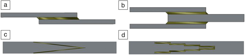
Different materials and joint geometries give rise to distinct stress states in the adhesive layer, and the performance of adhesive joints depends on several factors (e.g., the joint geometry and the mechanical properties of the adhesive and adherends). There are a wide variety of joints available to the designer. Common joint configurations used in structures include single-lap joints (SLJs), double-lap joints, scarf joints, and stepped-lap joints (Figure 1). Many other configurations exist, with specific advantages, such as peel joints, the joggle-lap joints and L-section joints among others.Reference Banea and da Silva1 However, the SLJ is the most common joint used and studied today mainly due to its simplicity and efficiency.
Examples of configurations of adhesively bonded joints. (a) Single-lap joint. (b) Double-lap joint. (c) Double scarf joint. (d) Double stepped-lap joint.

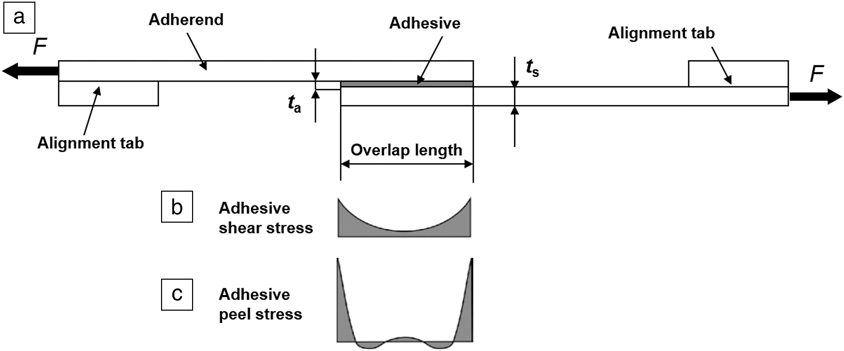
The SLJ (Figure 2) consists of two rectangular adherends bonded together by an adhesive. End (alignment) tabs, cut from the same material as the adherends, are often adhesively bonded to the specimens to reduce (not eliminate) the eccentricity of the load path. Thus, due to the load misalignment, which occurs even when alignment tabs are used, and due to the differential adhesive straining effect,Reference Volkersen5 the adhesive is subjected to a state of nonuniform shear and peel stresses (Figure 2b–c). Tension stresses arise in the adhesive due to peel, cleavage, or tensile loading of joints and can also occur in shear loaded joints due to bending moments resulting from the eccentricity of the loading, illustrated for single-lap joints in Figure 2c. These stresses result in failure of the adhesive before the shear stresses are fully developed so that the theoretical maximum joint strength is not attained. In addition, the bending moments and tension stresses may result in yielding in metallic and thermoplastic substrates, which may also limit joint strength. Peel strength can be described as a material’s ability to resist forces that can pull or peel it apart at a predetermined angle and rate. The ASTM D1002 standard recommends reporting the results of SLJ tests as the average shear stress at failure (maximum load divided by bond area).Reference da Silva, Carbas and Banea6
Single-lap joint. (a) Joint configuration. (b) Adhesive shear stress distribution along the overlap; and (c) adhesive peel stress distribution along the overlap. Note: t a, adhesive thickness; t s, adherend thickness; F, applied load.

This article summarizes the effects of adherend properties on adhesively bonded joint strength. The main parameters affecting the strength of adhesively bonded joints are discussed. Several methods that have been used to predict failure in bonded joints are briefly described. Example applications of these methods are presented to illustrate recent advances in the numerical modeling of the effect of adherend on the strength of adhesive joints.
Effects of adherend properties on adhesive joint strength
The main parameters affecting the strength of adhesively bonded joints are the joint geometry and the mechanical properties of adhesive and adherends.Reference da Silva, Carbas and Banea6 The adherends materials influence the performance of adhesively bonded joints, and its effect should be considered in the design of adhesive joints. For example, adherend yielding might occur in structures where metals such as aluminum or mild steel are used. On the other hand, unlike isotropic adherends, laminated composite adherends have relatively low transverse strength and shear stiffness compared to their in-plane material properties, and it is, therefore, important to understand the mechanisms of failure involved for each specific material.
Most published work examines the influence of adherend stiffness on the joint strength where, in general, increasing the adherend stiffness improved the joint´s strength.Reference Kafkalidis and Thouless7–Reference Banea, da Silva, Carbas and Campilho12 Also, it was shown that in joints with yielding adherends, failure is ruled by the adherend yielding.Reference Kafkalidis and Thouless7,Reference Banea, da Silva, Carbas and Campilho12 The effect of adherend material on the mechanical behavior of adhesive joints was investigated experimentally and numerically in SLJs with different adherend materials (high-strength [HS] steel, low-strength steel, and composite).Reference Banea, da Silva, Carbas and Campilho12 For relatively short overlaps in SLJs bonded with structural modern tough adhesives (e.g., SikaForce7888, used in the automotive industry), failure is dominated by adhesive global yielding (failure occurs when a path of adhesive along the overlap region reaches the state in which it cannot sustain a further significant increase in applied load), and the influence of adherend material on joint strength is not significant. For longer overlaps, failure no longer occurs due to adhesive global yielding, and the effect of the adherend material becomes more important. Moreover, it was possible to evaluate which adhesive is more suited for a specific material.
Adherends can have different flexural stiffnesses due to either geometric or material considerations. For low-strength adherends, an increase in thickness is beneficial; the adherend becomes less likely to deform plastically. For high-strength adherends, however, a greater thickness can decrease the joint strength due to an increase in the bending moment.
The effects of different material combinations on the strength of dissimilar bonded joints has been extensively investigated.Reference Banea, da Silva, Carbas and Campilho12–Reference Machado, Nunes, Marques and da Silva28 Owens and Lee-SullivanReference Owens and Lee-Sullivan13,Reference Owens and Lee-Sullivan19 studied the behavior of composite/aluminum joints and developed an analytical model to predict joint stiffness loss with crack growth. They found that flexible adhesives increase resistance to crack growth, thus increasing the joint strength. RudawskaReference Rudawska29 performed experimental and numerical studies on joints between different adherend materials (titanium, aluminum alloys, and aramid–epoxy composites). The joint strength varied depending on the chosen adherend combination, with the best results for aluminum–aluminum joints. Avedaño et al.Reference Avendaño, Carbas, Marques, da Silva and Fernandes30 investigated the joint strength of SLJs composed of dissimilar lightweight adherends (unidirectional carbon fiber-reinforced polymer composite and an environmentally friendly biopolymer) under quasistatic and impact loading as a function of temperature (e.g., −30, +23, and +80°C). They found a significant decrease in joint strength at 80°C. The prolonged exposure or even short term exposure to elevated temperatures will often produce irreversible chemical and physical changes within adhesives, such as decreasing bond strength with increasing temperature.Reference Banea and da Silva1
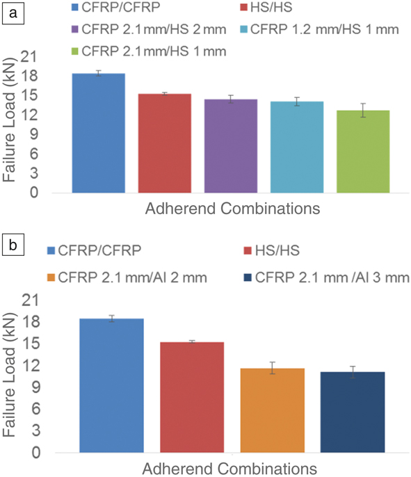
More recently, Banea et al.Reference Banea, Rosioara, Carbas and da Silva31 experimentally and numerically investigated multimaterial adhesive joints using various combinations of adherends (HS steel, aluminum [Al], and carbon fiber-reinforced plastics [CFRPs]) bonded with a modern tough structural adhesive (SikaForce7888) used in the automotive industry. The multimaterial joints studied were divided into geometrically balanced joints (t s1 = t s2) and stiffness-balanced joints (E 1t s1 = E 2t s2, where E 1 and E 2 are Young’s moduli and t s1 and t s2 are the adherend thicknesses of the joint adherends). From Figure 3a, it can be observed that geometrically balanced joints (CFRP [1.2 mm]/HS [1 mm] and CFRP [2.1 mm]/HS [2 mm]) promote higher strength than the stiffness-balanced joints (CFRP [2.1 mm]/HS [1 mm]). This is due to the fact that unbalanced geometrical joints (stiffness-balanced joints) cause large rotation and displacements arising from the bending moment induced by the eccentricity of the load axis. A decrease in adherend thickness for CFRP (e.g., from 2.1 mm to 1.2 mm) did not promote a significant decrease in joint strength, thus a reduction of mass can be achieved without losing joint efficiency (with the highest values of failure loads). Similar strength behavior was observed for CFRP/Al joints, where CFRP [2.1 mm]/Al (2 mm performed better than stiffness-balanced CFRP [2.1 mm]/Al [3 mm] joints), as seen from Figure 3b. It was concluded that geometrical multimaterial balanced joints promote a higher strength than the stiffness multimaterial balanced joints. The most efficient joint was that composed of similar CFRP adherends, becoming less so for dissimilar adherends, particularly for the case of unbalanced geometrical joints (i.e., CFRP [2.1 mm]/HS [1 mm]), as can be seen in Figure 3.Reference Banea, Rosioara, Carbas and da Silva31
The effect of material combination on the failure load of single-lap joints.Reference Banea, Rosioara, Carbas and da Silva31 (a) Failure loads of similar joints (CFRP/CFRP, HS/HS) and CFRP/HS dissimilar joints. Similar joints had the highest failure load values while geometrically balanced joints (CFRP [1.2 mm]/HS [1 mm] and CFRP [2.1 mm]/HS [2 mm]) show higher strength than the stiffness-balanced joints (CFRP [2.1 mm]/HS [1 mm]). (b) Failure loads of similar joints (CFRP/CFRP, HS/HS) compared to CFRP/Al dissimilar joints. As CFRP/HS dissimilar joints in (a), geometrically balanced CFRP (2.1 mm)/Al (2 mm) joints withstand higher loads before failing as compared to stiffness-balanced CFRP [2.1 mm]/Al [3 mm] joints). Note: CFRP, carbon fiber-reinforced plastics; HS, high-strength steels.

Another important parameter that influences the performance of adhesively bonded joints is the adhesive thickness.Reference Banea, Da Silva and Campilho32 For SLJs, studies show that, in general, the joint strength decreases as the adhesive thickness increases, with the exception of SLJs bonded with elastomeric adhesives.Reference Banea and Da Silva33,Reference Banea and da Silva34 The highest strength is obtained for adhesive thicknesses on the order of 0.1–0.5 mm.Reference da Silva, Rodrigues, Figueiredo, de Moura and Chousal35,Reference Gleich, Van Tooren and Beukers36 Moreover, this observation is not generally applicable as there are other factors involved, such as the type of loading, the adherend behavior (elastic or plastic), and the type of adhesive (ductile or brittle), which can modify the behavior of joints as the adhesive thickness is varied.Reference Banea, Da Silva and Campilho32
The overlap length (Figure 2) can also affect joint strength in SLJs.Reference Banea and Da Silva37 While increasing the joint width increases the strength proportionally, the effect of the overlap length on the adhesive joint strength depends on the type of adhesive (i.e., ductile or brittle) and also on the type of adherends.Reference Banea, da Silva, Carbas and Campilho12 For instance, for bonded joints with elastic adherends and ductile adhesives, the joint strength is proportional to the overlap length. This occurs because ductile adhesives deform plastically as the load increases and make use of the whole overlap. In this case, the global yielding failure criterion is suitable. For joints with elastic adherends and brittle adhesives, the joint strength is not proportional to the overlap length, and a limited strength is attained. In this case, the adhesive does not accommodate peak stresses at the ends of the overlap (Figure 2), and failure is ruled by these peaks.
For composite adherends, the overlap effect on the strength of the joints is mainly dictated by the composite transverse strength.Reference Neto, Campilho and Da Silva38 One of the issues in bonding composite adherends is delamination, due to the fact that composites are made of stacked layers. This is particularly true if the composite adherends are made of layers with different fiber orientations. It is well known that along the longitudinal fiber direction, unidirectional composites can be strong and stiff, whereas its transverse and shear properties are much lower. Thus, to avoid premature failure of composite adherends, it is recommended to orient the outer layers of the composite adherend parallel to the loading direction.
Modeling the effect of adherend on strength of adhesive joints
In order to design structural joints in engineering structures, it is necessary to be able to analyze them; this means to determine stresses and strains under a given loading condition and to predict the probable points of failure. There are two basic mathematical approaches for the analyses of adhesively bonded joints—closed-form analysis (analytical methods) and numerical methods (i.e., FEM).Reference Banea and da Silva1,Reference Banea39
The analysis of adhesive joints began almost 90 years ago with the closed-form model of VolkersenReference Volkersen5 that considered fully elastic materials and adhesive deformation only in shear. However, the analytical formulation of adhesive joints becomes more complex if the adhesive deforms plastically, if composite adherends are used, or if dissimilar adherend materials (e.g., composites with plastic metals) are used. FEM has been employed for strength prediction, traditionally by using stress/strain or fracture mechanics criteria. These techniques showed acceptable results but have some limitations: stress/strain methods are mesh dependent, while fracture criteria are restricted to linear elastic fracture mechanics and rely on the existence of an initial crack.
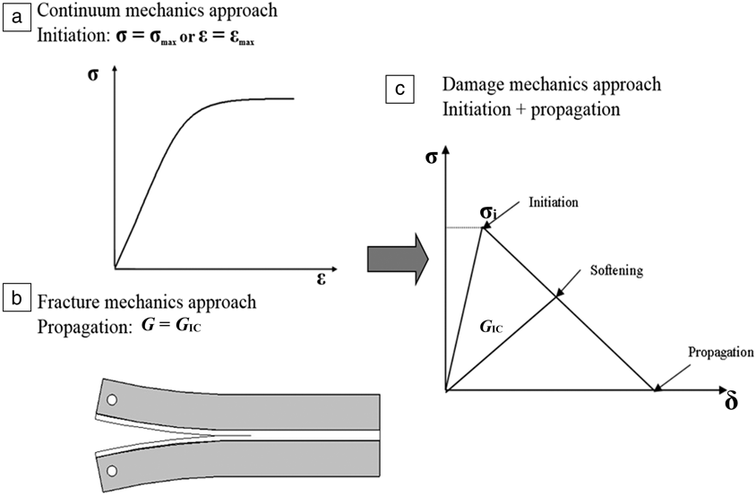
One method that surpasses these limitations is CZMs. This method has received considerable attention in the last few years and has been employed for a wide variety of problems and materials, including metals, ceramics, polymers, and composites. A CZM models the fracture process, extending the concept of continuum mechanics by including a zone of discontinuity modeled by cohesive zones, thus using both strength and energy parameters to characterize the debonding process along the crack path (Figure 4), allowing the approach to be of much more general utility than conventional fracture mechanics. CZMs may be used for adhesive debonding or for composite delaminations, when composite adherends are used. The main difference in CZMs is in the shape of the traction-separation curves and the parameters that describe this shape. In general, the parameters that describe the cohesive law are the area under the traction-separation curve (the toughness), and a characteristic strength (typically, the cohesive strength) or a characteristic displacement that represents the failure strain of the cohesive zone.Reference Banea and da Silva1,Reference Banea39
Schematic of a cohesive zone model for failure prediction of adhesively bonded joints. (a) Continuum mechanics approach: a crack initiates when the maximum values of stress or strain are attained. (b) Fracture mechanics approach uses an energy parameter (toughness) as the failure criterion. (c) Traction-separation law with linear elastic interface behavior: with increasing interfacial separation, the traction across the interface reaches a maximum (crack initiation), then decreases (softening) until crack propagation causes complete debonding of the interfaces. Note: σ, tensile stress; σmax, tensile strength at failure; σi, strength (tensile, shear); δ, separation; ε, tensile strain; εmax, tensile strain at failure; G, energy release rate; G IC, mode I critical energy release rate.Reference Banea39

However, cohesive models present a limitation, as it is necessary to know in advance the critical zones where damage is prone to occur and place the cohesive elements in accordance. Continuum damage models constitute a valuable alternative when a crack path is not known in advance. Also, continuum damage models acquire special relevancy when the adhesive thickness must be considered.Reference Banea39
A series of tests and CZM simulations of adhesive joints between similar and dissimilar adherend materials have been conducted.Reference Banea, da Silva, Carbas and Campilho12,Reference Anyfantis and Tsouvalis14,Reference Fernandes, Campilho, Banea and Da Silva40 AnyfantisReference Anyfantis and Tsouvalis14 modeled the joints between CFRP composites and steel bonded with a ductile adhesive layer. The elastoplastic loading and fracture response were modeled by a recently developed mixed-mode CZM law. Recently, Banea et al.Reference Banea, da Silva, Carbas and Campilho12 experimentally and numerically investigated the effect of adherend materials on the fracture behavior of adhesive joints bonded with modern tough structural adhesives (a two-component structural polyurethane adhesive, SikaForce7888, and a one-component structural epoxy-polyurethane adhesive, SikaPower4588). SLJ tests with various adherend materials (HS steel, low-strength steel, and composite) were performed. In addition to the experimental work, numerical analysis by FEM, based on CZM, was conducted. A bilinear cohesive damage model was used to obtain numerical predictions as a function of material for each adhesive. For short overlaps (e.g., 12.5 and 25 mm), the CZM returned consistent predictions for both adhesives as a function of material. It has been reported in the literature that for short overlaps, the joint strength is more dependent on the adhesive strength.Reference Karachalios, Adams and da Silva8,Reference Karachalios, Adams and da Silva9 For larger overlaps, modern ductile adhesives permit plasticization at the overlap edges, whereas the inner bondline increases its contribution to the joint strength. However, for a 50-mm overlap length, the numerical results exhibit different trends, depending on the material and adhesive. For the Sikaforce7888, the numerical results compare well for hard steel adherends, but under predict the experiments for composite adherends. In contrast, for SikaPower4588 joints, the model overestimates the results for polymer composite adherends and produces satisfactory results for hard steel adherends. This can be explained by the fact that a triangular law was used even though the behavior of ductile adhesives is closer to a trapezoidal shape. The triangular law was used because it is implemented in commercial finite element analysis software (e.g., Abaqus), while the trapezoidal law is in not used and needs user subroutines. In addition, fracture parameters (toughness) for the adherend material are important to consider in the model.
Summary
New engineering applications are increasingly composed of a combination of advanced materials, which need to be joined according to their specific characteristics. Adhesives can be used to join metals, polymers, ceramics, cork, rubber, and combinations of these materials. The adherend properties have an important effect on the bonded joint strength. Generally, increasing the adherend stiffness improves the joint strength. The higher the adherend stiffness, the smaller is the deformation at the overlapping ends of the joint, and the lower is the effect of differential straining in the adhesive.
In joints with yielding adherends (e.g., mild and medium carbon steel, aluminum), failure is ruled by the adherend yielding, and a steady-state value is attained in the maximum load versus overlap plot, corresponding to the adherend yielding. In this case, the influence of adhesive type and overlap length is not significant, as the joint strength is dominated by the adherend plasticity.
For bonded joints with elastic adherends (e.g., HS steel) and ductile adhesives, strength is roughly proportional to the overlap length. This is because ductile adhesives deform plastically as the load increases and make use of the whole overlap. In this case, the global yielding failure criterion is suitable. For joints with elastic adherends and brittle adhesives, the joint strength is not proportional to the overlap, and a limit strength is attained. This occurs because the adhesive does not accommodate peak stresses at the ends of the overlap, and failure is ruled by these peaks. Finally, for composite adherends, the strength of the joints is mainly dictated by the composite transverse strength. It is well known that bonded joints experience peel loading, so the composite adherend will probably fail in transverse tension before the adhesive fails.
Adhesive joints with similar adherends are more efficient than joints with dissimilar adherends. The use of dissimilar adherends decreases the joint strength due to nonuniform stress distribution (the highest stresses are at the side of the less-stiff adherend, owing to a higher axial strain). However, geometrically dissimilar balanced joints promote higher strength than the stiffness dissimilar balanced joints.
A good failure criterion should predict both failure mode as well as failure load. However, accurate prediction of the joint strength has thus far been limited by the lack of a suitable, universally applicable failure criterion and insufficient accuracy in calculating the stresses and strains in the adhesive layer. These need to be further explored.
Acknowledgments
The author would like to acknowledge the support of the Brazilian Research Agencies, CNPq and FAPERJ.

Mariana D. Banea is currently a professor at the Federal Center for Technological Education of Rio de Janeiro, Brazil. She received her PhD degree in mechanical engineering at the University of Porto, Portugal, in 2011. From 2012 to 2015, she completed postdoctoral research at the Institute of Mechanical Engineering, Faculty of Engineering, at the University of Porto. Her research focuses on adhesive bonding and composite materials. Banea’s awards include the SAGE Best Paper Award and the Donald Julius Groen Prize, both in 2010, from the Institution of Mechanical Engineers, UK. She has also received the António de Almeida Foundation (Portugal) Award in 2013. Banea can be reached by email at mdbanea@gmail.com.