1. INTRODUCTION
Improving the efficiency of microwave generators and amplifiers is a key challenge in high-power pulsed microwave electronics (Korovin et al., Reference Korovin, Kurkan, Loginov, Pegel, Polevin, Volkov and Zherlitsyn2003), in which the power of individual oscillators today approaches 1010 W. New methods to increase the efficiency of power conversion from driving electron beam to microwave emission arising from fundamentally non-steady-state, transient effects, for example, superradiance (Eltchaninov et al., Reference Eltchaninov, Korovin, Rostov, Pegel, Mesyats, Rukin, Shpak, Yalandin and Ginzburg2003) allowed production of extremely short (subnanosecond) gigawatt pulses using very compact devices. However, as the duration of these pulses is small, so is the pulse energy usually amounting to few Joules. That is why it is still practically valuable to improve the efficiency of “conventional” high-power microwave (HPM) sources generating relatively long pulses (tens of nanoseconds and more) with greater energy. It is also important that, in the sources operating in repetitively pulsed mode, reducing the energy of electrons in the spent electron beam lowers the thermal load on the collector (and therefore the cooling requirements), and, to an even greater extent, reduces the collector bremsstrahlung and the requirements for X-ray protection.
Among the devices with rectilinear relativistic electron beams operating in long-pulse (quasi-stationary) mode, the highest efficiencies are predicted for klystron-type devices, in which the energy extraction region is separated from the area of beam modulation by inertial bunching section. One such device is twistron having the energy extraction section with a traveling wave with an amplitude growing along the longitudinal coordinate. Theoretical analysis of the electron–wave interaction in a relativistic twistron demonstrated that the electron efficiency of the device can reach 60% (Kovalev et al., Reference Kovalev, Kolchugin and Krotova1975).
The aim of the present work was to study and optimize in numerical experiment a relativistic twistron driven by a high-current electron beam of moderate power (electron energy ~300 keV, beam current ~3 kA), which is typically generated in a nanosecond high-current electron accelerator (Mesyats et al., Reference Mesyats, Korovin, Gunin, Gubanov, Stepchenko, Grishin, Landl and Alekseenko2003) of medium or compact class.
A convenient starting point for these studies is another relativistic microwave device with a straight electron beam, previously proposed and thoroughly studied: Čerenkov microwave oscillator based on the design of relativistic backward wave oscillator (RBWO) with a modulating reflector (Korovin et al., Reference Korovin, Kurkan, Rostov and Totmeninov1999). We can say that this device already possesses some klystron features because it contains a modulator and a section for inertial bunching, although the energy extraction occurring in its output section [which is a slow-wave structure (SWS)] is due to the same mechanism as in a “classical” RBWO. We demonstrate that, nominally keeping the morphology of the device, we can realize in it a fundamentally different (typical for a twistron) amplitude and phase characteristics, achieving higher radiation efficiency than in an RBWO.
2. PROBLEM FORMULATION
In an RBWO with a modulating reflector, the radiofrequency (RF) electric field in the reflector area causes energy modulation in the injected electron beam, which arrives more or less bunched to the input of the SWS. Previously, it was demonstrated that variation of the bunching distance (the drift section length), effecting the amplitude and phase relationships between the RF current and the field of the synchronous wave at the inlet of the SWS, allows wide-range control of the generation frequency (Totmeninov et al., Reference Totmeninov, Klimov, Kurkan, Polevin and Rostov2008) and efficiency (Korovin et al., Reference Korovin, Kurkan, Rostov and Totmeninov1999).
To implement the twistron mode of the device, the following conditions are advisable to perform. First, it is necessary to provide in the region, where the energy extraction from the beam is most intense, in-phase oscillation of most intense field harmonics, which are the 0th harmonic of forward traveling wave and − first harmonic of the backward wave (assuming that this harmonic is synchronous with the beam electrons). Second, the electron bunches must reach maximum compactness at the entrance of this region. Third, the length of the energy extraction area should be small in order to avoid reversion of the energy exchange, which might be caused by both kinematic effects in the beam and destruction of the electron bunches by Coulomb repulsion forces (this repulsion is accompanied by formation of low- and high-energy electron fractions (Pegel, Reference Pegel1996) falling out of Čerenkov synchronism condition).
3. OSCILLATOR DESIGN
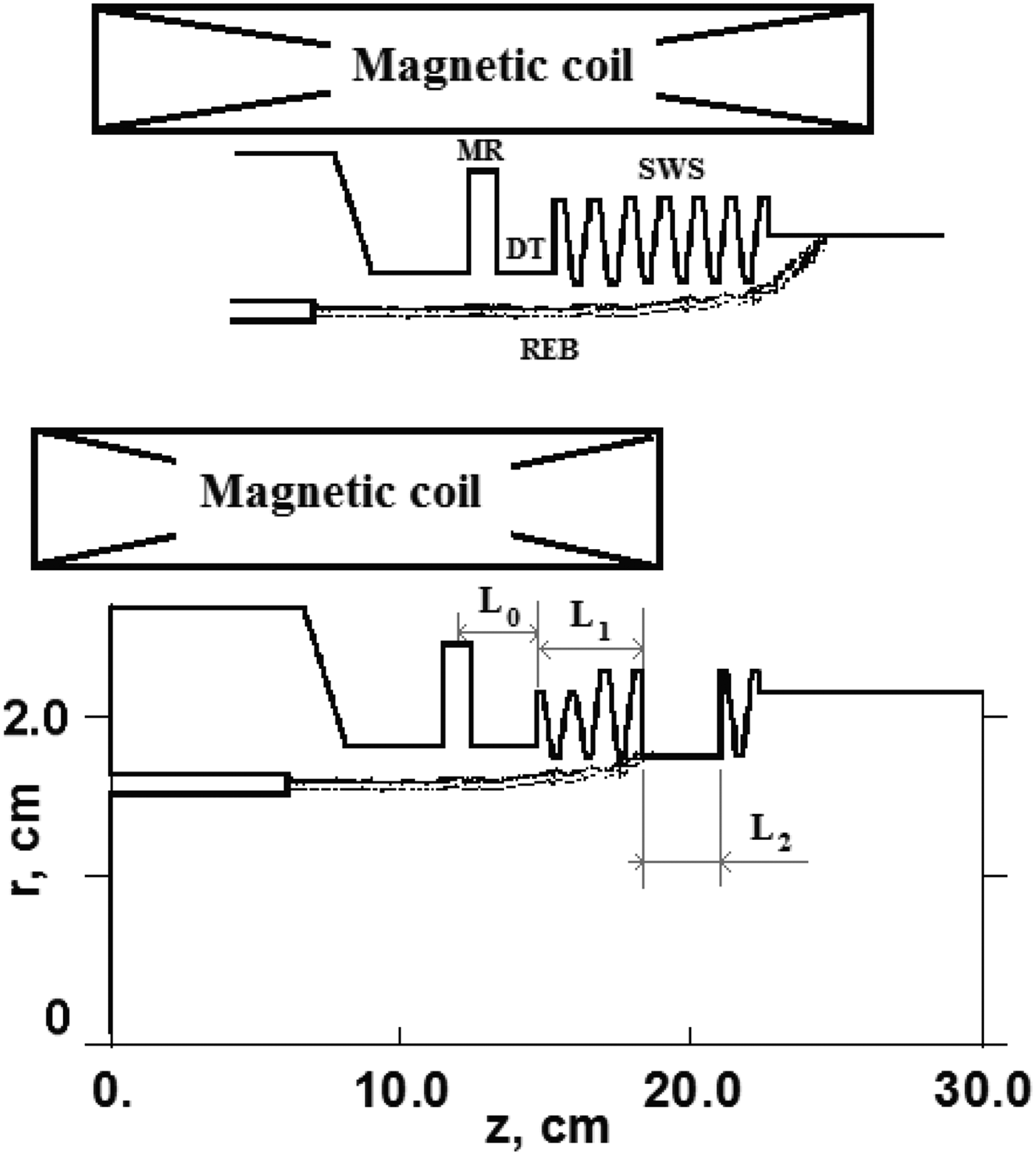
Alike in the RBWO with a modulating reflector (Fig. 1, top), the key element of the proposed generator (Fig. 1, bottom) is the reflector-modulator. The reflector position relative to the SWS sets the amplitude and phase relationships between RF current in the electron beam and the fields of main harmonics at the SWS inlet.
Above: typical configuration of RBWO with a modulating reflector (MR, modulating reflector; DT, drift tube (bunching space); REB, tubular relativistic electron beam); bottom: configuration of the device proposed.

Earlier, an expression was obtained for the current modulation phase, which determines the position of central electron in the bunch with respect to longitudinal electric field of −1st harmonic at the entrance to the SWS assuming the SWS corrugation starts with maximum radius (Korovin et al., Reference Korovin, Kurkan, Rostov and Totmeninov1999):
 $$\arg ({\rm \alpha} ) \approx - \displaystyle{{\rm \pi} \over 2} - \left( {k\displaystyle{{L_0} \over {{\rm \beta} _{//}}} + hL_0} \right) + 2{\rm \pi} m,\quad m = 0,1, \ldots. $$
Here, h is the longitudinal wave number of TM01 wave between the reflector and the SWS inlet, L 0 is the length of this interval, and β// is the longitudinal velocity of electrons in the units of speed of light in vacuum). The first term in the expression is the phase difference (in the central plane of the reflector) between RF field of the reflector cavity and RF field of the backward wave (at that, −π/2 corresponds to middle of accelerating phase of the backward wave). So far as the backward wave is reflected in idle mode (Korovin et al., Reference Korovin, Kurkan, Rostov and Totmeninov1999), we can write a similar expression for the fundamental (0th) harmonic of the forward wave:
 $$\arg ({\rm \beta} ) \approx \displaystyle{{\rm \pi} \over 2} + \left( {k\displaystyle{{L_0} \over {{\rm \beta} _{{\rm //}}}} - hL_0} \right) + 2{\rm \pi} n,\quad n = 0,1, \ldots. $$
This parameter determines the position of central electron in the bunch (at the entrance of SWS) relative to longitudinal field of 0th harmonic of the forward wave.
Thus, changing the distance L 0 allows controlling the bunch phasing at the entrance of the SWS.
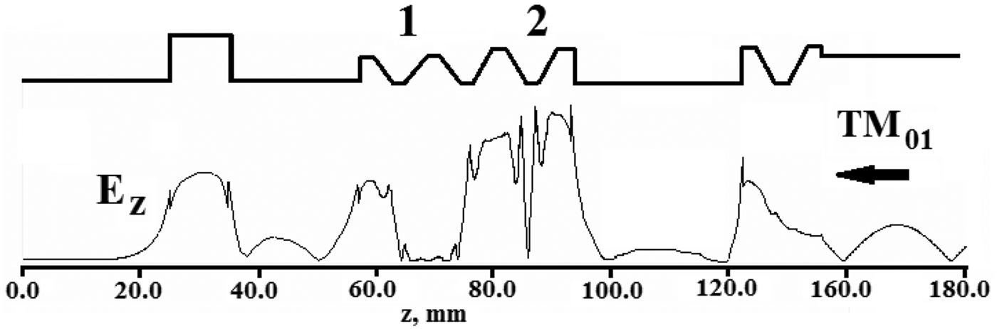
Next, it is advisable to choose the location of electron beam deposition where the electron bunches reach maximum compactness. It is also appropriate that the slope of the SWS at this location is nearly perpendicular to electron trajectory. In this case, the electric field acting on electrons is represented by z-component only (the calculated longitudinal dependence for this component is in Fig. 2).
“Cold” longitudinal distribution of electric field z-component at 9.7 GHz at the radius of the electron beam (16 mm) calculated using a program based on a scattering matrix method (Denisov et al., Reference Denisov, Lukovnikov and Samsonov1995). 1 and 2 denote parts of the SWS with smaller and larger corrugation depths.

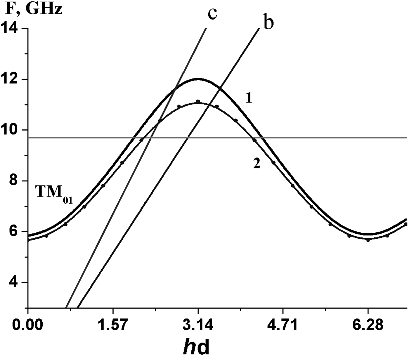
Figure 3 shows the dispersion curves of the operating wave in SWS Sections 1 and 2 (Fig. 2) calculated in the approximation of infinitely long-corrugated waveguide.
Dispersion relations for Sections 1 and 2 of the SWS (Fig. 2): d, corrugation period, c, “speed of light” line, and b, “electron beam” line.

4. NUMERICAL MODELING
The main part of the simulations employed the axisymmetric version of KARAT code (Tarakanov, Reference Tarakanov1992). Earlier, this code has been intensively used in the development of different types of microwave generators (Kitsanov et al., Reference Kitsanov, Klimov, Korovin, Kurkan, Pegel and Polevin2002; Totmeninov et al., Reference Totmeninov, Klimov, Kurkan, Polevin and Rostov2008, Reference Totmeninov, Kitsanov and Vykhodtsev2011). Additionally, a one-dimensional particle-in-cell (1D PiC) model (Pegel, Reference Pegel1996) has been applied taking into account the wave harmonics mentioned above and the effect of space charge in the electron beam. To evaluate the beam coupling to the basic wave harmonics, a program based on the method of scattering matrices was applied (Denisov et al., Reference Denisov, Lukovnikov and Samsonov1995).
Numerically optimizing the electrodynamic structure of the device allowed converting 56% of the beam power into TM01 electromagnetic wave (Fig. 4). Herewith, the “electronic efficiency” calculated by the decrease in the kinetic energy of electrons with regard to their energy in the transport channel in front of the reflector was as high as 66% (Fig. 5).
Simulated non-averaged waveform of microwave power (above), and the radiation spectrum of the generator with accelerating voltage 340 kV, beam current 3.3 kA, and guiding magnetic field 2.2 T. The microwave power is 630 MW at 9.7 GHz and < 5 MW at higher harmonics.

Upper graph: dimensionless kinetic energy of electrons versus longitudinal coordinate [(1) saturated steady-state oscillation; (2) prior to oscillation buildup] and the “electronic efficiency” η = (E − E 0)/E 0 obtained in KARAT simulation. Below: dimensionless kinetic energy (3) and “electronic efficiency” (4) obtained in 1D PiC model. All presented values are averaged over RF oscillation period.

For 9.7 GHz generation frequency and with L
0 = 27 mm as it was set in the modeling we have
 $\arg ({\rm \alpha} ) \approx 0$
and
 $\arg ({\rm \beta} ) \approx 1.4{\rm \pi} $
. This means that at the entrance of the SWS the central electron in the bunch gets into transition from decelerating phase to accelerating phase of the synchronous −1st spatial harmonic of the backward wave, and near the middle of accelerating phase of 0th harmonic of the forward wave. The kinematic offset of the electron relative to 0th harmonic of the forward wave along the interval L
1 = 36 mm from the SWS entrance up to the beam dumping position is
 $\Delta {\rm \phi} _0 = kL_1(1/{\rm \beta} _{{\rm //}} - 1/{\rm \beta} _{{\rm ph},0}) \approx {\rm \pi} $
(here, βph,0 ≈ 1.14 is dimensionless phase velocity of 0th harmonic in the SWS). Then
 $\arg ({\rm \beta} ) + \Delta {\rm \phi} _0 \approx 2.4{\rm \pi} $
. Consequently, at the end of the interaction space, the central electron gets into braking phase of the forward wave. At the same time, it is always in the decelerating phase of −1st harmonic of backward wave, since the electron velocity β// ≈ 0.77 exceeds the phase velocity of the harmonic βph,−1 ≈ 0.6. Thus, near the beam dump, the decelerating RF field is represented by an in-phase sum of 0th harmonic of forward wave and −1st harmonic of backward wave having the coupling impedance to the beam Z
0 ≈ 3.5 Ω and Z
−1 ≈ 2.7 Ω, respectively.
With such a phasing, the energy exchange between the beam and the RF field is non-monotonous along the interaction space (Fig. 5). The electron bunch is first boosted by the field of 0th harmonic of forward wave. As a result, it is shifted to the center of decelerating phase of −1st harmonic of the backward wave. The kinetic energy of the bunch is extracted by RF field on a short section (with a length close to corrugation period), and the intensity of the extraction achieves its maximum near the beam dumping location, where the beam coupling to longitudinal RF field is maximized due to steep (normal) tilt of the SWS surface.
Figure 6 demonstrated that an electron bunch is perfectly compact at the moment of its deposition onto SWS surface (snapshot at 35.16 ns) and it does not leave the decelerating phase of the RF field until dumping. Here, there is an additional positive effect caused by electron beam space charge due to the fact that the space-charge field additionally accelerates electron bunches approaching the SWS surface before dumping while they lose their velocity under the action of intense RF field. Hence, the bunch is retained in the braking phase of the RF field and its potential energy is converted into radiation energy.
Longitudinal distribution of beam current, grayscale map of RF electric field strength (z-component) for different moments of time, and the phase plot of the electron beam, demonstrating very moderate amount of backward electrons (PiC simulation using KARAT code; total number of particles ~30,000).

Changing of length L 2 of the smooth waveguide section results in a periodic variation in the generation power and oscillation buildup time. The corresponding period is 21 mm, which is close to half of wavelength of TM01 wave in this waveguide. In the regimes with maximum generation power (620–630 MW), the oscillation buildup time reaches its minimum 15–18 ns.
The HPM generator is rather adaptive to variation of electron beam parameters. With electron beam power increased from 0.9 to 1.4 GW, the microwave power grew from 460 to 700 MW, while the efficiency of the device did not descend below 50%.
5. CONCLUSION
In the HPM device proposed, the following segments are distinguished along the device length: the space for electron beam energy modulation (reflector area); the bunching space; the section of bunch phase correction (first half of SWS), and the section for energy extraction (part of the SWS immediately in front of the beam dump). Herewith, the beam bunching gradually develops all the way from the reflector to the dumping site. Since the energy extraction from the beam occurs mainly in a short final segment of the SWS and it is primarily due to the field of forward traveling wave, this device may be classified as relativistic twistron (Kovalev et al., Reference Kovalev, Kolchugin and Krotova1975).
ACKNOWLEDGMENT
The authors would like to thank Dr. A. I. Klimov for valuable discussions.