









Introduction
In recent years, unmanned aerial vehicles (UAVs) have been increasingly deployed in various fields such as environmental monitoring, agricultural inspection, firefighting, and communication system deployment [Reference Fernández González, Padilla, Valenzuela-Valdes, Padilla and Sierra-Perez1]. In UAV ground control stations, image transmission is typically achieved using antennas operating at  $5.8$ GHz [Reference Alyassi, Khonji, Karapetyan, Chau, Elbassioni and Tseng2–Reference Qin, Han, Zhang, Mao and Zhu4], which are designed to overcome communication challenges caused by weather changes and harsh environments. To ensure stable communication links, the antennas are required to provide broadband, circular polarization (CP), and reduce the side lobe level (SLL). Several structural designs have been proposed to meet these demands.
Some asymmetric coplanar waveguide (CPW) and patch antennas have been designed to enhance the impedance bandwidth. For example, integrating antennas with a defected ground structure has achieved a bandwidth of 7.7 $\%$ with a low voltage standing wave ratio (VSWR) [Reference Yang, Yanzhu, Yuan, Cao and Wang5]. Other designs, such as using circular Y-shaped antennas with parasitic patches, have been proposed, but did not consider CP [Reference Balderas, Reyna, Panduro, Rio and Gutiérrez6]. Although some studies integrated linearly polarized arrays to achieve the axial ratio (AR) [Reference Araña-Pulido, Jiménez-Yguácel, Cabrera-Almeida and Quintana-Morales7], their limited AR bandwidth can compromise signal reliability in certain scenarios.
To reduce SLL, various feeding networks such as Dolph-Chebyshev, Taylor, and Binomial have been explored [Reference Nie, Wen, Kai-Da, Luo, Yang and Zhou8–Reference Kalva and Kumar10]. Feeding networks can be classified into series and parallel configurations. Series structures lack adjustable port amplitude ratios, whereas parallel structures tend to be complex and bulky [Reference Yin, Wu, Chen, Wang and Hong11]. A hybrid feeding network that integrates both series and parallel structures is a common strategy. For example, a spatial phase antenna design with radiating patches on the front and a feeding network with phase-gradient and amplitude-tapered structures on the back demonstrated effective SLL  $\leq$-30 dB, although with an excessively wide main lobe [Reference Dong, Cai and Wen12].
In this letter, a hybrid feeding network is proposed. The phase-gradient network controls the feed phases to improve radiation directivity and achieve higher gain. Meanwhile, the amplitude-tapered network optimizes the distribution of feed amplitudes to enhance energy focusing and suppress SLL. Additionally, this work focuses specifically on the use of omnidirectional antennas for the ground station to enhance UAV image transmission performance, ensuring a stable communication link by avoiding nulls in certain directions. All simulations in this work were performed using full 3D EM simulation software.
The remainder of this article is organized as follows. The Design and evaluation of hybrid feeding networks section presents the design and optimization of the hybrid phase-amplitude feeding networks. The Results and analysis section presents the results and their analysis. Finally, the Conclusion section summarizes the study.
Design and evaluation of hybrid feeding networks
Design and optimization of the phase-gradient ring feeding network
As shown in Fig. 1, the four patches are rotated  $90^{\circ}$ around their centers, creating a positional phase difference. A phase-shifting ring feed adds a spatial phase difference, and together they enhance the AR bandwidth. Three quarter-ring sections of varying widths provide phase shifting and impedance matching, ensuring 50
 $\Omega$ output at each port[Reference Penchala Reddy Sura, Rajvee and Kumar13]. A sensitivity analysis was conducted using HFSS at
 $5.8$ GHz to assess the impact of each structural parameter on S11 and CP performance, identifying
 $lmd4$ as the most critical. Using HFSS, optimization was performed with targets of S11 bandwidth
 $5.3\sim6.1$ GHz (below
 $-15$ dB) and AR bandwidth
 $5.3\sim5.8$ GHz (below
 $3$ dB), with
 $lmd4$ in the range
 $5\sim11mm$ and the Sequential Nonlinear Programming algorithm with up to
 $100$ iterations. After
 $93$ iterations, the optimal value
 $lmd4 = 7.5mm$ was obtained.
Radiation patch with phase-gradient feeding ring.

Figure 2(a) and (b) shows the variations of S11 and AR bandwidths with  $lmd4$. At
 $lmd4 = 7.5mm$, the antenna achieves the widest bandwidths, S11 spans
 $5.39\sim5.91$ GHz, and AR spans
 $5.49\sim5.58$ GHz. Although
 $5.8$ GHz is not at the center of ranges, further optimization is needed to fully meet UAV communication requirements.
Antenna with phase-gradient feeding ring. (a) S11. (b) AR.

Therefore, four radiating patches are integrated with the ring structure through coaxial feeds. The dimensions are optimized through simulation  $W_{50} = 2.4 mm$,
 $lmd4 = 7.5 mm$,
 $r_{1} = 5.94 mm$,
 $r_{2} = 2.23 mm$,
 $r_{3} = 1.7 mm$,
 $r_{4} = 1.088 mm$,
 $rt = 1.2 mm$,
 $c=2.22 mm$,
 $Wp=15.32 mm$.
Analysis and improvement of amplitude-tapered feeding network
For UAV image transmission systems, suppression of interference signals received through antenna sidelobes is achieved by implementing low SLL designs. As demonstrated in Fig. 3, three types of feeding networks are mentioned. The type I utilizes a  $4\theta$ electrical length resistor to construct an equal amplitude feeding network. The type II incorporates resistors of
 $\theta$ and
 $3\theta$ electrical length to establish an unequal amplitude feeding network. The type III consists of four resistors with an electrical length of
 $\theta$. In addition,
 $Z_{in}$ and
 $Z_{L}$ represent the equivalent impedance of the input network and antenna unit.
Different feeding types of structures.

For SLL suppression in the antenna, the Chebyshev polynomial is implemented to achieve unequal-amplitude current distribution in the antenna ports. The current amplitude ratios are as follows.
 \begin{equation}
I_{5\left ( 4 \right ) } : I_{6\left ( 3 \right ) } : I_{7\left ( 2 \right ) } : I_{8\left ( 1 \right ) }=1:0.81: 0.52: 0.26
\end{equation}
The normalized current amplitude presented in Fig. 4, which demonstrates that type I maintains the same amplitude characteristics in all ports, while types II and III strictly adhere to the distribution pattern specified in Eq. (1). Through the performance evaluation in Table 1.
Current amplitude. Down triangle( $I_{4}/I_{5}$), up triangle (
 $I_{3(6)}/I_{4(5)}$), circle (
 $I_{2(7)}/I_{4(5)}$), and square(
 $I_{1(8)}/I_{4(5)}$).

Bandwidth under different elements and types

BW is impedance bandwidth.
The type III configuration is identified as exhibiting optimal characteristics in the  $8$-element configuration, achieving a superior bandwidth ratio of
 $96.8\%$.
The proposed phase-coherent feeding network with amplitude-tapered feeding introduces improvements over the design in [Reference Lyu, Zhu and Cheng14]. As shown in Fig. 5, the feeding network is centrally symmetric, with resistor names and electrical lengths labeled on the left and widths on the right. To minimize the area occupied by the feeding network and avoid unnecessary coupling, the input ports of the feeding network employ coaxial feeds. Four resistors form a compact type III network, and the bandwidth is listed in Table 1. The input impedance  $Z_{f}$ is matched to
 $50\Omega$ by adjusting
 $Z_{m1}$ and
 $Z_{m2}$, which provide the right input impedance of NET1. Based on Equations (1-4), after calculating
 $Z_{in}$, the values of
 $Z_{m1}$ and
 $Z_{m2}$ are obtained using impedance transformation as follows.
 \begin{equation}
k_{1}=I_{6(3)}/I_{5(4)},k_{2}=I_{7(2)}/I_{6(3)},k_{3}=I_{8(1)}/I_{7(2)}
\end{equation}
 \begin{equation}
Z_{in}=\frac{Z_{L}}{1+k_{1}^2+k_{1}^2k_{2}^2+k_{1}^2k_{2}^2k_{3}^2}
\end{equation}
 \begin{equation}
Z_{m2}=\sqrt{z_{f}\times50},Z_{m1}=\sqrt{Z_{in}\times Z_{m2}}
\end{equation}
Identification of feed network models and physical dimensions.

The dimensional and resistor distribution of the feeding network is presented in the following.  $Z_{0} = 1.0234\times Z_{L} = 51.17\Omega$,
 $Z_{1} = \sqrt{k_{1}} \times Z_{0} = 46.11\Omega$,
 $Z_{2} = \sqrt{k_{2}} \times Z_{0} = 40.9\Omega$,
 $Z_{3}=\sqrt{k_{3}}\times Z_{0}=36.38\Omega$,
 $Z_{in}=25.04\Omega$,
 $Z_{m1} = 35.39\Omega$ and
 $Z_{m2} = 70.74\Omega$. Furthermore, dimensional parameters
 $W_{50}= 2.4 mm$,
 $W_{0} = 2.07 mm$,
 $W_{1} = 3.42 mm$,
 $W_{2} = 2.9 mm$,
 $W_{3}= 2.43 mm$,
 $W_{4} = 3.56 mm$,
 $W_{5} = 1.19 mm$ and
 $D=64 mm$.
Based on  $\theta = 90^{\circ}$, the length of each resistor corresponds to a quarter wavelength. Due to slight differences in resistance values, the calculated quarter-wavelength lengths have multiple decimal places. For ease of fabrication and considering the relatively low operating frequency, the lengths were rounded to two decimal places, resulting in
 $L_5 = 8.89 mm$,
 $L_4 = 8.50 mm$,
 $L_0 = 8.69 mm$,
 $L_3 = 8.63 mm$,
 $L_2 = 8.57 mm$, and
 $L_1 = 8.51 mm$.
The phase performance is demonstrated in Fig. 6(a), it can be seen that the phase traces of the feeding network ports are not completely uniform, but they strictly maintain the periodic phase relationship of  $N\times360^{\circ}$ (
 $N=1,2,3,...,n$) and ensure the phase consistency of all ports.
Response of amplitude-tapered feeding network models. (a) Outport phase response. (b) Output amplitude response.

The normalized current amplitude ratios of Fig. 6(b) are measured as
 \begin{equation}
I_{5\left ( 4 \right ) } : I_{6\left ( 3 \right ) } : I_{7\left ( 2 \right ) } : I_{8\left ( 1 \right ) }=1:0.77: 0.52: 0.36.
\end{equation}
Equation (5) shows deviations from the theoretical values predicted by Eq. (1). These discrepancies are attributed to signal cancellation effects caused by opposing currents in cross-aligned ports. Although amplitude variations result in slightly degraded sidelobe suppression, the optimal antenna spacing configuration is considered of greater significance.
Antenna array realization and performance evaluation
Figure 7 shows the side view, in which the three-layer structure is fabricated on three identical dielectric substrates with a thickness of  $0.8 mm$. The multilayer dielectric stacking enables the bandwidth extension while maintaining a low profile.
Antenna structure layout.

In Fig. 8(a), the non-rotating subarray with a red circle suffers from current coupling between the patches and the feeding branches, leading to degraded CP. In contrast, the rotated array marked by a black circle avoids such interference. As shown in Fig. 8(b), the rotated array exhibits a wider AR bandwidth than the non-rotating case.
Effect of subarray rotation. (a) Surface current. (b) AR.

The superior S-parameters range from  $2.39\sim7.47$ GHz, with a fractional bandwidth of
 $87.5\%$. The 3 dB AR bandwidth spans from
 $5.1\sim6.0$ GHz, fully contained within the impedance bandwidth, as shown in Fig. 9.
Simulated results of the antenna. (a) S11 and AR. (b) Gain.

A maximum gain of  $19.59$ dBi is achieved at
 $\theta = 0^{\circ}$, with SLL
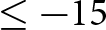
 $\leq -15$ dB and a half-power beamwidth (HPBW) of
 $25.14^{\circ}$.These characteristics meet all UAV image transmission requirements while maintaining stable directional performance across the operating band.
Designed specifically for ground UAV control stations, this directional antenna array ensures reliable communication and enhanced performance in dynamic flight scenarios.
Results and analysis
The physical prototype is shown in Fig. 10, with overall dimensions of  $310mm \times140mm\times2.4 mm$. During assembly, nylon screws were inserted through the alignment holes to ensure precise layer registration and firm fixation. The fabricated antenna was tested in a microwave anechoic chamber, as illustrated in Fig. 10, and the measurement results are discussed in detail as follows. The S-parameters of the antenna are shown in Fig. 11(a). The measured impedance bandwidth of
 $2.3\sim7.4$ GHz is in concordance with the simulated results of
 $2.39\sim7.47$ GHz. Minor discrepancies are attributed to non-ideal soldering conditions between the SMA connector and the antenna array.
Testing the array in a microwave anechoic chamber and prototype of the array.

The AR bandwidth and gain are compared in Fig. 11(b), showing the measured  $5.14\sim6.0$ GHz and the simulated
 $5.1\sim6.0$ GHz. The peak gain obtained by the actual measurement is
 $18.26$ dBi, and the simulation is
 $19.59$ dBi. The slight reduction is caused by the fabrication misalignment in the three-layer substrate, leading to incomplete current transfer.
Simulated and measured results of the proposed antenna. (a) S11. (b) AR and gain.

Figure 12 shows the measured and simulated radiation patterns of the antenna at  $5.6$,
 $5.8$ and
 $6.0$ GHz, in the XOZ and YOZ planes for both RHCP and LHCP. In Figure 12(a), the RHCP main beam dominates with well-suppressed LHCP, in good agreement with the simulation. In Figure 12(b), the gain of RHCP reaches its peak, and the sidelobes remain low, indicating optimal CP. In Figure 12(c), the gain of RHCP slightly decreases and sidelobes increase marginally, while LHCP remains low, confirming broadband CP. Overall, the antenna maintains consistent directional behavior and strong CP across
 $5.6\sim6.0$ GHz.
Normalized gain of the antenna array. (a) XOY and YOZ planes at 5.6 GHz. (b) XOZ and XOY planes at 5.8 GHz. (c) XOZ and YOZ planes at 6.0 GHz.

Table 2 presents a comprehensive comparison between the proposed antenna and the configurations that employ phase-gradient and amplitude-tapered feeding networks. The results show that while the proposed design has a larger physical size, its impedance bandwidth reaches  $87.6\%$, the widest among similar designs. Additionally, the AR bandwidth is expanded through the rotation of the unit cells, further enhancing the antenna’s performance.
Comparison with similar antenna

NA is not available. OBW is the overlapped bandwidth of impedance BW and AR BW.  $\lambda_{0}$ is center-frequency wavelength in vacuum.
Conclusion
A wideband CP antenna array with hybrid feeding networks is proposed. To achieve a wider impedance bandwidth and AR bandwidth, the design incorporates both a phase-gradient feeding network and an amplitude-tapered network. An experimental validation of the antenna array was conducted, which demonstrated excellent agreement between simulation and measurement results. Therefore, the proposed array shows significant potential for ground control stations and UAV image transmission systems.
Funding statement
This work was partly supported by the Yunnan Fundamental Research Projects under Grant 202401AT070376.
Competing interests
The authors declare none.

Xiaochen Ye was born in Yunnan Province, China, in 2001. He is currently working toward a graduate degree at the School of Information Engineering and Automation, Kunming University of Science and Technology. His research interests include antenna design.

Jian Song obtained his Bachelor of Engineering degree in Electronics Information Engineering from Jiangxi University of Science and Technology, Ganzhou, China. He later earned his Ph.D. degree in Electromagnetic Fields and Microwave Technology from the University of Electronic Science and Technology of China, Chengdu, China, in 2015. In 2019, he became a faculty member at Kunming University of Science and Technology. His research focuses on microwave engineering and smart communications.

Jiangling Dou was born in Jiangsu Province, China, in 1985. She received her Ph.D. degree in Electromagnetic Fields and Microwave Technology from Southeast University in 2018. She is currently working at Kunming University of Science and Technology. Her research interests include electromagnetic field theory and applications.

Tao Shen earned his Ph.D. degree from the Illinois Institute of Technology in Chicago, Illinois, USA, in 2013. Presently, he holds the position of President at Yunnan Vocational and Technical College of Mechanical and Electrical Engineering. Dr. Shen has contributed to more than 100 publications in prestigious SCIE-indexed journals and leading international conferences within his research domains. His areas of expertise include image processing, microwave engineering, artificial intelligence, and the Internet of Energy.



