Introduction
Metal ion batteries have enjoyed an ever increasing use and have the potential to be in widespread use not only in mobile electronic devices but also in electric vehicles and in stationary storage serving to palliate supply-demand misbalance characteristic of wind and solar powered plants.[Reference Kousksou, Bruel, Jamil, El Rhafiki and Zeraouli1–Reference Wang, Chen, Chen, Lv, Zhu, Ma, Wang, Jin and Liu4] Much has been written about the necessity on one hand to develop post-lithium batteries based on much more abundant and cheap Na, Mg, Al etc. and on the other hand to develop active electrode materials, which themselves rely on abundant and cheap inputs and processes, to result in sustainable and scalable metal ion batteries.[Reference Chen, Armand, Courty, Jiang, Grey, Dolhem, Tarascon and Poizot5–Reference Sano, Senoh, Yao, Sakaebe and Kiyobayashi7] It is also understood that it is more difficult to achieve high performance (high rate, energy and power density) with post-lithium ion batteries than with Li ion batteries. These issues follow from a higher electrochemical potential, which is believed to lead to a lower battery voltage and energy density,[Reference Sawicki and Shaw8] from a large ionic radius of Na+ or multivalence of Mg and Al, which lead to high diffusion barriers (resulting in low rate capability and low-power density) in many widely studied materials[Reference Levi, Levi, Chasid and Aurbach9–Reference Kulish and Manzhos12] and to thermodynamically inhibited Na, Mg, Al, etc. insertion, which implies difficulties in obtaining high voltage cathodes or even outright lack of electrochemical activity. Specifically this last point highlights the idiosyncrasies of material design for post-lithium batteries, whereby some high-performance materials well suited for Li ion batteries are completely unsuited for Na and Mg, most notably graphite and silicon.[Reference Stevens and Dahn11, Reference Ge, Rong, Fang and Zhou13, Reference Komaba, Matsuura, Ishikawa, Yabuuchi, Murata and Kuze14]
Although most research effort has focused on inorganic materials, organic active electrode materials are especially promising from the point of view of sustainability and scalability. They do not require rare or poisonous or expensive transition metals, they potentially do not require energy intensive processes for synthesis, their feedstock is abundant and renewable (e.g., biomass readily available in many parts of the world). They can be disposed of by calcination.[Reference Oltean, Renault, Valvo and Brandell15] Their production chains can be integrated with existing industrial chemistries (e.g., terephthalic acid from which popular anode materials Li and Na terephthalates[Reference Nisula and Karppinen16–Reference Zhao, Zhao, Hu, Li, Zhou, Armand and Chen19] are produced can be made from p-xylene, which is obtained from toluene which itself is a byproduct of catalytic refinement of oil). Using organic electrode materials in post-lithium batteries is therefore a potent strategy to achieve sustainable and scalable metal ion batteries. Organic batteries have achieved high performance including specific capacities of hundreds mAh/g, voltages up to 4 V, high cycling rates and high coulombic efficiency beyond 1000 charging/discharging cycles.[Reference Wang, He, Sun, Li, Gao, Tian, Wang and Fan20–Reference Koshika, Sano, Oyaizu and Nishide24] Moreover, from available literature, it appears that organic materials in principle permit achieving similar performance with Na as with Li.[Reference Nisula and Karppinen16, Reference Park, Shin, Woo, Choi, Shin, Oh, Lee and Hong17, Reference Zhao, Zhao, Hu, Li, Zhou, Armand and Chen19, Reference Chen and Manzhos25–Reference Ratnakumar, Di Stefano, Williams, Nagasubramanian and Bankston27] This has to do with the fact that organic materials easier accommodate the ionic size or do not require coordination to Li/Na at all (see below about the oxidation mechanism). In contrast, no visible progress has been made on multivalent organic batteries.
In both organic and inorganic batteries, voltage and capacity control is important. In inorganic materials, achieving high voltages with potential cathode materials, especially for Na ion batteries and multivalent metal ion batteries, is an outstanding problem.[Reference Slater, Kim, Lee and Johnson28–Reference Sun, Bonnick and Nazar31] On the anode side, achieving a near-zero voltage (for high energy density) or a voltage approaching 1.3 V to avoid the reduction of common electrolytes (for high rate and cycle life) is important.[Reference Wenzel, Hara, Janek and Adelhelm32–Reference Rudola, Saravanan, Devaraj, Gong and Balaya36] Specifically, the high performance characteristics of organic electrode materials cited above are not all achieved simultaneously; there is need to optimize other parameters once a material has been chosen for some of its characteristics. For example, tetracyanoquinodimethane (TCNQ) provides a decent theoretical capacity of about 260 mAh/g and decent, potentially improvable cycle life[Reference Hanyu and Honma37] but the voltage plateaus of about 3.2 and 2.5 V are too low to achieve high-energy density when used as a cathode and too high for use as an anode. One way to control the voltage is by changing the material, for example going from TCNQ to tetracyanoethylene (TCNE)[Reference Chen and Manzhos38–Reference Chen and Manzhos40], and from Na terephthalate to Na pyridine dicarboxylate to obtain higher voltages.[Reference Sk and Manzhos18, Reference Chen, Lüder and Manzhos41] Much work on inorganic electrode materials has to do with studies of materials of different compositions to improve the voltage among other parameters e.g., different mixed Li or Na transition metal oxides or use of sulfides versus oxides.[Reference Ortiz-Vitoriano, Drewett, Gonzalo and Rojo42–Reference Song, Kotobuki, Chen, Manzhos, Xu, Hu and Lu48] The use of a different material generally means that all properties will significantly change and new tradeoffs will arise.
A more surgical way to control properties of active electrode material is doping. Doping in principle allows preserving many properties of the original material while significantly changing the electronic structure of frontier states (i.e., HOMO and LUMO, highest occupied and lowest unoccupied molecular orbitals, and valence band maxima, VBM, conduction band minima, CBM, in a solid) and chemical and physical properties directly following from it. Doping is widely used in materials for electrochemical power sources. Most common examples include n-doping to improve light absorption properties and electron conductance of oxides[Reference Asahi, Morikawa, Ohwaki, Aoki and Taga49, Reference Aman, Das and Mishra50] or p-doping to improve hole transport.[Reference Schneider, Limberg, Yao, Armin, Jürgensen, Czolk, Ebenhoch, Friederich, Wenzel, Behrends, Krüger and Colsmann51, Reference Pingel, Schwarzl and Neher52] n-Doping introduces occupied electronic states close to the conduction band (CB) (or the LUMO in the case of a molecule) and p-doping introduces empty states close to frontier states in the valence band (VB) (or the HOMO in the case of a molecule), changing the Fermi level accordingly. Significant correlation has been observed between the voltage and the Fermi level in organic and inorganic materials.[Reference Chen and Manzhos38, Reference Goodenough53–Reference Lüder, Cheow and Manzhos56] This is not surprising considering that Li (Na, etc.) atoms are ionized in the materials with their valence electrons occupying lowest available states in the host, the voltage will then directly depend on the energy of those states via the bandstructure part of the total energy.[Reference Lüder, Cheow and Manzhos56, Reference Ceder, Aydinol and Kohan57] Doping would then directly affect the voltage via this route and can be used to modulate voltage without significant changes to other material properties such as crystal packing or density. Interaction with Li (Na, etc.) also changes the material in other ways, e.g., by stressing it [Reference Chen and Manzhos38, Reference Legrain and Manzhos58–Reference Legrain, Malyi and Manzhos61]; the effects thereof can be significant and overwhelm the effects due to bandstructure modulation. The overall effect on the voltage induced by doping of a specific material needs therefore to be analyzed individually, even though the effects due to bandstructure changes—the doping effect properly speaking—are universal and depend only on the valence of the dopant and its chemical nature. This combination of the doping/bandstructure effect with other effects has sometimes led to confusion in the literature, for example claims that voltage can be enhanced by n-doping, without parsing electronic and mechanical effects.[Reference Huang, Wu, Dianat, Bobeth, Huang, Mai, Zhang, Cuniberti and Feng62]
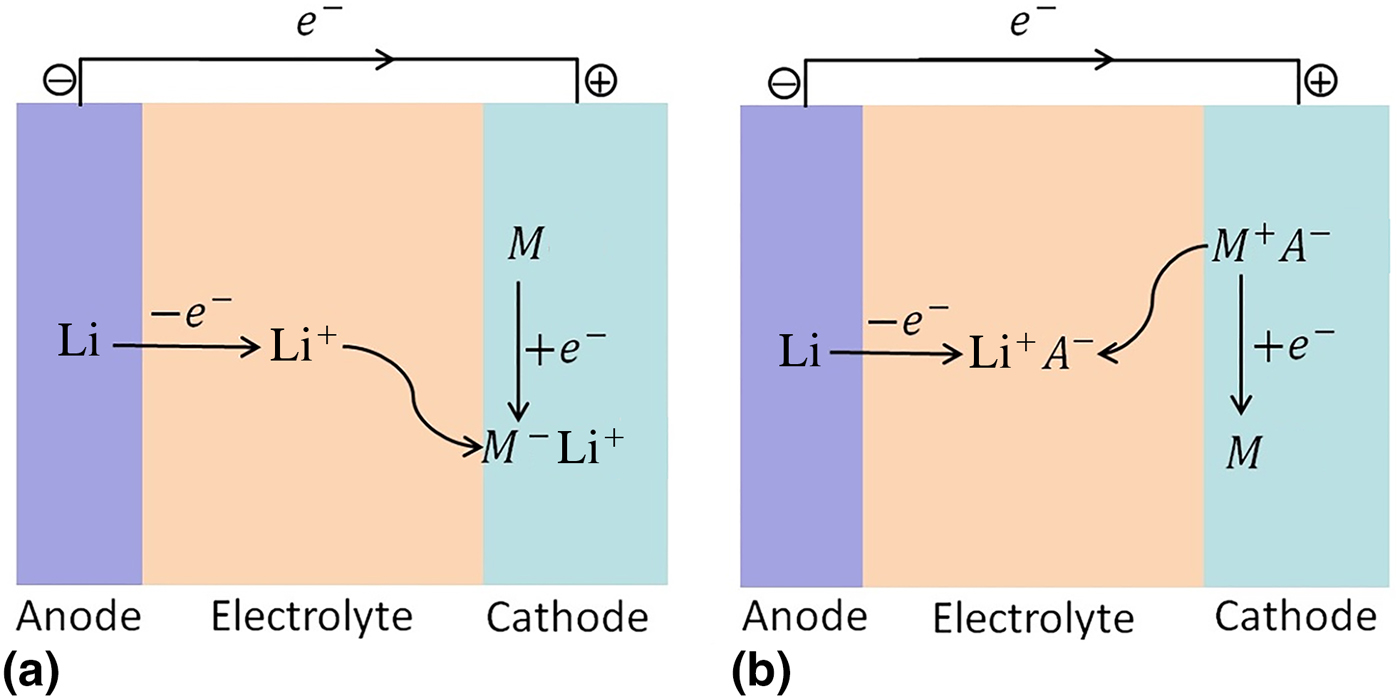
In this Prospective, we review our recent work on doping of organic and inorganic materials for advanced electrochemical batteries and report new results. We focus here on doping by substitution of an atom of a molecular material or inorganic solid by an atom with a different valence. In the literature, sometimes the word “doping” is used to describe charge transfer complexes [Reference Wehling, Novoselov, Morozov, Vdovin, Katsnelson, Geim and Lichtenstein63, Reference Morita, Zakhidov and Yoshino64]; this is not considered here. The main focus here is the effect of doping on the voltage, i.e., on the energetics of interaction of Li, Na, and Mg atoms with the active material. The behavior of the voltage with Li, Na and Mg concentration determines the theoretical capacity. Therefore, doping changes in principle both voltage and capacity; this was explicitly shown for the organic materials considered below.[Reference Lüder, Cheow and Manzhos56] We consider here materials operated by reduction, in which Li, Na and Mg atoms coordinate to or insert into the active electrode material and donate their valence electrons to unoccupied states of the host [Fig. 1(a)]. In the materials considered here, these are in the CB or the LUMO. This mechanism covers all practical inorganic electrode materials and a subset of organic electrode materials. Specifically in the case of organic materials, the oxidation mechanism is often used on the cathode side, in which the active organic electrode material is oxidized in the (battery) charged state and coordinates to anions of the electrolyte and is reduced to neutral state during discharge [Fig. 1(b)][Reference Chen and Manzhos65]; this case is not considered here. This “Prospective” will allow the reader to understand not just the mechanisms by which n- and p-doping affects the voltage but also similarities and differences in the mechanism between organic and inorganic materials. That is to say, we aim to connect the results obtained with different materials and with different types of doping in a coherent picture of doping effects. To this end, the results from previous works reviewed here are also supplemented with new calculations, specifically, to allow for comparison between n- and p-doped materials.
Discharging mechanism in a lithium-ion battery using a Li metal anode and active cathode material M: (a) by reduction, where M− is coordinated to Li+; (b) by oxidation, where M + is coordinated to anions of the lithium salt (A −).

Methods
All calculations reported here were performed using density functional theory (DFT).[Reference Hohenberg and Kohn66–Reference Kohn and Sham67] Different functionals, bases sets, and codes were used which were most suited for a specific system. The reader is referred to the original papers for details.[Reference Chen and Manzhos25, Reference Chen and Manzhos38–Reference Chen, Lüder and Manzhos41, Reference Lüder, Cheow and Manzhos56, Reference Legrain and Manzhos58, Reference Legrain and Manzhos60, Reference Legrain, Malyi and Manzhos61] Here, we only introduce key computed quantities, which are important for a material's performance as an active electrode material and which are significantly influenced by doping. As new computational results are also presented in this “Prospective”, the computational details for those are indicated by referring to corresponding article(s) with the same set-up. The key quantity is the binding energy E b of Li, Na, or Mg atoms to the active material, which can also be called defect formation energy in the case of Li, Na, and Mg insertion into a solid and which is computed as:
 $$E_{\rm b}(n) = \displaystyle{{E(nM - {\rm material}) - E({\rm material}) - nE{\rm (}M{\rm )}} \over n}$$
where M is one of Li, Na, or Mg and n is the number of atoms M. E(nM − material) is the energy of the active material (a molecule, a supercell of a solid, etc.) with n M atoms, E(material) is the energy before the attachment/insertion of M, and E(M) is the energy of one M atom in its aggregate state (bcc Li, bcc Na, and hcp Mg). “material” here refers to doped or undoped molecule or (a supercell of) a solid. Here the binding energy is per one M atom. The binding energy is related to the average voltage for attachment/insertion of n M atoms via[Reference Aydinol, Kohan, Ceder, Cho and Joannopoulos68]
 $$V = - \displaystyle{{E_{\rm b}{\rm (}n{\rm )}} \over {eq}}$$
where e is the elementary charge and q is valence charge, q = 1 for Li and Na, and q = 2 for Mg. The energies in the above are Gibbs free energies; however, they are well approximated by the electronic (internal) energies computed by DFT, as it is done with nearly all ab initio studies of battery materials[Reference Urban, Seo and Ceder69, Reference Zhou, Cococcioni, Marianetti, Morgan and Ceder70] with rare exceptions.[Reference Legrain, Malyi and Manzhos61, Reference Legrain, Malyi, Persson and Manzhos71]
The electronic structure is analyzed using partial densities of states (PDOS) and density difference maps are computed as the difference of electron densities of Li/Na-material complexes and the isolated “material” and the Li/Na atom(s) at the geometries they assume in the complex.
How doping affects electrochemical performance
As argued above, we consider that the doping effect properly speaking is bandstructure modulation. In materials operating by reduction (accepting valence electrons from Li, Na, Mg, etc.) one therefore expects p-doping to lead to lower E b/higher voltage and vice versa. Understanding that other effects than bandstructure modulation will be induced by doping, to what extent does this simplified picture hold? To what extent can E b/voltage be increased or decreased with n- and p-doping? We have analyzed this on a selection of organic and inorganic materials corresponding to some of the major classes of practically used or actively researched active electrode materials.
Organic materials
p-Doping
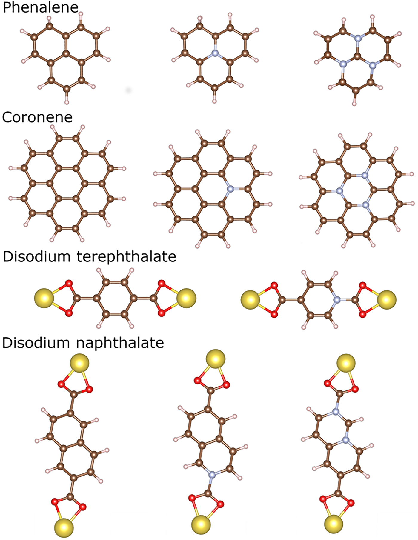
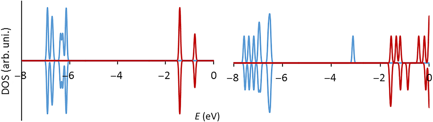
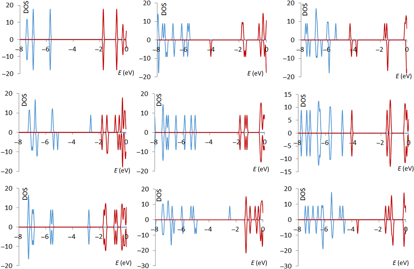
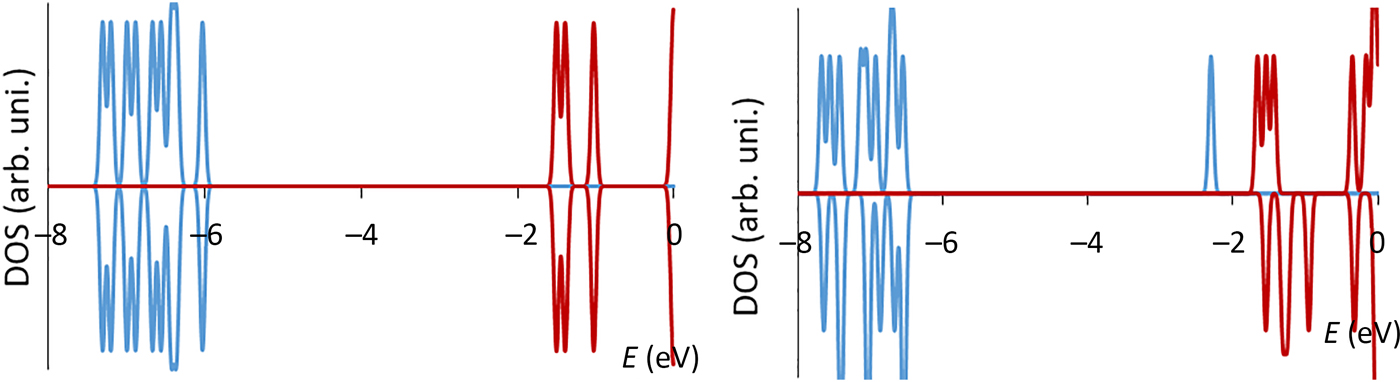
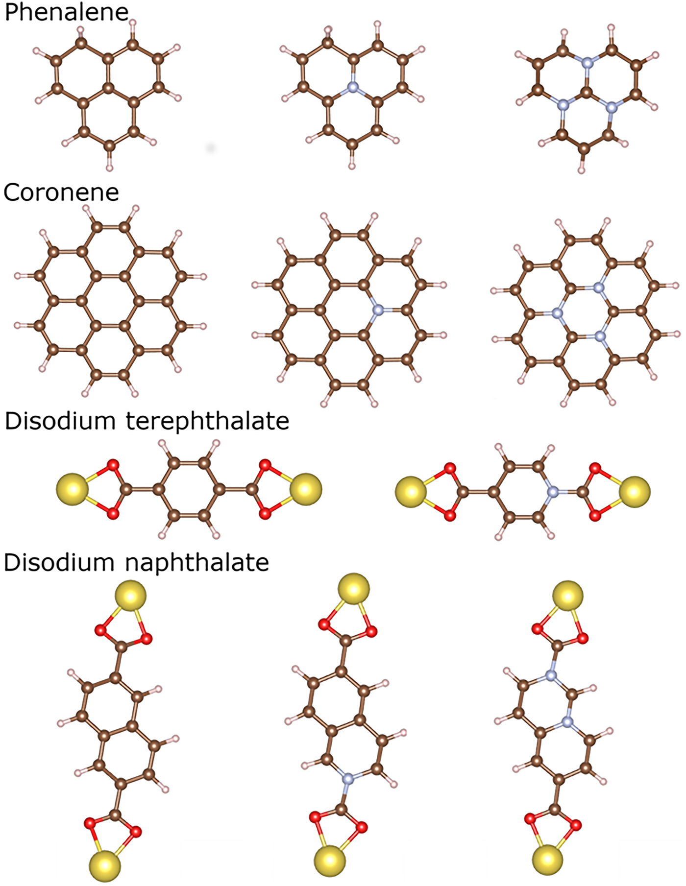
In Ref. Reference Lüder, Cheow and Manzhos56, we considered doping of several prototypical molecules with potential to be used as electrode materials of organic batteries. This included graphene flakes of different sizes and sodium salts of dicarboxylic acids with aromatic cores of different sizes (benzene and naphthalene). These molecules feature functional blocks that have attracted much interest in research on organic batteries.[Reference Rodriguez-Perez, Jian, Waldenmaier, Palmisano, Chandrabose, Wang, Lerner, Carter and Ji72–Reference Armand, Grugeon, Vezin, Laruelle, Ribière, Poizot and Tarascon75] These molecules are shown in Fig. 2. We compared Li and Na attachment properties of these molecules and of their p-doped versions, which are also shown in Fig. 2. The dopant used was boron replacing a carbon atom that is not bound to a hydrogen atom, effectively creating a “hole” state in molecules. In all of these molecules, the attachment of a Na (or Li) atom leads to the donation of alkali atom's valence electron to a LUMO-like state of the molecule. This is illustrated in Fig. 3 for the case of disodium terephthalate (Na2Tph), which shows densities of states before and after the attachment of Na atoms (the DOS are computed with the same level of theory as in Ref. Reference Lüder, Cheow and Manzhos56). The attachment of one Na creates a singly occupied molecular orbital (SOMO), which is derived from the LUMO of the bare molecule and which is stabilized by occupation (spin-polarized state in the gap in Fig. 3, right panel). The energy of this SOMO directly contributes to E b and therefore voltage via the band energy. This is the same for all the considered molecules, e.g., in the left panels of Fig. 4, this behavior of the electronic structure is shown for coronene. The attachment of a second Na creates a doubly occupied orbital derived from the LUMO, and the attachment of subsequent Na atoms fills in higher-energy orbitals (some of which may be Na-centered; see Ref. Reference Chen and Manzhos38).
Top row: phenalene and its single and triple doped versions. Second row: coronene and its single and triple doped versions. Third row: disodium terephthalate and its doped version. Last row: disodium naphthalene dicarboxylate and its single and double doped versions. Atom color scheme: C—brown, O—red, Na—yellow, H—pink, with the dopant atom shown in blue.
Densities of states of disodium terephthalate before (left) and after (right) Na attachment. Spin channels are shown as positive and negative values. Occupied states are plotted in blue and unoccupied in crimson.

From left to right: density of state (DOS) of coronene, single p-doped coronene and triple p-doped coronene. From top to bottom: DOS of pristine systems, with one and with two Na atoms attached. Occupied states are shown in blue and unoccupied ones in crimson.

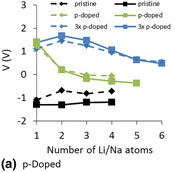
p-Doping of these molecules creates unoccupied states in the HOMO–LUMO gap; the number of such states equals to the number of holes created by the dopants, for example, one state is created by a single three-valent dopant and three states by three such dopants, as shown in Fig. 4 (second and third columns). These states accept valence electrons from attached alkali atoms and become further stabilized by occupation, as it is shown in Fig. 4 for the case of 1 and 2 Na attachment to doped coronene (second and third rows). For single p-doping, the first attached Na atom donates an electron to the hole and the second Na atom donates an electron to a LUMO-like orbital; in the case of triple p-doping, the valence electrons of both attached Na atoms are accommodated in the hole states. Because the energy of these states is much lower than that of the LUMO, E b is significantly strengthened for the attachment of a number of alkali atoms equal to or less than the number of introduced holes, eventually leading to a higher voltage and potentially to larger capacities. The increase in voltage is illustrated in Fig. 5, where estimated voltages for lithium and sodium attachment to coronene and doped coronene are shown. In Fig. 5 (as well as in section “Inorganic materials” below) some curves have upward sloping regions. Those upward sloping regions indicate expected segregation to the maximum of the slope [Reference Sk and Manzhos18, Reference Chen, Lüder and Manzhos41]; for example, the formally computed voltage for triple p-doped case, which is higher for 2 than for 1 Li attachment, implies phase segregation into areas of doubly lithiated and non-lithiated molecules, at a voltage of about 1.7 V.
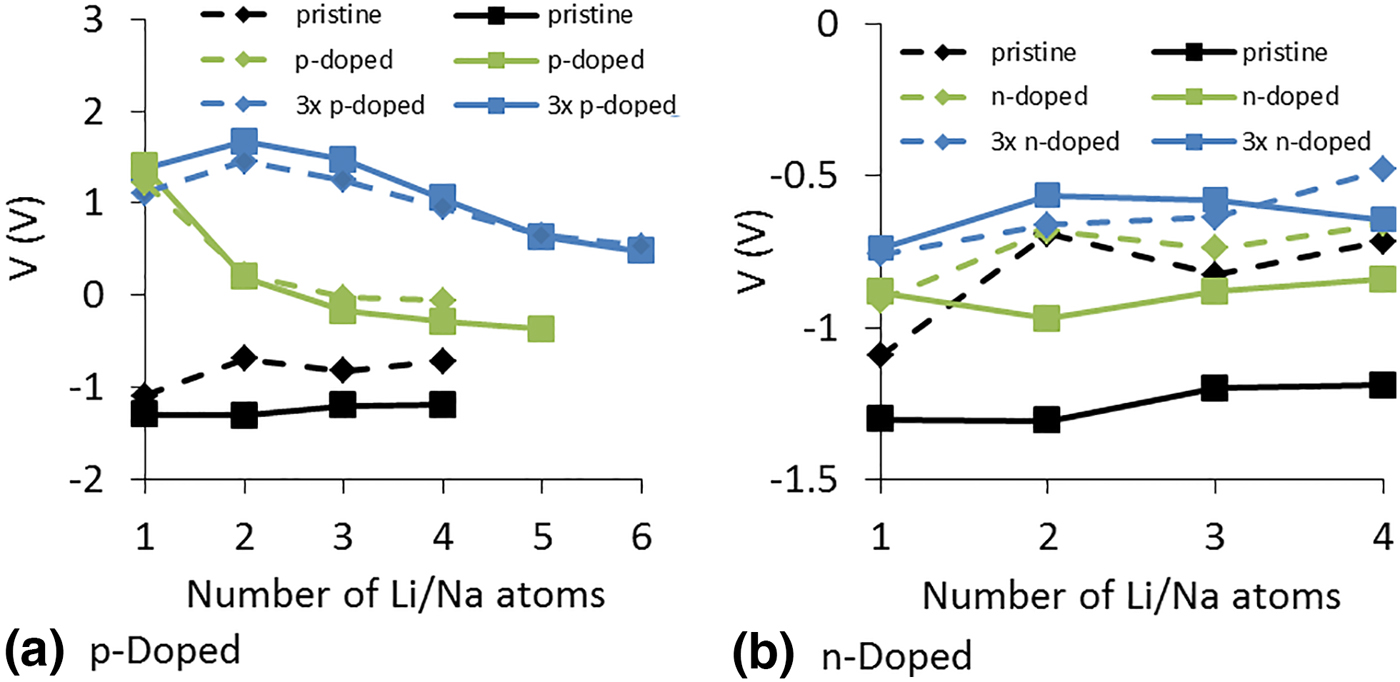
Calculated voltages for lithiation (solid lines) and sodiation (dashed lines) of pristine coronene (black lines) and its doped forms, i.e., with one (green) and three (blue) p- and n-dopants in (a) and (b), respectively.
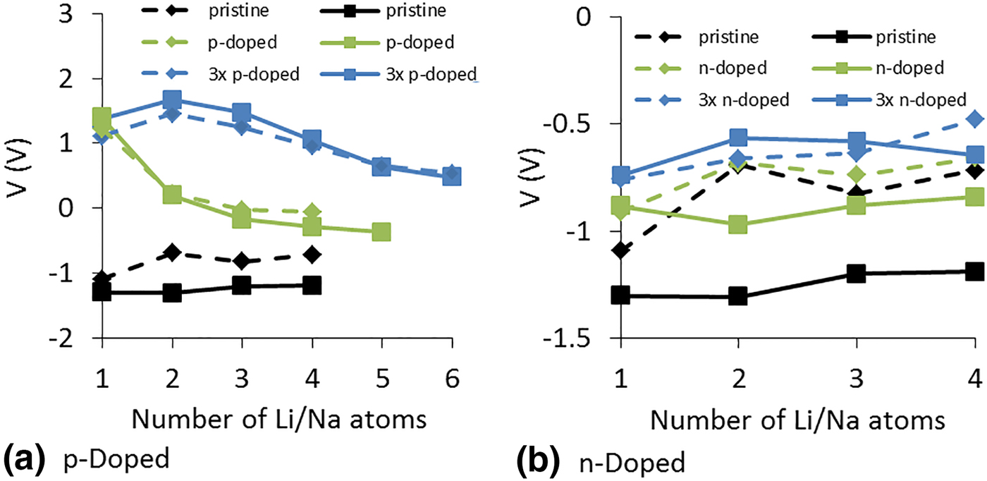
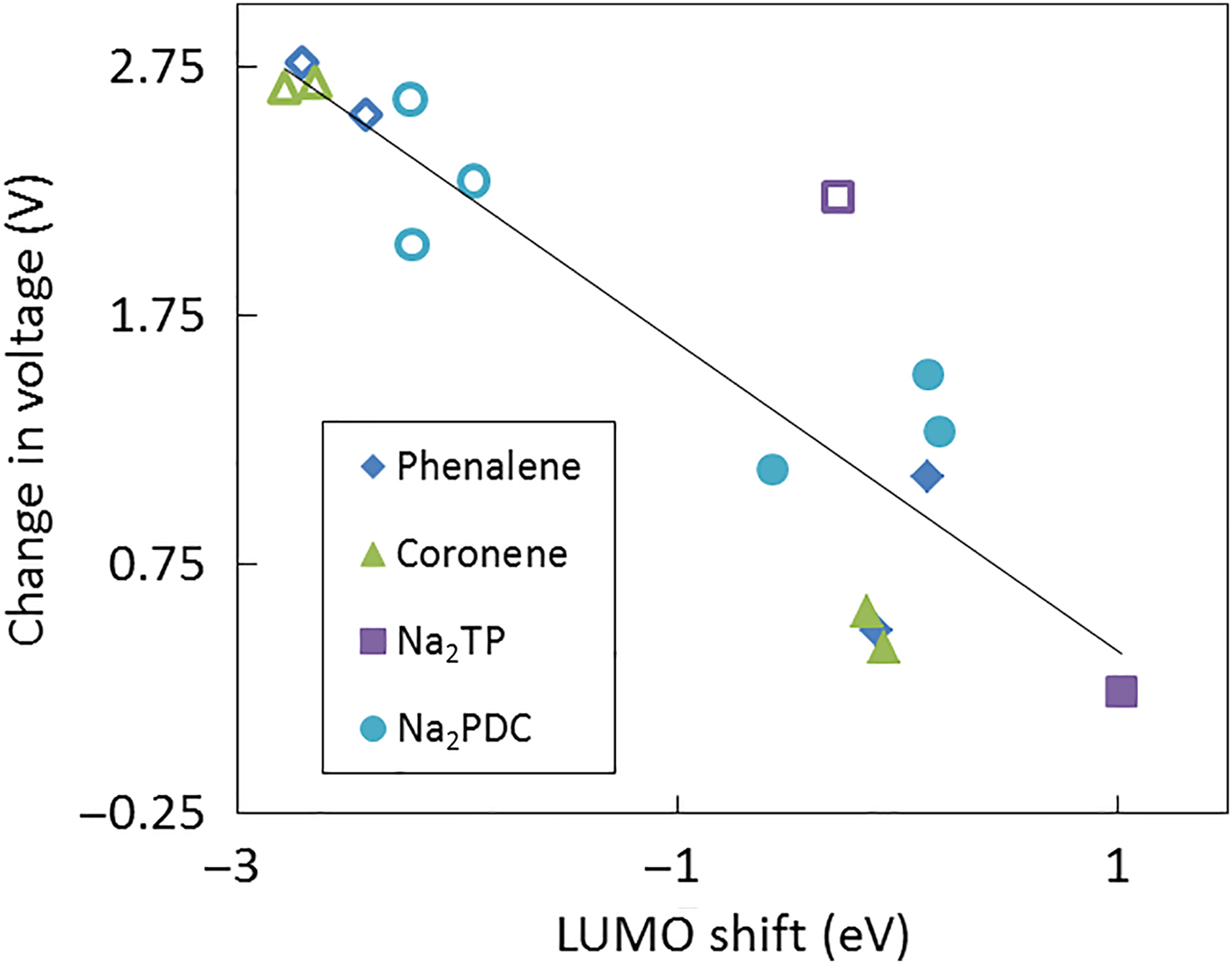
Figure 5(a) clearly confirms the correlation of the voltage with the bandstructure, in that single p-doping (green curve) significantly increases the voltage (V) for first Li/Na attachment with much smaller effects on the rest of the lithiation/sodiation curve while triple p-doping significantly lifts V for several Li/Na attachments (blue curves). That voltage is also noticeably increased for the attachment of further Li/Na beyond the number of introduced holes. This can be explained by the effects of strain (see below). Overall, p-doping can be used to increase the voltage of organic electrodes by about 3 V and can be used to either induce electrochemical activity of materials that do not possess it (i.e., to move V above 0) or to design organic cathodes operated by reduction. While p-doping increased V here for Li and Na attachment, we did not observe this approach to benefit Mg attachment, which results in very weak binding energies for the here presented molecules. Note that Fig. 5 is obtained from calculations in vacuum and ignores effects of aggregate states, which can be significant [Reference Chen and Manzhos38, Reference Chen and Manzhos39]; it, however, reliably represents the doping effect. With p-doping, the doping, i.e., bandstructure, effect dominates the overall influence on the voltage, as is also illustrated in Fig. 6, where changes in LUMO are related to changes in V.
LUMO shifts (in eV) versus change in voltages due to doping for the attachment of one Li atom onto coronene (green), phenalene (blue), disodium terephthalate (Na2TP) (purple) and disodium naphthalate (Na2PDC) (light blue). The empty (filled) markers show the data points for p-doping (n-doping). The black line obtained by linear regression shows the trend of change in voltage due to shift in LUMO energy.

n-Doping
We have seen above that p-doping strengthens E b through electronic structure effects. What would be the effect of n-doping? n-Doping is used with active battery materials and is sometimes claimed to result not only in improved electronic conductance and thereby improved rate performance—which is intuitive—but also in a higher voltage, which is not intuitive.[Reference Huang, Wu, Dianat, Bobeth, Huang, Mai, Zhang, Cuniberti and Feng62] Indeed, the above electronic structure based argument suggests that n-doping could weaken E b and decrease voltage, as fewer low-lying empty states become available to accept electrons from Li/Na. For example, Fig. 7 (top row) shows the DOS of single and triple n-doped coronene, to compare with Fig. 4 (top row).
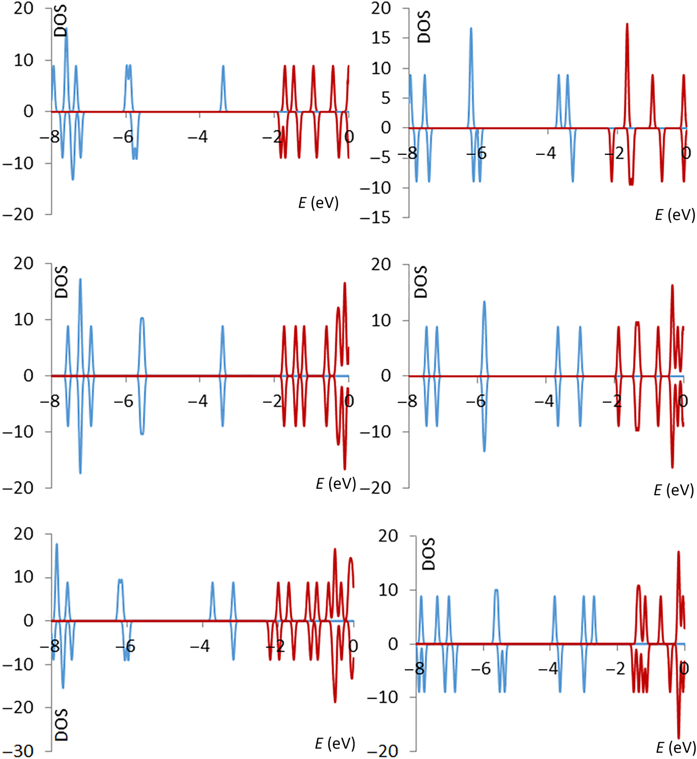
From left to right: density of state (DOS) of single n-doped coronene and triple n-doped coronene. From top to bottom: DOS of pristine systems, with one and with two Na atoms attached. Occupied states are shown in blue and unoccupied ones in red.

Here, a single n-dopant introduces an occupied state in the gap which is LUMO-derived, the new SOMO. The LUMO-derived unoccupied, SUMO component is at a similar energy as the original LUMO. When one Li or Na atom is attached, the SUMO becomes a newly occupied state, which is stabilized. This process creates a doubly occupied state in the gap. A second Li/Na attachment leads to occupation of higher-lying states. Triple n-doping creates respectively three occupied states in the gap and the attachment of Li/Na atoms leads to occupancy of, and it can stabilize higher-energy states, as illustrated in Fig. 7. Electronic state energetics of Fig. 7 suggest almost no strengthening of E b (as SUMO is almost at the energy as the LUMO of coronene) for single n-doped coronene and only a slight decrease (strengthening) in the binding energy for triple n-doped coronene (as the SUMO is slightly lower than the LUMO of coronene). Therefore, the voltages of single and triple n-doped coronene are expected to be similar or slightly larger than those of their pristine version, from the bandstructure perspective. The reorganization of the electronic states due to n-doping is important for application of materials as electrodes since occupied and unoccupied states shift to lower energies in contrast to a “frozen state” picture, which only considers changes in occupancy. While the electronic relaxation is somewhat intuitive, it also points out that electronic structure calculations are required to obtained qualitative and quantitative insights into the electronic effects (and also structural effects) of n-doping in materials.
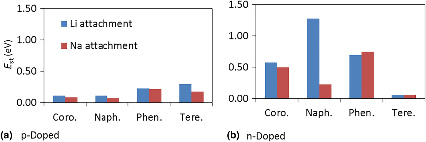
Computed voltages for n-doped coronene are shown in Fig. 5(b). They show a slightly higher voltage versus the non-doped case. The extent of the change in V in depends on the type of alkali atom, here Li or Na. Interestingly, with an increase of the number of dopants in the system, the voltage also increases. In the n-doping case, the electronic structure effect on E b, i.e., doping effect properly speaking, is not the determining factor of changes in voltage. For coronene and other molecules, this is also seen in a much weaker correlation between voltage and LUMO for the case of n-doping compared with p-doping, as shown in Fig. 6. The dominant influence on the voltage is affected here by the strain effect, i.e., destabilization of molecular structure by doping makes the molecule more reactive and thereby strengthens E b. This is illustrated in Fig. 8, which shows strain energy due to Li/Na attachment with and without doping estimated as deformation energy of the molecule due to Li/Na attachment for two graphene flakes (coronene and phenalene) and two aromatic carboxyl molecules (disodium terephthalate and disodium naphthalate). Overall, the contributions to the binding energy by strain effects caused by Li/Na atom attachment are smaller for p-doping than for n-doping and Li attachment causes larger strain energies than Na attachment.
Average strain energies (E st) for the attachment of one lithium or sodium atom onto pristine and doped coronene (coro), phenalene (phen), disodium terephthalate (tere), and disodium naphthalate (naph). p-Doping is shown in (a) and n-doping in (b).

Contrary to p-doping, therefore, with n-doping, the bandstructure effect on binding energy and voltage is muted. That is why n-doping can still be used to increase the voltage but such an increase is destined to be small (compared with E b changes in excess of 3 eV that can be obtained with p-doping). n-Doping has, however, the advantage of increasing the electronic conductance due to a smaller gap (as is easily observed in Fig. 7), which is beneficial for rate performance of a battery.
Interplay between p- and n-doping
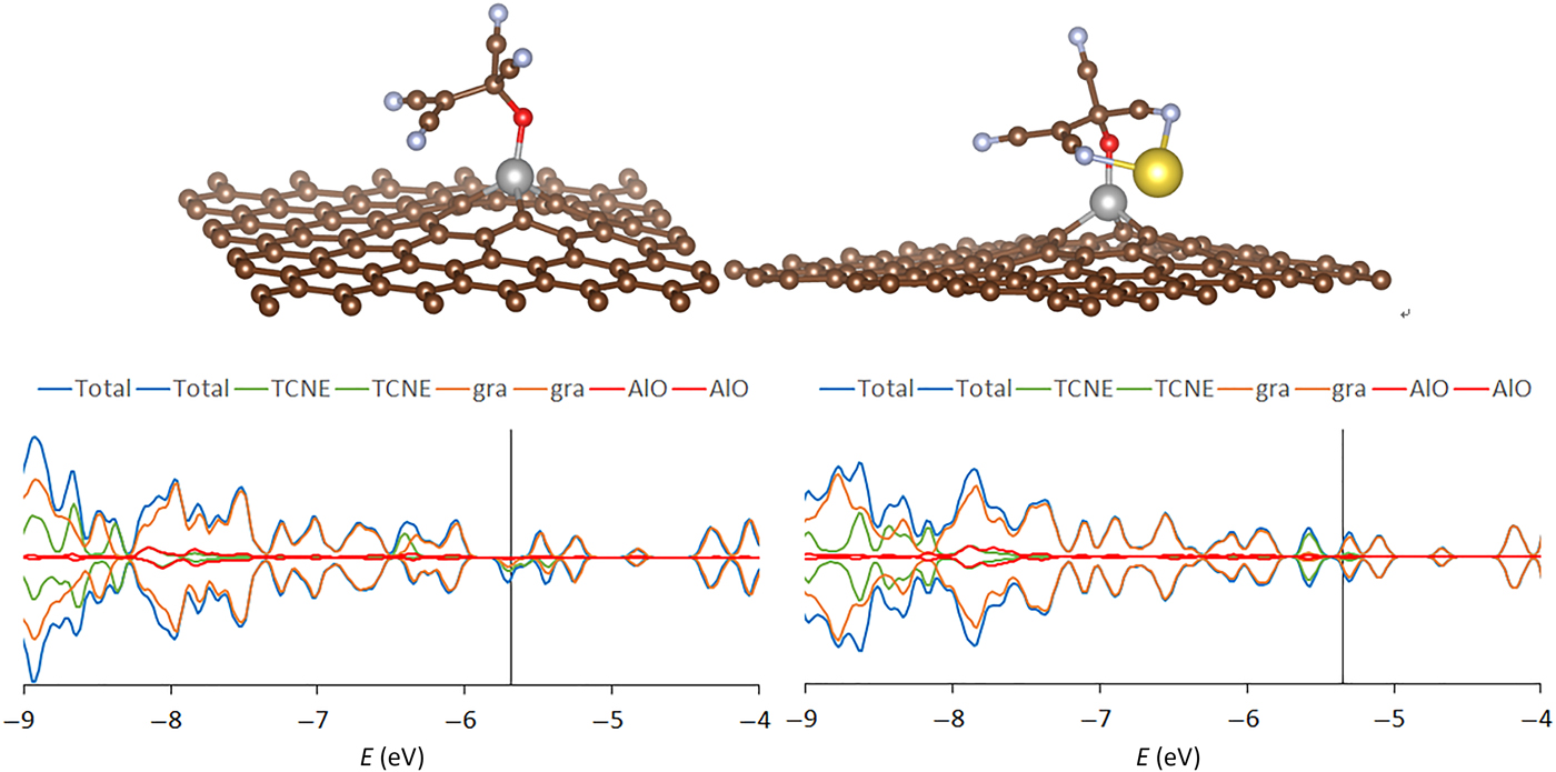
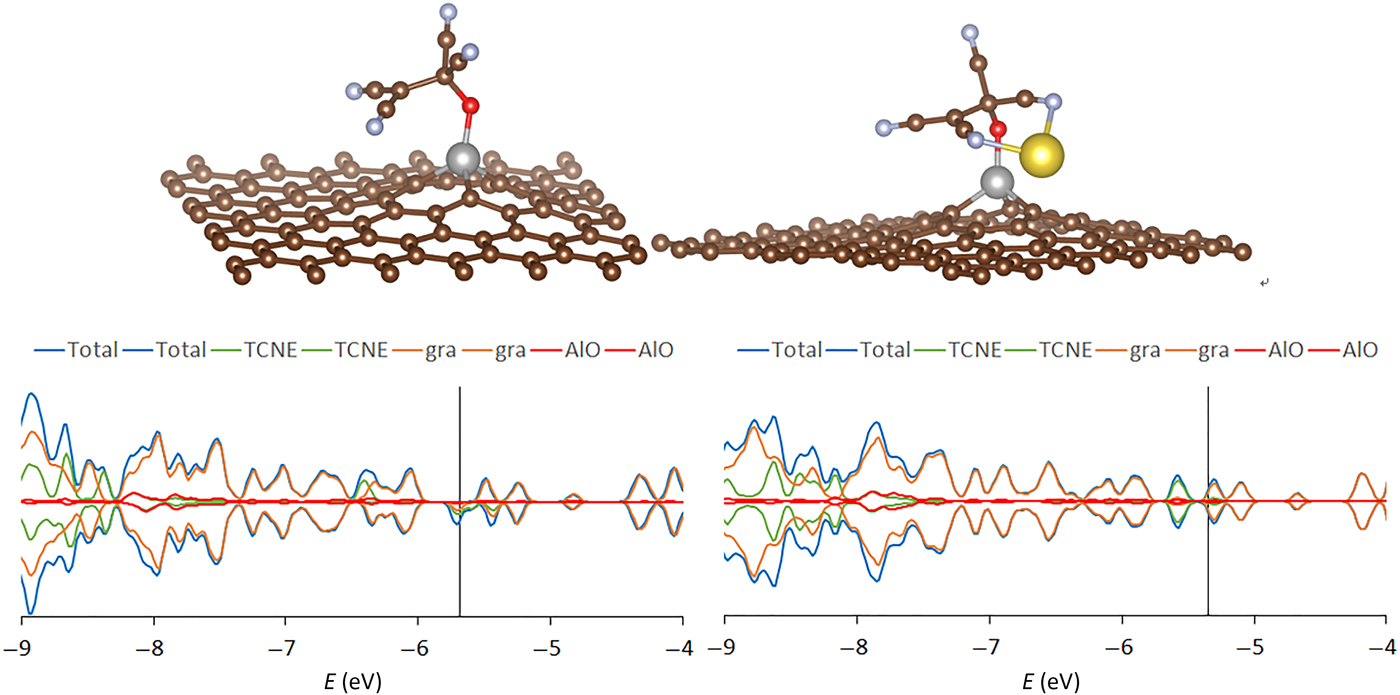
In Refs. Reference Chen and Manzhos25, Reference Chen and Manzhos38–Reference Chen and Manzhos40, we suggested that TCNE may be a good organic electrode material for high rate Li and Na ion batteries. Specifically, based on the fact that it can provide E b values for both Li and Na attachment corresponding to voltages just exceeding the reduction potential of common organic electrolytes, TCNE could be an effective high-rate organic anode. Moreover, it can potentially attach multiple Li or Na atoms before the potential approaches zero (one Li or one Na atom attachment per TCNE molecule corresponds to a theoretical capacity of about 210 mAh/g). As a way to immobilize TCNE, we proposed a chemisorbed configuration on Al-doped graphene in which TCNE binds to the Al substitutional via an O atom[Reference Chen and Manzhos25] as shown in Fig. 9. Substitutional Al plays the role of a p-dopant in graphene. This is also true for the O–Al–graphene system used in Ref. Reference Chen and Manzhos25. On the other hand, the (computed) LUMO of TCNE is lower in energy than the (computed) VBM of graphene, and TCNE is negatively charged. That is, TCNE plays the role of a surface p-dopant.[Reference Chakrapani76] The result is a system where TCNE is n-doped, graphene is p-doped, and the overall system is p-doped. This can be seen from the PDOS also shown in Fig. 9. In the TCNE–O–Al–graphene complex, the Fermi level at about −5.5 eV is at the SOMO of TCNE, which corresponds to the LUMO of a free molecule; this is n-doping. On the other hand, the graphene–Al–O system corresponds to a p-doped graphene sheet in which the p-dopant is Al–O as it creates empty states in graphene. Interestingly, the hole states in graphene are shifted with respect to the TCNE–Al–O–graphene as the TCNE molecule causes electron depletion from the graphene-Al–O subsystem. This system shows a higher computed voltage and a higher theoretical capacity than free TCNE, similar to the effect of p-doping described in section on p-doping in organic materials. Indeed, we showed that upon successive Li or Na attachment, the charge is accommodated by the substrate; see Figs. 7 and 8 of Ref. Reference Chen and Manzhos25.
Top: the TCNE–O–Al–graphene complex before (left) and after (right) sodium attachment. Atom color scheme: C—brown, O—red, Na—yellow, N—blue, Al—gray. Bottom: partial density of states of TCNE–O–Al–graphene complex before (left) and after (right) sodium attachment. The vertical lines mark the Fermi level. The upper left panel is reproduced with permission from Ref. Reference Chen and Manzhos25. Copyright by AIP Publishing, 2015.
For TCNE immobilized on graphene, the situation with n-doping is different. With the same level of theory as was used for TCNE–O–Al–graphene,[Reference Chen and Manzhos25] we have computed an equivalent n-doped system with a substitutional N atom instead of Al (doping graphene with a N atom is frequently applied[Reference Huang, Wu, Dianat, Bobeth, Huang, Mai, Zhang, Cuniberti and Feng62, Reference Reddy, Srivastava, Gowda, Gullapalli, Dubey and Ajayan77]). Previously it was shown that n-doping enhances the performance of graphene as electrode material, in particular in terms of reversible discharge capacity attributed to surface defect states.[Reference Reddy, Srivastava, Gowda, Gullapalli, Dubey and Ajayan77] However, we could not achieve a chemisorbed configuration for TCNE in this way, i.e., TCNE would not immobilize on (form a bond with) the graphene–N–O complex.
“Pseudo” doping
In some practically useful cases, substitution with an atom of lower/higher valence does not amount to substitutional doping. An example is disodium pyridine dicarboxylate (Na2PDC), which is a related material to disodium terephthalate (Na2Tph) considered above. Na2PDC can be used as anode material in Na ion batteries just like Na2Tph has been.[Reference Park, Shin, Woo, Choi, Shin, Oh, Lee and Hong17, Reference Sk and Manzhos18, Reference Chen, Lüder and Manzhos41] The two molecules differ in that Na2PDC can be obtained by replacing a –CH-group on the aromatic ring with a N atom, see Fig. 10. Note that contrary to n-doping considered above, here, the number of valence electrons does not change. This is reflected in the DOS with symmetric spin channels like in the Na2Tph molecule, see Fig. 11 (compare with Fig. 3). The band gap is however, somewhat lower than in Na2Tph: it is 4.5 eV in Na2PDC versus 4.7 eV in Na2Tph (B3LYP values). This is believed to lead to somewhat higher electronic conductance and rate capability of the electrode[Reference Chen, Lüder and Manzhos41] and improved rate capability was in fact confirmed in an experiment.[Reference Padhy, Chen, Lüder, Reddy, Manzhos and Balaya78] But this substitution is not a doping effect; no states are created in the gap, and Na attachment proceeds by filling LUMO-derived spin states, similarly to the case of (undoped) Na2Tph; see Fig. 11. Interestingly, Na attachment results in a stronger binding energy than in the case of Na2Tph. However, this is not due to the strain effect, which we observed for pure substitutional n-doping; instead, the stronger binding is a consequence of bond formation between the attached Na and both the N and an O atom, as is evidenced by the charge density difference map for a single molecule shown in Fig. 10. This is in contrast to Na attachment to Na2Tph in which the Na atom binds only to oxygen (Fig. 10). This stronger binding to the pyridine part of the molecule is expected to lead to a higher voltage as predicted in a theoretical study[Reference Chen, Lüder and Manzhos41] and recently also reported experimentally.[Reference Padhy, Chen, Lüder, Reddy, Manzhos and Balaya78] Moreover, the computed voltage profile has two plateaus indicating that the discharge undergoes two separate Na attachment mechanisms.[Reference Chen, Lüder and Manzhos41, Reference Padhy, Chen, Lüder, Reddy, Manzhos and Balaya78] In the initial discharge phase, the Na atoms attach to the molecule close to one of the carboxyl groups and the “doped” site (corresponding to the first plateau); when all those sites have been occupied, the attachment takes place on the opposite site of the molecule at the other carboxyl group (corresponding to the second plateau) that has a weaker bond strength.[Reference Chen, Lüder and Manzhos41, Reference Padhy, Chen, Lüder, Reddy, Manzhos and Balaya78] The “pseudo” doping has a noticeable effect on the voltage profile and therefore on the performance of electrode materials while it cannot be strictly addressed as doping.
The structures of a disodium terephthalate (left) and a disodium pyridine dicarboxylate (Na2PDC) (middle) molecules with a Na atom attached to them. Atom color scheme: C—brown, O—red, N—blue, Na—yellow, H—pink, with the attached Na atom shown in turquoise. Right: charge density difference plot for the attachment of Na to Na2PDC with light turquoise showing charge depletion and light yellow charge accumulation regions. Bonds between the attached Na atom and molecule's N and O atoms are seen as accumulated density.

Density of states of disodium pyridine dicarboxylate (Na2PDC) before (left) and after (right) Na attachment. Spin channels are shown as positive and negative values. Occupied states are plotted in blue and unoccupied in red.

Inorganic materials
Explicit substitutional doping in Si and Ge
In Refs. Reference Legrain and Manzhos58 and Reference Legrain and Manzhos60, we explored p-doping as a strategy to improve the insertion energies of Li, Na, and Mg in group IV monoelemental semiconductors silicon and germanium. Silicon has attracted significant attention as a high capacity anode material for Li ion batteries.[Reference Zhang, Hu, Chen, Guo, Liu, Xu, Zhong, Cheng, Wu, Meng, Huang, Dou and Liu79, Reference Li, Xu, Li, Yin, Wan and Guo80] Germanium has the advantage over Si of a higher alkali atom diffusivity and higher electronic conductivity; specifically, Na diffusion rate is prohibitively low in Si, while it is not in Ge.[Reference Baggetto, Keum, Browning and Veith81, Reference Malyi, Tan and Manzhos82] However, the thermodynamics of Na insertion is unfavorable in both Si and Ge. Si is well known to be electrochemically inactive for Na,[Reference Ge, Rong, Fang and Zhou13, Reference Komaba, Matsuura, Ishikawa, Yabuuchi, Murata and Kuze14] while somewhat contradictory results were reported for Ge; while it is generally thermodynamically unfavorable, sodiation of Ge has been achieved by pre-activation by Li cycling, likely due to a combined effect of amorphization and microstructure.[Reference Kohandehghan, Cui, Kupsta, Ding, Lotfabad, Kalisvaart and Mitlin83] Interestingly, Li insertion into pure Si is also thermodynamically unfavored, with defect formation energies for Li insertion into the lowest-energy tetrahedral site that are about 0.3 eV above the cohesive energy of Li.[Reference Legrain and Manzhos58, Reference Zhang, Hu, Chen, Guo, Liu, Xu, Zhong, Cheng, Wu, Meng, Huang, Dou and Liu79, Reference Legrain, Malyi and Manzhos84] It is now understood that the effective lithiation of silicon proceeds by a front propagation rather than by single atom insertion and diffusion.[Reference McDowell, Lee, Nix and Cui85, Reference Liu, Zhang, Zhong, Liu, Zheng, Wang, Cho, Dayeh, Picraux, Sullivan, Mao, Ye and Huang86] It is desirable to improve insertion energetics of both Na and Li in Si and Ge, in the first case (Si) to enable Na storage, in the second (Ge) to enable a different mechanism. Mg insertion is strongly unfavored in both Si and Ge, even though the final state of charge Mg2Si is thermodynamically favored. A similar situation exists for magnesiation of Sn and even led to speculation about possible use of Sn as anode for Mg ion batteries, based on the favorable formation energy of Mg2Sn.[Reference Legrain, Malyi, Persson and Manzhos71, Reference Jin, Li, Wang and Fu87–Reference Singh, Arthur, Ling, Matsui and Mizuno90] It would therefore also be desirable to improve the energetics of Mg insertion in group IV semiconductors.
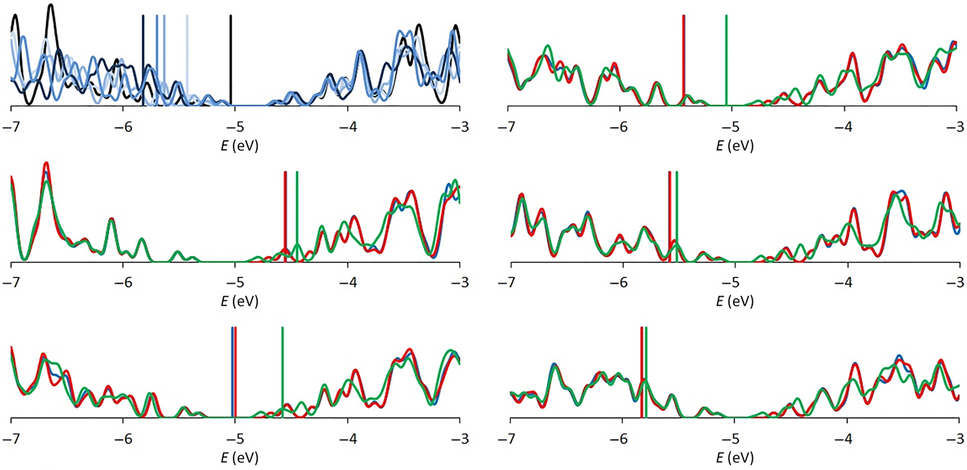
We applied the strategy of p-doping, i.e., creation of holes at the top of the VB and effectively lowering the lowest unoccupied states of the host material, which would accept the valence electrons from the inserted Li/Na/Mg atoms. Li and Na atoms prefer to insert at interstitial sites and they donate their valence electrons to the CB of the host.[Reference Legrain and Manzhos58, Reference Legrain and Manzhos60, Reference Malyi, Tan and Manzhos82] Mg atoms prefer substitutional sites in Ge[Reference Legrain and Manzhos60] but interstitial sites in Si (by a small margin, according to our calculations[Reference Legrain and Manzhos58]). p-Doping is therefore expected to enhance the binding energy as lower-energy electronic states in the frontier region of the VB would be occupied instead of states in the CB. Indeed, we found that Al doping of Si strongly enhances the insertion energies. The tri-valent Al atoms occupy substitutional sites[Reference Legrain and Manzhos58] and act as p-dopants. The doping effect is clearly seen in the PDOS plots shown in Fig. 12: Al doping creates empty states in the frontier states of the VB as the Fermi level shifts to lower energies with increasing dopant concentration. Upon insertion of Li/Na/Mg atoms, their valence electrons fill those states. This is also confirmed by comparing the PDOS with monovalent Li, Na and bivalent Mg: in pure Si, valence electrons of all Li, Na, and Mg are donated into the conduction band, as expected. With a single p-dopant, one donated electron is accommodated in the valence band, meaning that in the case of single Mg insertion, 1 electron remains in the CB. As more empty states are created with more Al atoms, more electrons are accommodated in the VB. As a result, there is strengthening of the binding.
Top left panel: density of states and Fermi levels of pure (black) and Al-doped Si (1 Al—very light blue, 2 Al—light blue, 4 Al—blue, 8 Al—dark blue). Top down and left to right: density of states and Fermi levels (in eV) of the pure and Al-doped Si, for 0, 1, 2, 4, and 8 Al atoms, respectively, in the Si cell when one atom of Li (blue), Na (red) or Mg (green) is inserted.

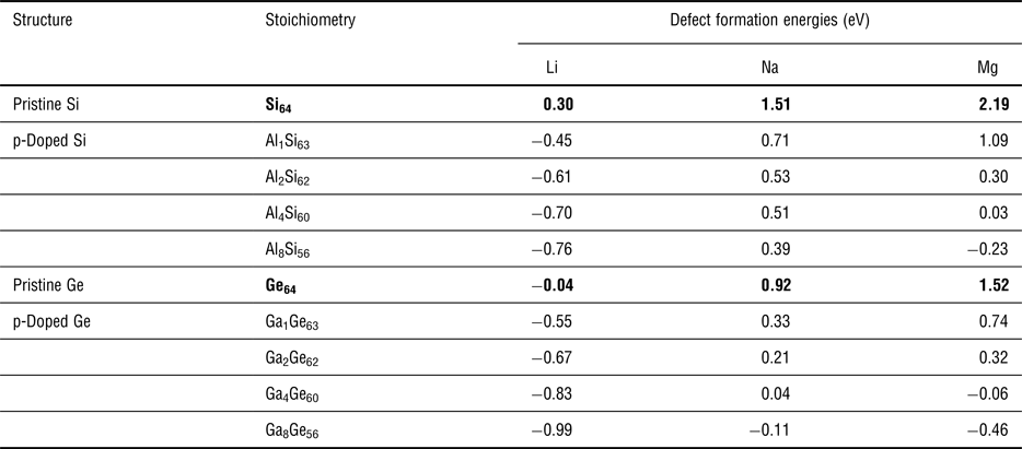
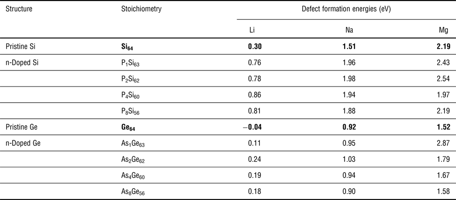
Table I shows how the insertion energy (versus the cohesive energy of respectively Li, Na, and Mg) changes with dopant concentration: for Li and Na insertion, the first p-dopant has the strongest stabilizing effect of about 0.8 eV. More p-dopants marginally enhance E b. This correlates well with the DOS changes caused by Al doping, whereby the first Al makes the valence electron of Li or Na go to a much lower energy state (form CB to VB) while subsequent Al atoms create slightly lower lying states in the VB, see Fig. 12. In the case of interstitial Mg, two Al atoms are needed to create two states in the VB to accommodate the two valence electrons of Mg; therefore, the first two Al atoms have a strong effect, the first strengthening E b by about 1 eV and the second by another 0.8 eV, with subsequent Al atoms having a much smaller effect. Higher dopant concentrations are helpful to enhance E b with the insertion of multiple Li/Na/Mg atoms, as expected, see Fig. 2 of Ref. Reference Legrain and Manzhos58.
Effect of p-doping on the lowest insertion energies (in eV) versus bulk metal reference states for the insertion of one atom of Li, Na, and Mg at different Al concentrations in bulk Si[Reference Legrain and Manzhos58] and at different Ga concentrations in Ge.

Values for the pristine systems (bold) are given as reference.
With the same level of theory as given in Ref. Reference Legrain and Manzhos58, here we also compute the electronic structure of n-doped silicon and the insertion energies for Li/Na/Mg into n-doped silicon. The n-dopant used here is phosphorus (P). The doped structures are similar to those of the p-doped Si, but with P atom(s) replacing Al atom(s), see Fig. 1 in Ref. Reference Legrain and Manzhos58. In Ref. Reference Legrain and Manzhos58 (i.e., the p-doping case), the k-point mesh was chosen to converge the energies leading to converged theoretical voltages. As here we are focused specifically on the effects of doping on the DOS, we also use a denser k-point sampling (9 × 9 × 9) to resolve fine details in the electronic structure of n-doped Si. This provides a clearer understanding from the electronic structure perspective.
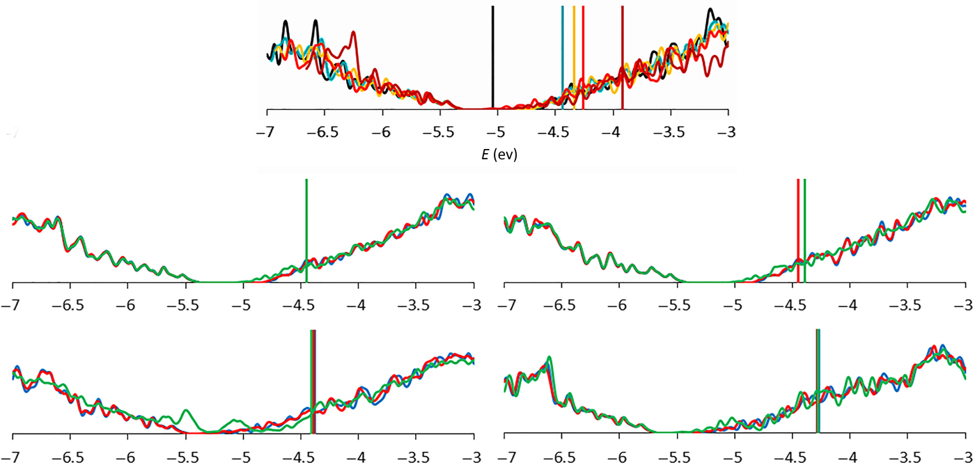
Our new n-doping results provide a comparison of the effects of n- and p-doping in silicon. The computed DOSs for the n-doped cases are shown in Fig. 13. The shift of the Fermi levels relative to the band gap is as expected for the n-doped material as the Fermi level moves to higher energies indicating the occupation of states that are unoccupied in the pristine material. Moreover, the Fermi level shifts more with the increase of the number of n-dopants, but also the effects of reorganization of states becomes more noticeable in the DOSs. Also, distortions in the crystal structure are more significant with more dopant atoms.
Top left panel: density of states and Fermi levels of pure (black) and p-doped Si (1 P—cyan, 2 P—orange, 4 P—red, 8 P—dark red). Top down and left to right: density of states and Fermi levels (in eV) of the pure and p-doped Si, for 1, 2, 4, and 8 P atoms, respectively, in the Si cell when one atom of Li (blue), Na (red), or Mg (green) is inserted.

The DOS shows typical features of n-doping when Li/Na/Mg are inserted into the n-doped Si structures. In particular, the bottom of the CB of pristine Si is occupied and the Fermi level shifts deeper into the CB with more dopants. A peculiar case is Mg insertion into P4Si60. Its DOS shows signs of defect formation with a strong increase of state density around −5.5 and −5.0 eV; this is caused by a large structural change (displacement of some Si atoms). The computed insertion energies for the insertion of Li/Na/Mg are in agreement with simple theoretical assumptions. In particular, the newly occupied state due to the n-dopant would require that the electron of the inserted Li/Na/Mg atom occupy a higher energy state. Therefore, the binding strength would be weakened compared with the undoped case. This can be seen in Table II: lithiation is weakened by about 0.5 eV, sodiation by about 0.4 eV and magnesiation by about 0.2 eV, somewhat depending on the number of n-dopants.
Effect of n-doping on the lowest insertion energies (in eV) versus bulk metal reference states for the insertion of one atom of Li, Na, and Mg at different P concentrations in bulk Si and at different As concentrations in Ge.

Values for the pristine systems (bold) are given as reference.
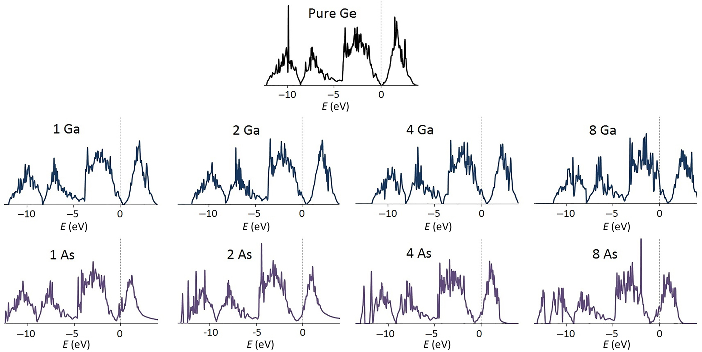
Similar to the case of Si, p-doping of Ge with a group III element—Ga in this case—strongly enhances insertion energetics.[Reference Legrain and Manzhos60] The mechanism is the same, whereby Ga atoms create unoccupied states in the VB that can accommodate valence electrons of Li, Na, and Mg (p-doping). This is illustrated in Fig. 14, which shows changes in DOS upon addition of different concentrations of Ga in Ge. The opposite effect is expected for n-doped Ge that is an occupied state is created in the conduction band. We therefore provide here new results based on the same level of theory for As doped Ge. Figure 14 also shows the effects of n-doping (with As) on the DOS of Ge. The DOS of p(n)-doped Ge shows the typical shift of the Fermi energy to lower (higher) values relative to the band gap confirming the creation of empty (occupied) states. Generally, the insertion energies of one Li/Na/Mg atom; see Table I and II), follow the above presented logic. p-Doping of Ge strengthens the insertion energies by 0.5 to 2 eV while n-doping is not beneficial for Li, Na, and Mg insertion. This also holds for insertions of up to four Li/Na/Mg atoms for p- and n-doped Ge.
Density of states (DOSs) of a 64-atom cell of pure Ge and with 1, 2, 4, and 8 atom(s) of Ga (p-doping) and 1, 2, 4, and 8 atom(s) of As substituting Ge atom(s) (n-doping). GGA is used to optimize the configurations and to compute the DOSs. The Fermi level is aligned at 0 eV for all systems.

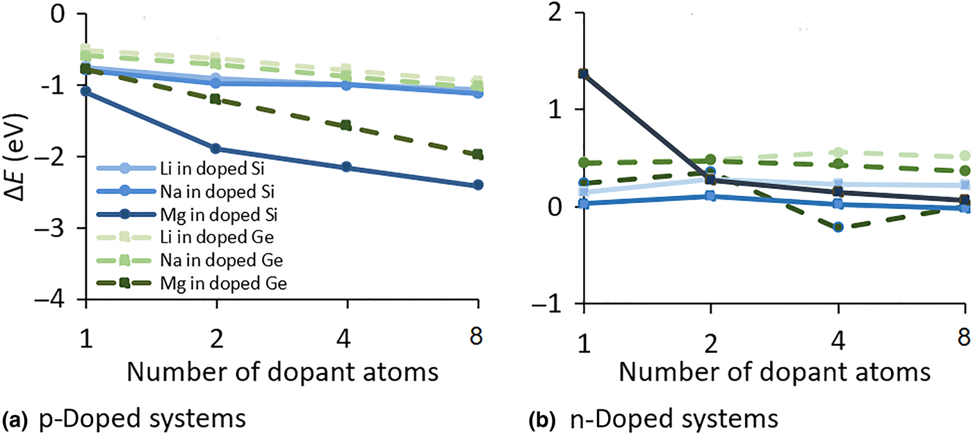
Figure 15 illustrates the change in formation energy due to explicit p- and n-doping relative to pristine material for both bulk Si and Ge, for the insertion of one Li/Na/Mg atom for different dopant concentrations. For p-doped systems, the formation energy is generally strengthened (between −0.5 and more than −2 eV), while in most cases the formation energy is weakened for n-doped systems. These changes can be correlated to changes in the Fermi level shown in Fig. 14. These results suggest the general beneficial nature of explicit doping for semiconductor electrode materials: increasing voltage and capacity with p-dopants and n-doping as a tool to increase conductivity (by occupying conduction states) without significantly reducing voltage and in some cases (e.g., Mg insertion into P4Si60) even gaining voltage due to structural defect-like effects related to strain.
Change in formation energy (∆E) in eV relative to bulk Li (light), Na and Mg (dark) in Si (blue) and Ge (green) due to p- and n-doping [(a) and (b), respectively] at different dopant concentrations.

Implicit doping: lithiation (sodiation, magnesiation) as p-doping
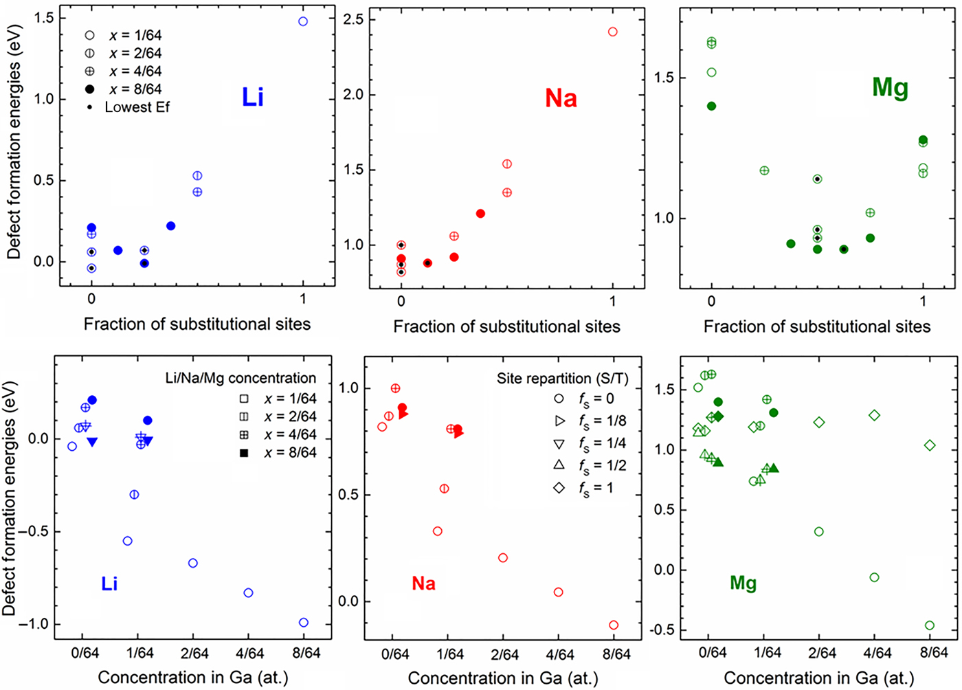
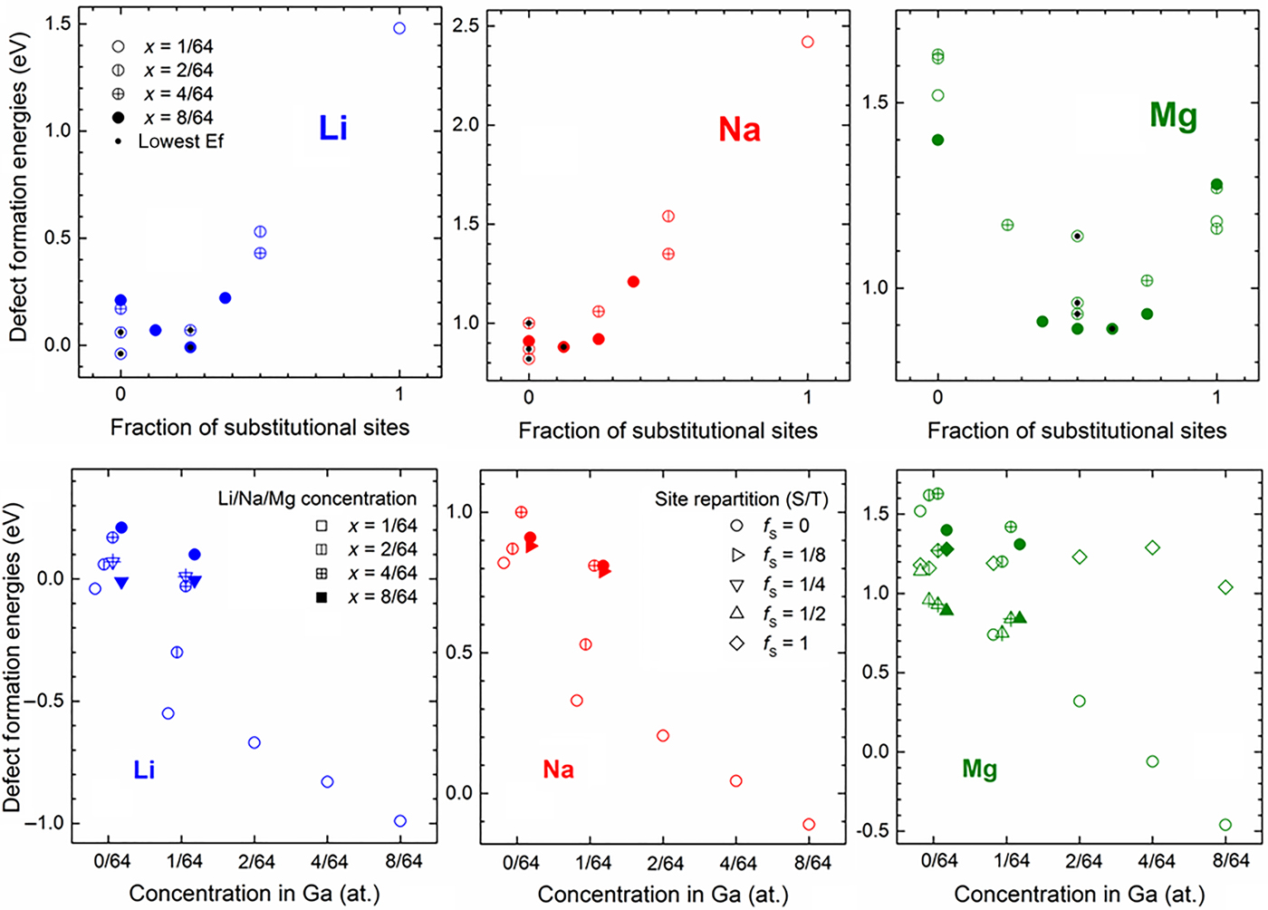
In Ref. Reference Legrain and Manzhos60, we explored the effect on binding strength of Li, Na, and Mg to germanium and p-doped germanium of different relative occupancies by Li, Na, and Mg of interstitial and substitutional sites. We found that the optimal balance of sites corresponds to a configuration in which the number of electrons donated by interstitial atoms is matched by the number of holes created by the substitutional defects. For example, inserted Mg atoms prefer to be distributed 50/50 between substitutional and interstitial sites, as each interstitial Mg donates two electrons (which would occupy states in the CB in the undoped material) and each substitutional Mg creates two holes in the frontier states of the valence band. In the case of Li and Na, the balance shifts toward more interstitial sites, as each substitutional Li or Na can be considered to create three holes, which can be filled with electrons from three interstitial atoms. This is shown in Fig. 16 (top panels). Note that a single Li or Na atom strongly prefers interstitial sites to substitutional ones (by about 1.5 and 2.5 eV, respectively). Yet, the insertion energy of four Li or four Na atoms is significantly lowered when one atom assumes the substitutional position. This is effectively a doping effect by Li/Na/Mg similar to the one described in the preceding sub-section, we will call it “implicit doping” below.
Defect formation energies (in eV) for Li/Na/Mg-doped Ge systems at different Li/Na/Mg concentrations (x = 1/64—empty circles, 2/64—circles with one vertical bar, 4/64—circles with two perpendicular bars, 8/64—full circles) and for different repartitions of tetrahedral and substitutional sites. The configurations with the lowest formation energies for each concentration are indicated with a black dot. The top panels show the insertion in pure Ge where the defect formation energies are plotted against the fraction of substitutional sites. The bottom panels show the defect formation energies for Li/Na/Mg insertion into Ga-doped Ge at different Ga concentrations. Reproduced with permission from Ref. Reference Legrain and Manzhos60. Copyright by AIP Publishing, 2017.
Interplay of explicit and implicit doping
The additional VB states created by Ga doping add to the holes due to implicit doping by substitutional Li/Na/Mg and change the balance between interstitial and substitutional sites during Li/Na/Mg insertion. The balance is tilted towards more interstitial sites as there are more holes to accommodate electrons donated by the interstitial sites (see Table S3 of Ref. Reference Legrain and Manzhos60). The end result is lower defect formation energies as is shown in the bottom row panels of Fig. 16. Specifically, Na and Mg insertion can be made thermodynamically favored versus formation of bulk Na and Mg, while it is not favored in pure Ge. This is therefore a viable strategy to enable or enhance Na or Mg storage.
Discussion and conclusion
Doping is a well-known technique to modify the electronic structure of materials by creating a newly occupied or unoccupied state within the band gap. While it is often applied to inorganic materials or organic polymers, its application can be extended to organic molecules and organic crystals.
We showed that substitutional p-doping applied to organic and inorganic active electrode materials for Li and Na ion batteries increases their electrode voltage. p-Doping has a large effect on the attachment of first Li or Na atoms in organic electrode materials and can increase the voltage by up to 3 V. On the other hand, p-doped inorganic materials considered here can increase their voltage by more than 2 V. This opens unique opportunities to design new active electrode materials; specifically, p-doping can enable electrochemical activity of host materials that are non-active before doping. Examples are Na insertion in Si and Ge and Li and Na attachment to coronene molecules. p-Doping can also help to achieve suitable cathodic voltages, specifically in organic electrode materials operating by reduction.[Reference Lüder, Cheow and Manzhos56] It must, however, be clearly distinguished between different effects of p-doping. First of all, single p-doping increases the voltage for insertion/attachment of the first Li/Na/Mg atoms in inorganic semiconductors by about 1 V and for molecules by 2–3 V. Consequently, p-doping also leads to an increase in theoretical capacity. The voltage drops, however, rapidly with increasing number of inserted/attached Li/Na/Mg atoms. In this regard, increasing the dopant concentration can increase the voltage for higher Li/Na/Mg concentrations. This is reflected to some extent in the amount of created hole states per formula unit in a material, i.e., the voltage drops rapidly after all hole states are filled. Moreover, increasing the p-dopant concentration can also increase the initial voltage by up to 1 V. Overall, the effect of p-doping is qualitatively similar in organic and inorganic materials.
In contrast to p-doping, n-doping shows significant differences in the effects on the voltage between organic and inorganic materials. For inorganic materials, we showed here that, in the case of bulk Si and Ge, n-doping makes the insertion of Li/Na/Mg less thermodynamically favored, i.e., it leads to a decrease in the voltage. This effect could be used, for example, to make voltages more suited for anodic operation (i.e., closer to 0 V). For molecules, n-doping can increase the voltage somewhat. This is caused mainly by strain effects (molecule is made less stable and therefore more reactive) and to a minor extent by electronic effects. In inorganic crystals, strain induced by doping has been shown to lead to higher defect formation energies (lower voltages) for Li/Na/Mg insertion.[Reference Legrain and Manzhos58, Reference Legrain and Manzhos60, Reference Legrain, Malyi and Manzhos61] Of course, this comparison should consider that the equivalent dopant concentrations considered here and elsewhere[Reference Lüder, Cheow and Manzhos56, Reference Legrain and Manzhos58, Reference Legrain and Manzhos60] for organic molecules are higher (one or more dopants per formula unit) than those reported for inorganic materials. We note that while Mg-binding energy can be significantly strengthened by p-doping of inorganic materials, this was not the case with organic materials studied here. The Mg-binding energy is very low and no significant charge donation to the molecules was observed for undoped and p-doped materials. Organic electrode materials for Mg ion batteries remain therefore an outstanding challenge.
As mentioned before, electronic effects like reorganization must be considered to understand n- and p-doping in both organic and inorganic materials. Both, substitutional p- and n-doping with atoms of different valence show similar effects on the band structure of organic and inorganic materials, i.e., creation of empty (p-doping) and occupied (n-doping) states in the DOS versus the pristine material. The main effect of p-doping is through band structure modification while for n-doping also structural effects including deformation, and lattice expansion/contraction, play an important role.[Reference Lüder, Cheow and Manzhos56, Reference Legrain and Manzhos58, Reference Legrain and Manzhos60]
It was shown that “pseudo” doping (i.e., substitutional doping with additional structural changes, e.g., the loss of an H atom, that may lead to additional changes of state occupation in a molecule) has a noticeable effect on the voltage profile and performance of organic electrode materials. “Pseudo”-like doping is frequently applied to molecules and polymers[Reference Heeger91] as it is an efficient tool (e.g., a substitution reaction) in organic chemistry/materials science to alter materials’ properties.[Reference Chen and Manzhos65, Reference Heeger91] Not all cases can be understood from simple approximations, as “pseudo” doping is more complex than adding/removing or keeping the amount of electrons (“frozen” states) in a material. Substitutions can also cause electronic relaxation/reorganization of the electronic structure that can lead to, e.g., band gap renormalization or band alignment shifts, which can be counter-intuitive to an over-simplified picture of e.g. “frozen” states. Electronic structure calculations can help elucidate these processes. While “pseudo” doping is here discussed for molecules, the concept is translated to inorganic solids by substitutional doping with an element of the same valence as the host (for the case of “pseudo”-doping keeping the amount of electrons the same).
In molecular materials, there is also a possibility to modulate the voltage by adding charge-withdrawing/donating groups known as functionalization.[Reference Heeger91–Reference Pelzer, Cheng and Curtiss94] Applied to, e.g., poly or oligomers,[Reference Chen and Manzhos65, Reference Heeger91, Reference Zhao, Lu and Chen92] their frontier orbitals shift either to higher or lower energies depending on the nature of the attached functional group. Through this shift, the voltage of active materials is modulated[Reference Chen and Manzhos65, Reference Heeger91, Reference Zhao, Lu and Chen92], which is argued to be a result of donation/depletion of charge from the unaltered part of the molecular material.[Reference Chen and Manzhos65, Reference Zhao, Lu and Chen92] The modulation of the frontier orbital energies in this way can have similar effects to those seen with substitutional doping. Indeed, doping by functionalization has been used.[Reference Coletti, Riedl, Lee, Krauss, Patthey, von Klitzing, Smet and Starke95, Reference Shim, Javey, Shi Kam and Dai96] Of course, the dopant causes charge reorganization additional to the creation of an additional empty/occupied state(s), which also leads to withdrawing/accumulating of electronic density from/to a redox active part of a molecule and consequently changing its affinity to accept electronic density from an attached Li/Na/Mg atom. Nonetheless, the two approaches are overall rather different, e.g., in terms of structural modifications, creation of empty/occupied states in the band gap and orbital engineering,[Reference Lüder, Cheow and Manzhos56, Reference Chen and Manzhos65, Reference Masaoka, Mukawa and Sakai97] while they have the same aim of improving the performance of active electrode materials. Therefore, they should be regarded as complementary approaches.
The interplay between n- and p-doping or combinations of different p/n-dopants could be of technological interest. Here, we have shown that lithiation (sodiation, magnesiation) of Ge can proceed by occupation of both interstitial sites (leading to n-doping) and substitutional sites (effectively p-doping) and that this combination leads to a higher voltage.
To conclude, in this “Prospective”, we demonstrate by means of ab initio modeling that explicit, implicit and “pseudo” (substitutional) doping are powerful tools that can be applied to both organic and inorganic materials to tailor material properties and improve the performance of electrode materials for advanced electrochemical batteries. This approach is general and therefore not restricted to the here presented prototypical materials; it can be applied to other battery materials used in, e.g., solid state and redox flow batteries since the main principle of modifying the frontier state and bandstructure as well as the use of strain effects remains. While doping increases the search space for the “best” electrode material for a particular type of organic and inorganic battery, it provides an additional degree of freedom in the design strategies. Since voltage enhancements of up to 3 V could be achieved, many previously unexplored or inefficient materials (including those with thermodynamically unfavored Li/Na/Mg insertion) could become working electrode materials after doping. Moreover, increasing or reducing an active material's voltage through substitutional doping can in principle be used to obtain a more suitable voltage profile for cathode/anode application, for instance, in materials with a voltage of 3 V like TCNQ or TCNE.[Reference Chen and Manzhos25, Reference Ratnakumar, Di Stefano, Williams, Nagasubramanian and Bankston27] The voltage could potentially be increased to values closer to 4 V with p-doping for more suitable cathodic operation. This may help overcome other technological challenges like safety, mechanical flexibility, or simply cost and environmental protection/regulations.
Acknowledgments
This work was supported by the Ministry of Education of Singapore AcRF Tier 2 grant MOE2014-T2-2-006.