1 Introduction
Granular matter is among the most utilized materials in industry (Williams Reference Williams1976; Ottino & Khakhar Reference Ottino and Khakhar2000) and covers a wide array of macroscopic particle conglomerations such as the sand in the deserts and the asteroids in our galaxy. Furthermore, properties reminiscent of solids as well as fluids can also be observed in granular media (Wieghardt Reference Wieghardt1975; Jaeger, Nagel & Behringer Reference Jaeger, Nagel and Behringer1996). For example, the granular matter can support the weight of large boulders on its surface or flow like a fluid on an inclined surface (Forterre & Pouliquen Reference Forterre and Pouliquen2008). The complex dynamics of granular matter governs many natural phenomena, including avalanches (Hutter et al. Reference Hutter, Koch, Pluüss and Savage1995), landslides (Savage & Hutter Reference Savage and Hutter1989) and earthquakes (Lu et al. Reference Lu, Hou, Jiang, Wang, Sun and Liu2018). Therefore, a proper understanding of granular media is of prime importance.
In a granular medium, grains interact through short-ranged contact forces (Cundall & Strack Reference Cundall and Strack1979). However, a few large particles placed in an agitated (Cattuto et al. Reference Cattuto, Brito, Marconi, Nori and Soto2006; Shaebani, Sarabadani & Wolf Reference Shaebani, Sarabadani and Wolf2012) or a sheared (Zuriguel et al. Reference Zuriguel, Boudet, Amarouchene and Kellay2005a) granular medium experience long-ranged attractive or repulsive interactions induced collectively by the grains. Few studies relate this attraction or repulsion between the intruders to the hydrodynamic fluctuations and a Bernoulli-like effect (Aumaître, Kruelle & Rehberg Reference Aumaître, Kruelle and Rehberg2001; Zuriguel et al. Reference Zuriguel, Boudet, Amarouchene and Kellay2005a; Cattuto et al. Reference Cattuto, Brito, Marconi, Nori and Soto2006; Pacheco-Vázquez & Ruiz-Suárez Reference Pacheco-Vázquez and Ruiz-Suárez2010; Shaebani et al. Reference Shaebani, Sarabadani and Wolf2012; Solano-Altamirano et al. Reference Solano-Altamirano, Caballero-Robledo, Pacheco-Vázquez, Kamphorst and Ruiz-Suárez2013). Some studies (Cruz & Caballero-Robledo Reference de la Cruz and Caballero-Robledo2016; Acevedo-Escalante & Caballero-Robledo Reference Acevedo-Escalante and Caballero-Robledo2017) consider this attraction or repulsion as a consequence of a passive failure in a Mohr–Coulomb material and jamming, respectively. Cattuto et al. (Reference Cattuto, Brito, Marconi, Nori and Soto2006) compared long-ranged repulsions to the Casimir effect since the fluctuations between two confined surfaces differ from the fluctuations on the open side of the intruders, thus leading to forces analogous to the Casimir effect. Although they observed only repulsion in their study, they predicted a cross-over to attraction after a certain distance if their system had a higher area fraction. Later, Shaebani et al. (Reference Shaebani, Sarabadani and Wolf2012) confirmed the occurrence of this behaviour in their study.
Many studies speculate that phenomena such as the brazil nut effect and segregation of granular matter may be a consequence of this attraction or repulsion between the larger particles (Aumaître et al. Reference Aumaître, Kruelle and Rehberg2001; Sanders et al. Reference Sanders, Swift, Bowley and King2004; Lozano et al. Reference Lozano, Zuriguel, Garcimartín and Mullin2015). In a study on the brazil nut effect, Sanders et al. (Reference Sanders, Swift, Bowley and King2004) discussed whether the congregation of the larger particles is a consequence of these attractive forces or if those particles have an affinity to collect in a particular region or space in a vertically shaken granular medium. They suggested that this congregation happens when a lower number density of the grains is observed in the region between the larger particles compared to the grain number density on the other side of the intruders. However, they agreed that their findings were not compatible with the assumptions and predictions of modified kinetic theory (Jenkins & Yoon Reference Jenkins and Yoon2002; Trujillo, Alam & Herrmann Reference Trujillo, Alam and Herrmann2003; Trujillo & Herrmann Reference Trujillo and Herrmann2003). Zuriguel et al. (Reference Zuriguel, Boudet, Amarouchene and Kellay2005a) studied the axial segregation of large particles in a partially filled horizontal rotating cylinder. They observed an equilibrium distance between the larger particles depending upon the rotational speed (or frequency) of the cylinder. There existed a threshold frequency  $f_{th}$ at which a cross-over from attraction to repulsion occurs. They explained the attraction in terms of the velocity fluctuations or the granular temperature by suggesting that the pressure is directly proportional to the velocity fluctuations. Since the grains in the region between the larger particles had lower velocity fluctuations than the grains outside this region, this led to a net attractive force at low rotational frequencies. However, for the repulsion, they argued that the fluctuations in the velocities were much smaller than the mean velocities above the threshold frequency
 $f_{th}$. Therefore, as per Bernoulli’s equation, higher pressure will exist where the mean velocity is low; this would lead to repulsive forces owing to a net pressure difference across the intruders. However, their explanations were rather a priori and need further investigation.
The attraction or repulsion between the larger intruders has been studied recently by Pacheco-Vázquez & Ruiz-Suárez (Reference Pacheco-Vázquez and Ruiz-Suárez2010) where they investigated the dynamics of a group of intruders penetrating collectively inside a granular medium having very low yield stress. They observed that the intruders aligned in a way similar to the V-flock formation of birds to move efficiently. Another important finding of this work is the length scale associated with repulsion and attraction; if the separation between the intruders is below a given value (which is a function of grain diameter, and not intruder diameter), the flow of grains between the intruders would be hindered due to jamming similar to the case of a silo (Zuriguel et al. Reference Zuriguel, Garcimartín, Maza, Pugnaloni and Pastor2005b, Reference Zuriguel, Janda, Garcimartín, Lozano, Arévalo and Maza2011; Reddy et al. Reference Reddy, Kumar, Anki Reddy and Talbot2018), thus, leading to a repulsion. Solano-Altamirano et al. (Reference Solano-Altamirano, Caballero-Robledo, Pacheco-Vázquez, Kamphorst and Ruiz-Suárez2013) also observed that repulsion occurred when the distance between the intruders was less than  $6d$, where
 $d$ is the grain diameter, in the same experimental set-up as Pacheco-Vázquez & Ruiz-Suárez (Reference Pacheco-Vázquez and Ruiz-Suárez2010). Nelson et al. (Reference Nelson, Katsuragi, Mayor and Durian2008) in the similar context also tried to capture the interactions between the intruder and the wall.
Contrary to previous studies, Cruz & Caballero-Robledo (Reference de la Cruz and Caballero-Robledo2016) studied the forces between two large intruders fixed in a vertical chute flow and proposed a non-Bernoulli origin for the forces. Instead of defining the regions in the space between the intruders, they considered two regions that lie upstream of the intruders. They observed that, when the intruders are at separations  ${<}10d$, the repulsive forces are not of Bernoulli origin but due to jamming of the particles. However, Zuriguel et al. (Reference Zuriguel, Boudet, Amarouchene and Kellay2005a) observed this repulsion at separations that were much larger than the ones seen in Cruz & Caballero-Robledo (Reference de la Cruz and Caballero-Robledo2016). It is well known that, in silos, jamming occurs when the aperture size is below a critical value (Zuriguel et al. Reference Zuriguel, Garcimartín, Maza, Pugnaloni and Pastor2005b, Reference Zuriguel, Janda, Garcimartín, Lozano, Arévalo and Maza2011; Reddy et al. Reference Reddy, Kumar, Anki Reddy and Talbot2018) and Zuriguel et al. (Reference Zuriguel, Boudet, Amarouchene and Kellay2005a) observed repulsion at distances far higher than these values. On the contrary, Cruz & Caballero-Robledo (Reference de la Cruz and Caballero-Robledo2016) observed repulsion at distances in the same range as this critical value where jamming is more frequent due to small aperture size, as in silos. Therefore, although Cruz & Caballero-Robledo (Reference de la Cruz and Caballero-Robledo2016) provided the explanation that is correct for their system due to frequent jamming, it did not describe the repulsion observed in other studies (Aumaître et al. Reference Aumaître, Kruelle and Rehberg2001; Sanders et al. Reference Sanders, Swift, Bowley and King2004; Zuriguel et al. Reference Zuriguel, Boudet, Amarouchene and Kellay2005a) where jamming is less frequent; however, both explanations are empirical. The granular pressure needs to be compared with the quantities such as the local velocity fluctuations and mean velocity in order to ascertain the origin of these attractive or repulsive forces.
In this paper, we study the forces between two intruders that are fixed at a given distance from each other and move horizontally at a constant velocity inside the granular medium. We explore the origin of the attractive and repulsive forces by investigating the granular pressure and the quantities used to explain these forces in earlier studies (Sanders et al. Reference Sanders, Swift, Bowley and King2004; Zuriguel et al. Reference Zuriguel, Boudet, Amarouchene and Kellay2005a; Solano-Altamirano et al. Reference Solano-Altamirano, Caballero-Robledo, Pacheco-Vázquez, Kamphorst and Ruiz-Suárez2013; Cruz & Caballero-Robledo Reference de la Cruz and Caballero-Robledo2016). We also explore the effect of friction, intruder velocity and pressure head in our system. Our work helps in identifying the origin of these long-ranged forces in the evolution and the subsequent buckling of force chains, which may be an essential step in understanding the segregation and brazil nut effect in granular media.
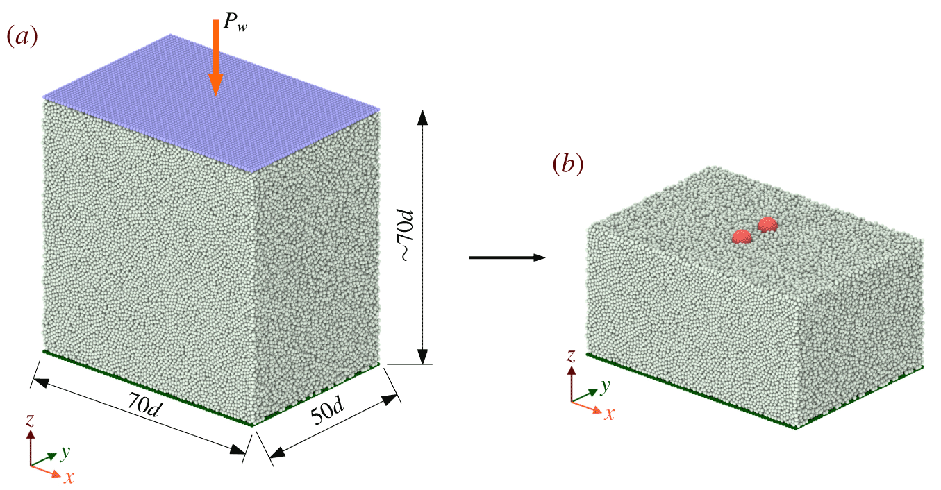
(a) Shows the initial configuration for  $L-D=5d$. The top wall (blue) acts as a piston and applies a pressure of
 $P_{w}$ on the granular bed. (b) Shows the system below the plane
 $z=0$ to reveal the location of the intruders. The intruders have a separation of
 $L$ from each other’s centres, and they have a gap of
 $L-D$ between them. A gravity of magnitude
 $g$ acts in the negative
 $z$-direction and both the intruders are moved at a constant velocity in the positive
 $x$-direction. The origin is at the centre of the system which coincides with the midpoint of line joining the centre of the two intruders. Axes are given as a guide to the eye.

2 Simulation methodology
The discrete element method, proposed by Cundall & Strack (Reference Cundall and Strack1979), has been employed in our numerical study to investigate the forces on two intruders moving in a granular bed in three dimensions. The mean diameter of grains in our system is  $d$ with a polydispersity of ten per cent. The initial configuration of the system, as shown in figure 1, is created by fixing two spheres of diameter
 $D=5d$ at a centre-to-centre distance of
 $L$ and then pouring 293 000 grains into a system of size
 $70d\times 50d$ along the
 $x$ and
 $y$ directions, respectively. The granular bed attains a height of approximately
 $70d$ along the
 $z$ direction when the grains settle due to gravity. Due to dissipative interactions and friction, the grains lose energy. A gravity of magnitude
 $g$ is present in the system along
 $-z$, and a fixed bottom wall at
 $z=-35d$ supports the weight of the grains. A wall, behaving as a piston, applying a pressure
 $P_{w}$, is placed at the top surface. The
 $x$-direction is periodic while two flat walls confine the
 $y$-direction (at
 $y=\pm 25d$). The intruders are kept in the
 $xy$ plane at
 $z=0d$ and the origin of the system lies at the centre of the line joining the intruders. The intruders move at constant velocity along the
 $x$-direction and, since there is no relative velocity between the intruders, the centre-to-centre distance between the intruders remains const. (
 $=L$). It is ensured that the energy in the system is approximately zero before we perform our simulations.
We consider the force model proposed by Brilliantov et al. (Reference Brilliantov, Spahn, Hertzsch and Pöschel1996), Silbert et al. (Reference Silbert, Ertaş, Grest, Halsey, Levine and Plimpton2001), as shown in (2.1), to calculate the normal and tangential contact forces,  $\boldsymbol{F}_{n}^{ij}$ and
 $\boldsymbol{F}_{t}^{ij}$, between two grains
 $i$ and
 $j$ whose positions are at
 $\boldsymbol{r}_{i}$ and
 $\boldsymbol{r}_{j}$, respectively, that are in contact at a given time
 $t$. The grains have masses
 $m_{i}=\unicode[STIX]{x1D70C}\unicode[STIX]{x03C0}d_{i}^{3}/6$ and
 $m_{j}=\unicode[STIX]{x1D70C}\unicode[STIX]{x03C0}d_{j}^{3}/6$, where
 $d_{i}$ and
 $d_{j}$ are the diameters of grain
 $i$ and
 $j$, and
 $\unicode[STIX]{x1D70C}$ is the density of the grains.
 $$\begin{eqnarray}\left.\begin{array}{@{}c@{}}\displaystyle \boldsymbol{F}_{n}^{ij}=\sqrt{R_{eff}\unicode[STIX]{x1D6FF}}(k_{n}\unicode[STIX]{x1D6FF}\boldsymbol{n}_{ij}-m_{eff}\unicode[STIX]{x1D6FE}_{n}\boldsymbol{v}_{n}^{ij})\\ \displaystyle \boldsymbol{F}_{t}^{ij}=-\sqrt{R_{eff}\unicode[STIX]{x1D6FF}}(k_{t}\unicode[STIX]{x1D71F}s_{t}+m_{eff}\unicode[STIX]{x1D6FE}_{t}\boldsymbol{v}_{t}^{ij}).\end{array}\!\right\}\end{eqnarray}$$
Here,  $k_{n}=2\times 10^{6}\unicode[STIX]{x1D70C}dg$ and
 $k_{t}=2.453\times 10^{6}\unicode[STIX]{x1D70C}dg$ are the nonlinear spring constants,
 $\unicode[STIX]{x1D6FF}=(d_{i}+d_{j})/2-|\boldsymbol{r}_{i}-\boldsymbol{r}_{j}|$ is the overlap between the grains and
 $\boldsymbol{n}_{ij}=(\boldsymbol{r}_{i}-\boldsymbol{r}_{j})/|\boldsymbol{r}_{i}-\boldsymbol{r}_{j}|$ is the unit vector joining the centres of grains
 $i$ and
 $j$. Two grains are in contact only if
 $\unicode[STIX]{x1D6FF}\geqslant 0$. The normal relative velocity
 $\boldsymbol{v}_{n}^{ij}$ and tangential relative velocity
 $\boldsymbol{v}_{t}^{ij}$ are given as
 $$\begin{eqnarray}\left.\begin{array}{@{}c@{}}\displaystyle \boldsymbol{v}_{n}^{ij}=((\dot{\boldsymbol{r}}_{i}-\dot{\boldsymbol{r}}_{j}+\unicode[STIX]{x1D74E}_{i}\times (d_{i}\boldsymbol{n}_{ij})/2-\unicode[STIX]{x1D74E}_{j}\times (d_{j}\boldsymbol{n}_{ij})/2)\cdot \boldsymbol{n}_{ij})\boldsymbol{n}_{ij},\\ \displaystyle \boldsymbol{v}_{t}^{ij}=((\dot{\boldsymbol{r}}_{i}-\dot{\boldsymbol{r}}_{j}+\unicode[STIX]{x1D74E}_{i}\times (d_{i}\boldsymbol{n}_{ij})/2-\unicode[STIX]{x1D74E}_{j}\times (d_{j}\boldsymbol{n}_{ij})/2))-\boldsymbol{v}_{n}^{ij}.\end{array}\right\}\end{eqnarray}$$
Here,  $\unicode[STIX]{x1D74E}_{i}$ and
 $\unicode[STIX]{x1D74E}_{j}$ are the angular velocities of grains
 $i$ and
 $j$, respectively. The damping coefficients
 $\unicode[STIX]{x1D6FE}_{n}$ and
 $\unicode[STIX]{x1D6FE}_{t}$ are taken as
 $1500\sqrt{g/d^{3}}$, and
 $\unicode[STIX]{x1D71F}s_{t}$ is the tangential displacement vector. For a given pair of contacts,
 $m_{eff}=m_{1}m_{2}/(m_{1}+m_{2})$ and
 $R_{eff}=d_{1}d_{2}/2(d_{1}+d_{2})$ are the effective mass and effective radius, respectively. The upper limit of
 $\boldsymbol{F}_{t}^{ij}$ is restricted to
 $\unicode[STIX]{x1D707}\boldsymbol{F}_{n}^{ij}$ beyond which the contacts slip where
 $\unicode[STIX]{x1D707}$ is the coefficient of friction.
The intruders move with a velocity of  $V\hat{\boldsymbol{x}}$, where
 $\hat{\boldsymbol{x}}$ is the unit vector in the
 $x$-direction. Moreover, the top wall applies a pressure of
 $P_{w}$ on the system. The time step
 $dt$ in the simulations is taken as
 $10^{-4}\sqrt{d/g}$ and the simulation is carried out for the time it takes the intruders to travel
 $350d$ in the system along
 $x$. The forces on the intruders are recorded after every 5
 $dt$, and the average force is calculated after the system has reached a mean ‘steady’ state, i.e. the forces fluctuate around a well-defined mean. The value of
 $\unicode[STIX]{x1D707}$ in our simulations is 0.5 unless mentioned otherwise. We ensure that the periodic boundaries did not affect the dynamics of the system. The simulations start at time
 $t=0$.
All the simulations are carried out in LAMMPS (Plimpton, Crozier & Thompson Reference Plimpton, Crozier and Thompson2007) and the post-simulation visualization is done using OVITO (Stukowski Reference Stukowski2009).
3 Results and analysis
In this section, we present the results of our numerical study. The means of quantities such as the drag force  $F_{D}$ and sideways force
 $F_{S}$ are calculated by averaging their instantaneous values after a mean steady-state behaviour is achieved. The stress tensor
 $\unicode[STIX]{x1D70E}_{R}(t)$ and pressure
 $P_{R}(t)$ in any region
 $R$ at time
 $t$ are calculated according to the following scheme shown in (3.1) (Drescher & de Josselin de Jong Reference Drescher and de Josselin de Jong1972; Guillard, Forterre & Pouliquen Reference Guillard, Forterre and Pouliquen2014; Seguin et al. Reference Seguin, Coulais, Martinez, Bertho and Gondret2016):
 $$\begin{eqnarray}\unicode[STIX]{x1D70E}_{R}(t)=\frac{1}{V_{R}}\mathop{\sum }_{i\neq j}^{Region\,R}(\boldsymbol{F}^{ij}\otimes \boldsymbol{r}_{ij}).\end{eqnarray}$$
Here,  $\boldsymbol{F}^{ij}$ is the contact force between grains
 $i$ and
 $j$ whose point of contact lies in the region
 $R$,
 $V_{R}$ is the volume of the region
 $R$ and
 $\boldsymbol{r}_{ij}$ is the position vector of the point of contact. The pressure is then calculated as
 $P_{R}(t)=-\frac{1}{3}\text{Tr}(\unicode[STIX]{x1D70E}_{R}(t))$. We define the pressure head
 $P_{head}$ acting on the intruders as the pressure in the region
 $z=\pm d$ before we initiate the motion of the intruders;
 $P_{head}=P_{z=\pm d}(t=0)/\unicode[STIX]{x1D70C}dg$. We vary
 $P_{head}$ by changing the pressure exerted by top wall
 $P_{w}$.
3.1 Comparison of forces in system of two intruders with that of a single intruder
In this subsection, we present the number of contacts  $N_{c}$, drag
 $F_{D}$ and sideways force
 $F_{S}$ for two separate cases: (i) the two moving intruders located symmetrically along the central
 $xz$-plane in the system, and (ii) a single moving intruder located at the same location in the system as one of the two intruders in the previous case. The coefficient of friction is kept at
 $\unicode[STIX]{x1D707}=0.5$ and the intruder moves at a velocity of
 $V=1.0\sqrt{dg}$. The pressure head for this subsection is fixed as
 $P_{head}=47.7$.
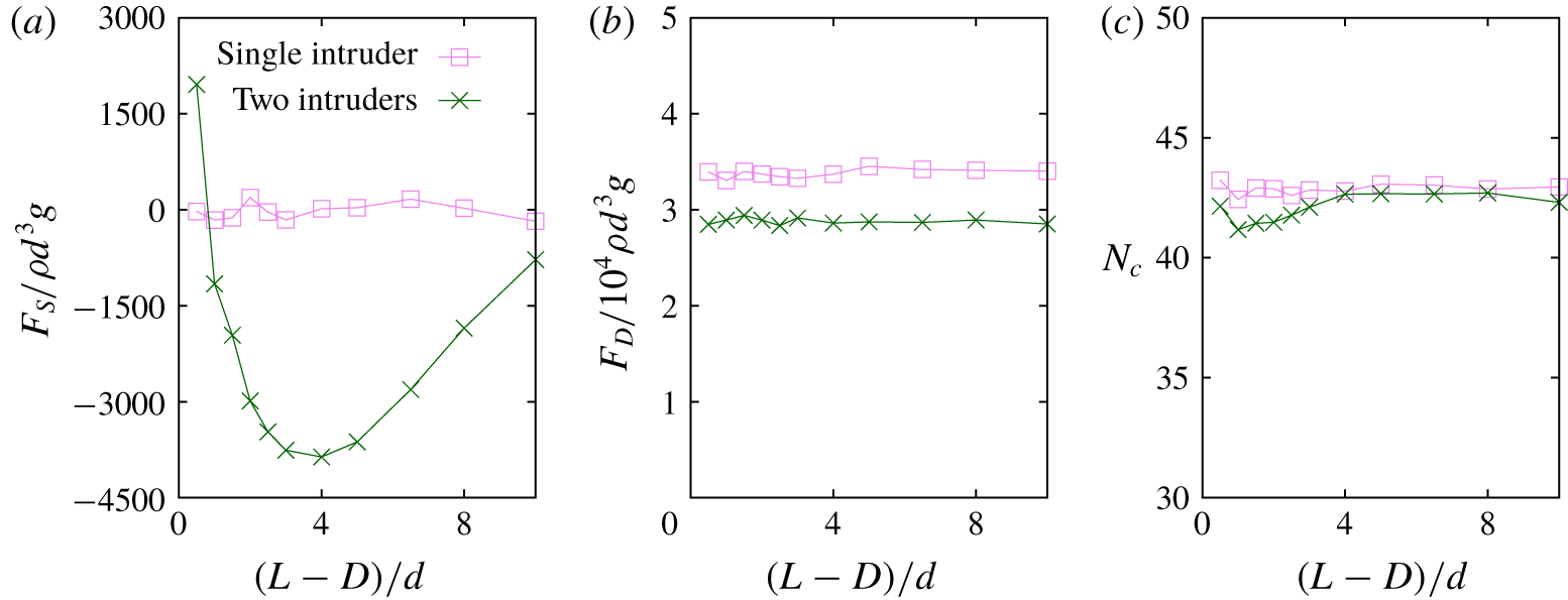
In figure 2(a), we plot the sideways force  $F_{S}$ against the gap between the intruders
 $L-D$. The positive sign of
 $F_{S}$ represents repulsive force between the intruders while the negative sign suggests an attractive force. Even though the single intruder is not moving in a perfectly symmetric environment,
 $F_{S}\approx 0$ suggests that the presence of wall is not inducing enough asymmetry to result in a considerable sideways force. On the contrary, if two intruders are present, a sideways force is observed whose magnitude is a function of the separation between the intruders
 $L-D$ which indicates that the asymmetry is induced mostly by the other intruder. Repulsion exists between the intruders at low
 $L-D$ which transitions to an attractive sideways force for large separation between the intruders. Additionally, the attraction force reaches a maximum at a particular
 $L-D$. These results are in accordance with those observed in the works of Cruz & Caballero-Robledo (Reference de la Cruz and Caballero-Robledo2016). We will address the origin of these attraction and repulsion forces in further subsections.
Plots showing (a) sideways force  $F_{S}$, (b) drag force
 $F_{D}$ and (c) number of contacts
 $N_{c}$ versus
 $L-D$ for single and two intruder system. Here
 $P_{head}=47.7$,
 $V=1.0\sqrt{dg}$ and
 $\unicode[STIX]{x1D707}=0.5$. For the single intruder,
 $L-D$ represents the gap between the intruders if the other intruder was present. The plots are non-dimensionalized with respect to
 $\unicode[STIX]{x1D70C}$,
 $d$ and
 $g$. The symbols in (b,c) mean the same as in (a).

The variation in the drag  $F_{D}$ is much lower than
 $F_{S}$ at various
 $L-D$, as shown in figure 2(b). However, the drag is higher for the case of single intruder in comparison with that of the two intruders. When an object moves in a granular medium, the coexisting creation and failure of force chains as it moves forward generates the drag force (Albert et al. Reference Albert, Pfeifer, Barabási and Schiffer1999; Geng & Behringer Reference Geng and Behringer2004, Reference Geng and Behringer2005). However, when two intruders are moving, they buckle the force chains together due to being only a few grains away from each other, resulting in lower drag. This has been observed in another study by Reddy, Forterre & Pouliquen (Reference Reddy, Forterre and Pouliquen2011), where they showed the role of mechanically activated processes in granular media. They observed that the force required to move a rod in a granular medium decreased if shearing was introduced a few grains away from the rod by a rotating cylinder. The number of contacts
 $N_{c}$ of the intruder with grains is seen to be almost constant with
 $L-D$ (see figure 2c).
3.2 Effect of pressure head  $P_{head}$, velocity $V$ and friction coefficient $\unicode[STIX]{x1D707}$


In this subsection, we study the effect of pressure head  $P_{head}$, the velocity of the intruder
 $V$ and the friction coefficient
 $\unicode[STIX]{x1D707}$ to investigate if the trends observed in the previous subsection are an artefact of the given conditions or if similar trends exist if we alter the conditions. While studying the effect of variation of one of the quantities (
 $P_{head},$
 $V$ and
 $\unicode[STIX]{x1D707}$), we keep the other two quantities constant. We also shed some light on the origin of the attractive and repulsive natures of these forces in this subsection.
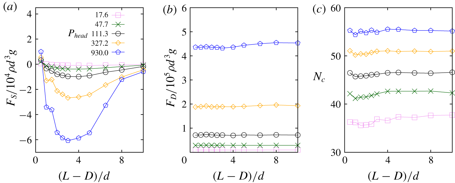
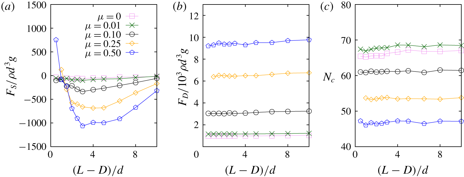
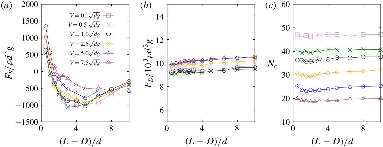
The sideways force  $F_{S}$ versus
 $L-D$ is shown in figure 3(a) for various
 $P_{head}$, in figure 4(a) for various
 $\unicode[STIX]{x1D707}$ and in figure 5(a) for various
 $V$. In all the cases, trends are similar, with the repulsion between the intruders occurring at lower
 $L-D$, and attraction at higher
 $L-D$. There also exists a
 $L-D$ at which attraction is maximum between the intruders. The separation between the intruders at which transition occurs from repulsion to attraction remains almost the same for various
 $P_{head}$. Moreover, the maximum attraction also occurs at almost the same
 $L-D$ irrespective of
 $P_{head}$ at a constant
 $V$ and
 $\unicode[STIX]{x1D707}$. However, the separation at which maximum attraction occurs seems to change with
 $V$ and
 $\unicode[STIX]{x1D707}$. Additionally, the separation at which repulsion to attraction transition occurs also seems to change with the intruder velocity (
 $V$) and coefficient of friction (
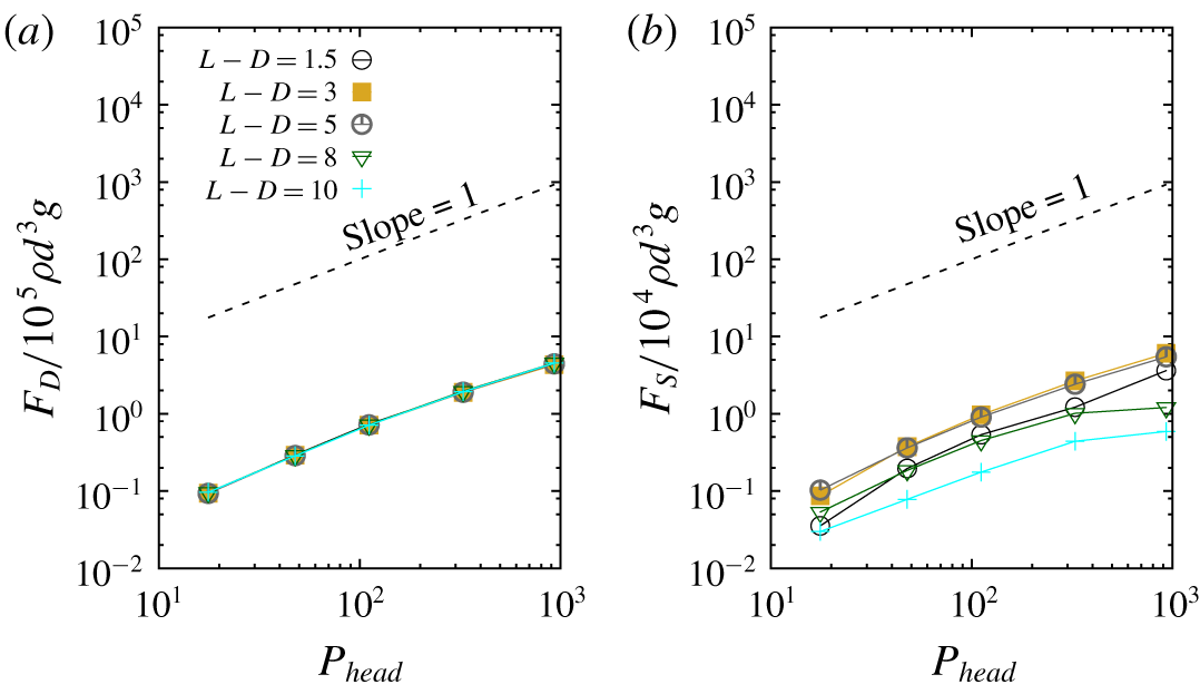
 $\unicode[STIX]{x1D707}$). Figure 6(a) shows the linear dependency of
 $F_{S}$ on
 $P_{head}$ for various
 $L-D$ on a log–log scale.
Plots showing (a) sideways force  $F_{S}$, (b) drag force
 $F_{D}$ and (c) number of contacts
 $N_{c}$ versus
 $L-D$ for two intruder system for various pressure head
 $P_{head}$. Here,
 $V=1.0\sqrt{dg}$ and
 $\unicode[STIX]{x1D707}=0.5$. The plots are non-dimensionalized with respect to
 $\unicode[STIX]{x1D70C}$,
 $d$ and
 $g$. The symbols in (b,c) mean the same as in (a).

Plots showing (a) sideways force  $F_{S}$, (b) drag force
 $F_{D}$ and (c) number of contacts
 $N_{c}$ versus
 $L-D$ for two intruder system for various
 $\unicode[STIX]{x1D707}$. Here
 $P_{head}=47.7$ and
 $V=1.0\sqrt{dg}$. The plots are non-dimensionalized with respect to
 $\unicode[STIX]{x1D70C}$,
 $d$ and
 $g$. The symbols in (b,c) mean the same as in (a).

Plots showing (a) sideways force  $F_{S}$, (b) drag force
 $F_{D}$ and (c) number of contacts
 $N_{c}$ versus
 $L-D$ for two intruder system for various velocities
 $V$. Here
 $P_{head}=47.7$ and
 $\unicode[STIX]{x1D707}=0.5$. The plots are non-dimensionalized with respect to
 $\unicode[STIX]{x1D70C}$,
 $d$ and
 $g$. The symbols in (b,c) mean the same as in (a).

Plots showing the linear dependency of (a) sideways force and (b) drag force with pressure head at various  $L-D$. The symbols in (b) mean the same as in (a).

The drag force  $F_{D}$ versus
 $L-D$ is shown in figure 3(b) for various
 $P_{head}$, in figure 4(b) for various
 $\unicode[STIX]{x1D707}$ and in figure 5(b) for various
 $V$. The drag is seen to be almost constant with increasing
 $L-D$ for a given
 $P_{head}$,
 $V$, and
 $\unicode[STIX]{x1D707}$. The drag increases linearly with
 $P_{head}$, as shown in figure 6(b), and also increases with
 $\unicode[STIX]{x1D707}$, similar to the earlier studies (Kumar et al. Reference Kumar, Anki Reddy, Takada and Hayakawa2017). However, the drag does not have a clear correlation with the velocity
 $V$. The closest explanation can be understood in the work of Hilton & Tordesillas (Reference Hilton and Tordesillas2013), where they suggest that
 $F_{D}$ remains constant until a velocity of
 $\sqrt{Dg/2}/2$ and then increases linearly.
The number of contacts  $N_{c}$ (the total number of contacts an intruder has with the grains averaged over both intruders) versus
 $L-D$ is shown in figure 3(c) for various
 $P_{head}$, in figure 4(c) for various
 $\unicode[STIX]{x1D707}$ and in figure 5(c) for various
 $V$. The number of contacts
 $N_{c}$ appears to be almost constant for
 $L-D$ for a given
 $P_{head}$,
 $V$ and
 $\unicode[STIX]{x1D707}$.
3.3 Angular distribution of quantities around the intruder
In this subsection, we have plotted the distribution of quantities around the intruders such as pressure  $P$, granular temperature
 $T$, volume fraction
 $\unicode[STIX]{x1D6F7}$, velocity squared in the frame of the intruder
 $v^{2}$ and the number of contacts
 $N$ that a grain makes with other grains at a distance of
 $(D+d)/2$ from the intruder centre, where a majority of the intruder contacts are present. In order to calculate these quantities at a given point
 $K$, we use Lucy’s coarse graining function (Lucy Reference Lucy1977) as per the scheme mentioned in the works of Weinhart et al. (Reference Weinhart, Hartkamp, Thornton and Luding2013) and Guillard et al. (Reference Guillard, Forterre and Pouliquen2014). Let us say that the point
 $K$ has a position vector
 $\boldsymbol{r}_{K}$; we then determine the quantities at
 $K$ as per the following scheme:
 $$\begin{eqnarray}\displaystyle & \displaystyle \unicode[STIX]{x1D6F7}(t)=\left[\mathop{\sum }_{i=1}^{n}\left.\left(\frac{\unicode[STIX]{x1D70C}\unicode[STIX]{x03C0}d_{i}^{3}}{6}\right){\mathcal{W}}(\boldsymbol{r}_{K}-\boldsymbol{r}_{i}(t))\right]\right/\unicode[STIX]{x1D70C}, & \displaystyle\end{eqnarray}$$
 $$\begin{eqnarray}\displaystyle & \displaystyle \boldsymbol{v}(t)=\left.\left[\mathop{\sum }_{i=1}^{n}\left(\frac{\unicode[STIX]{x1D70C}\unicode[STIX]{x03C0}d_{i}^{3}}{6}\right)(\dot{\boldsymbol{r}}_{i}(t)-V\hat{\boldsymbol{x}}){\mathcal{W}}(\boldsymbol{r}_{K}-\boldsymbol{r}_{i}(t))\right]\right/\unicode[STIX]{x1D70C}\unicode[STIX]{x1D6F7}, & \displaystyle\end{eqnarray}$$
 $$\begin{eqnarray}\displaystyle & \displaystyle T(t)=\frac{\displaystyle \mathop{\sum }_{i=1}^{n}\left(\frac{\unicode[STIX]{x1D70C}\unicode[STIX]{x03C0}d_{i}^{3}}{6}\right)|(\dot{\boldsymbol{r}}_{i}(t)-V\hat{\boldsymbol{x}}-\boldsymbol{v})|^{2}{\mathcal{W}}(\boldsymbol{r}_{K}-\boldsymbol{r}_{i}(t))}{3\unicode[STIX]{x1D70C}\unicode[STIX]{x1D6F7}}-\dot{\unicode[STIX]{x1D6FE}}^{2}c^{2}/12, & \displaystyle\end{eqnarray}$$
 $$\begin{eqnarray}\displaystyle & \displaystyle N(t)=\left[\mathop{\sum }_{i=1}^{n}\left.\left(\frac{\unicode[STIX]{x1D70C}\unicode[STIX]{x03C0}d_{i}^{3}}{6}\right)N_{i}^{\prime }{\mathcal{W}}(\boldsymbol{r}_{K}-\boldsymbol{r}_{i}(t))\right]\right/\unicode[STIX]{x1D70C}\unicode[STIX]{x1D6F7}, & \displaystyle\end{eqnarray}$$
 $$\begin{eqnarray}\displaystyle & \displaystyle \unicode[STIX]{x1D70E}_{ij}(t)=\mathop{\sum }_{i=1}^{n}\mathop{\sum }_{j=i+1}^{n}(\boldsymbol{F}^{ij}\times \boldsymbol{r}_{ij})\int _{s=0}^{1}{\mathcal{W}}(\boldsymbol{r}_{K}-\boldsymbol{r}_{i}(t)+s\boldsymbol{r}_{ij})\,\text{d}s, & \displaystyle\end{eqnarray}$$
 $$\begin{eqnarray}\displaystyle & \displaystyle P(t)=\frac{-\text{tr}(\unicode[STIX]{x1D70E}_{ij}(t))}{3}, & \displaystyle\end{eqnarray}$$
 $$\begin{eqnarray}\displaystyle & \displaystyle {\mathcal{W}}(\boldsymbol{r})=\frac{105}{16\unicode[STIX]{x03C0}c^{3}}(-3(r/c)^{4}+8(r/c)^{3}-6(r/c)^{2}+1). & \displaystyle\end{eqnarray}$$
Here,  $\unicode[STIX]{x1D6F7}(t),\boldsymbol{v}(t),T(t),N(t),\unicode[STIX]{x1D70E}_{ij}(t)$ and
 $P(t)$ are volume fraction, velocity vector, granular temperature, number of contacts, stress tensor and pressure at a point
 $K$ at a given time
 $t$. When referred to as
 $\unicode[STIX]{x1D6F7},\boldsymbol{v},T,N,\unicode[STIX]{x1D70E}_{ij}$ and
 $P$, they represent their time-averaged counterparts at
 $K$;
 ${\mathcal{W}}(\boldsymbol{r})$ is Lucy’s coarse graining function and
 $c$ is a constant equal to
 $1.0d$. Lucy’s function is evaluated for all the grains from 0 to
 $n$ that satisfy
 $|\boldsymbol{r}_{K}-\boldsymbol{r}_{i}|<c$, each having a position vector of
 $\boldsymbol{r}_{i}$ and number of contacts
 $N_{i}^{\prime }$. We have added a correction factor for the granular temperature, as suggested by Weinhart et al. (Reference Weinhart, Hartkamp, Thornton and Luding2013). In our system,
 $\dot{\unicode[STIX]{x1D6FE}}$ is obtained from the coarse grained velocity field for obtaining the correction term of granular temperature.
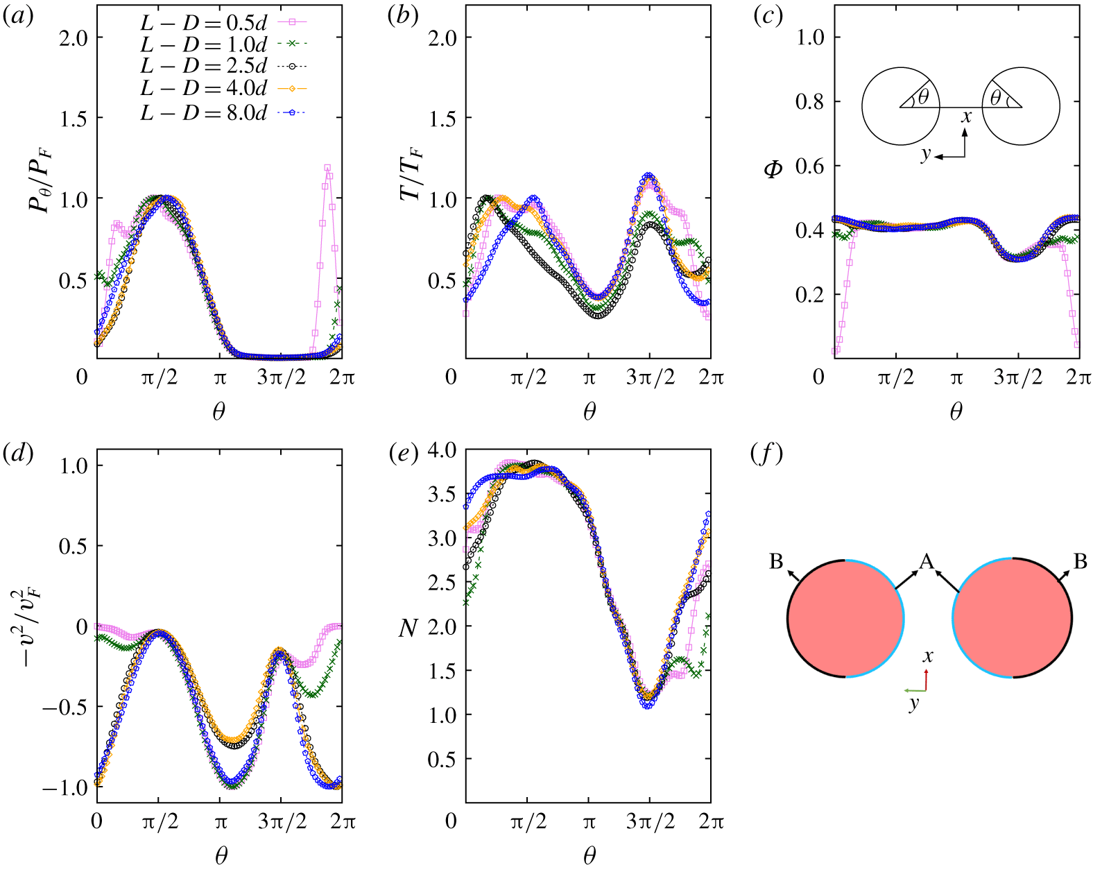
Plots showing the angular distribution around the intruder at a distance of $(D+d)/2$ for (a) pressure
 $P_{\unicode[STIX]{x1D703}}$ at a given angle
 $\unicode[STIX]{x1D703}$ normalized by
 $P_{F}$, (b) granular temperature
 $T$ normalized by its upstream maxima
 $T_{F}$, (c) volume fraction
 $\unicode[STIX]{x1D6F7}$, (d) square of the velocity magnitude
 $v^{2}$ with respect to the intruder normalized by its upstream maxima
 $v_{F}^{2}$ and (e) number of contacts
 $N$ versus the angle
 $\unicode[STIX]{x1D703}$ with respect to the intruder as displayed in (c). (f) The schematic shows the location of the two hemispheres A and B. The intruders move in the
 $x$-direction. The symbols in (b–e) mean the same as in (a).

In order to understand the sideways force, we investigate the angular distribution of pressure  $P_{\unicode[STIX]{x1D703}}$ at a distance of
 $(D+d)/2$ from the centre of the intruders, normalized with respect to their maxima
 $P_{F}$ on the front of the intruder
 $(0\leqslant \unicode[STIX]{x1D703}\leqslant \unicode[STIX]{x03C0})$ for the plane
 $z=0$ as shown in figure 7(a). Here,
 $\unicode[STIX]{x1D703}$ has been taken as shown in the inset of figure 7(c). Consider the intruder is divided into two hemispheres A and B along the
 $xz$ plane passing through the centre of the intruder as shown in figure 7(f). Here, hemisphere A points in the direction of the other intruder and hemisphere B is facing the wall. We find that, at lower
 $L-D$, the net pressure is higher on hemisphere A
 $(0\leqslant \unicode[STIX]{x1D703}\leqslant \unicode[STIX]{x03C0}/2\cup 3\unicode[STIX]{x03C0}/2<\unicode[STIX]{x1D703}\leqslant 2\unicode[STIX]{x03C0})$ in comparison to the net pressure on hemisphere B
 $(\unicode[STIX]{x03C0}/2\leqslant \unicode[STIX]{x1D703}\leqslant 3\unicode[STIX]{x03C0}/2)$, thus, leading to a net repulsion. However, as
 $L-D$ increases, the net pressure on A decreases to the point that it is lower than the pressure on hemisphere B, causing an attraction. Moreover, an important question that needs to be addressed is the mechanism which leads to this pressure difference. Few works (Aumaître et al. Reference Aumaître, Kruelle and Rehberg2001; Sanders et al. Reference Sanders, Swift, Bowley and King2004; Solano-Altamirano et al. Reference Solano-Altamirano, Caballero-Robledo, Pacheco-Vázquez, Kamphorst and Ruiz-Suárez2013; Cattuto et al. Reference Cattuto, Brito, Marconi, Nori and Soto2006; Zuriguel et al. Reference Zuriguel, Boudet, Amarouchene and Kellay2005a; Cruz & Caballero-Robledo Reference de la Cruz and Caballero-Robledo2016) have tried to answer this question. We shall explain the mechanism behind the origin of this pressure difference in the next subsection.
In figure 7(b,c), we show the granular temperature  $T$ normalized by
 $T_{F}$ (the maximum of
 $T$ for
 $0\leqslant \unicode[STIX]{x1D703}\leqslant \unicode[STIX]{x03C0}$) and the volume fraction
 $\unicode[STIX]{x1D6F7}$ for the plane
 $z=0$. If we were to calculate the mean
 $T$ for hemispheres A and B, we observe that it does not predict the direction of attraction or repulsion well if we take
 $P\propto T$, as has been taken in Zuriguel et al. (Reference Zuriguel, Boudet, Amarouchene and Kellay2005a), which may be due to not being in the fluctuation dominated regime. Additionally, the angular temperature distribution (figure 7b) does not match with the
 $P$ distribution plot of figure 7(a) and fails to predict the direction of the sideways force. Therefore, we believe that fluctuations may not be the best indicator of the sideways force as they may also be induced due to the breakage of force chains between the intruders. Similarly, using
 $\unicode[STIX]{x1D6F7}$ for the explanation of the sideways force does not work as it has less variation with
 $\unicode[STIX]{x1D703}$ for our system. Sanders et al. (Reference Sanders, Swift, Bowley and King2004) used volume fraction to explain attraction or repulsion but they admitted that using the volume fraction does not necessarily satisfy kinetic theory (Jenkins & Yoon Reference Jenkins and Yoon2002; Trujillo & Herrmann Reference Trujillo and Herrmann2003; Trujillo et al. Reference Trujillo, Alam and Herrmann2003). Therefore, even the volume fraction distribution cannot explain the pressure difference.
In figure 7(d) we show the negative of the square of the velocity magnitude  $v^{2}$ normalized by
 $v_{F}^{2}$ which is the maximum
 $v^{2}$ on the front of the intruder. If we calculate the net of
 $-v^{2}/v_{F}^{2}$ on A and B assuming
 $P\propto -v^{2}$ (Bernoulli’s principle), this predicts the direction of the sideways force consistently. However, if we compare it with the actual pressure distribution plot, the assumption
 $P\propto -v^{2}$ itself is not valid. Therefore, using it may not be the best explanation, as the assumption fails because of the inability of Bernoulli’s principle to account for the force chains in granular media due to being solely based on the velocity of the grains. This is especially problematic in the wake of the intruder, where grains achieve a high velocity due to rearrangements and free fall. In simpler words, the grains that lie in front of the intruder form stronger force chains with the intruder than the ones that lie at the back (Tordesillas, Hilton & Tobin Reference Tordesillas, Hilton and Tobin2014). Hence, using Bernoulli’s principle may not be the best idea unless we can integrate the effect of force chains into it.
In figure 7(e), we have plotted the average number of contacts  $N$ that a grain has with other grains in the system (including the intruder) at a given angle
 $\unicode[STIX]{x1D703}$ and a distance of
 $(D+d)/2$ from the centre of the intruder. The number of contacts that a grain has with other particles (grains and intruder) is an essential criterion for the grain to make force chains along with the stress criterion (Peters et al. Reference Peters, Muthuswamy, Wibowo and Tordesillas2005). A force chain must be a quasilinear arrangement of three or more grains and, therefore, a grain must have at minimum two contacts (
 $N=2$) to form a quasilinear arrangement. A grain having
 $N\geqslant 2$ may not necessarily form force chains (if other criteria are not met). However, for
 $N<2$, a grain can never form a force chain due to its inability to form a quasilinear arrangement. It can be seen in figure 7(e), that grains on the wake side of the intruder tend to have
 $N\leqslant 2$, justifying our argument on the failure of Bernoulli’s principle.
3.4 Origin of attraction and repulsion between the intruders
In this subsection, we propose a mechanism that explains the pressure difference across the intruders, which leads to the sideways force between them. Previous studies (Zuriguel et al. Reference Zuriguel, Boudet, Amarouchene and Kellay2005a; Cruz & Caballero-Robledo Reference de la Cruz and Caballero-Robledo2016) used regions surrounding the intruders and calculated the relevant quantities in such regions to explain the attraction or repulsion between them. The placement of these regions with respect to the intruders is an important factor in explaining the origin of the interactions (Cruz & Caballero-Robledo Reference de la Cruz and Caballero-Robledo2016). We do agree that the region between the intruder is important since the bulk of the changes occur in this region itself. However, it still does not elucidate (a) how the quantities that are not necessarily correlated with the pressure are used to explain the pressure difference (see previous subsection), and (b) how the locations of these important regions can be identified in different systems.
When an intruder moves through a granular medium there is a frequent buildup and buckling of force chains. However, capturing the buildup and buckling of such force chains at each time step, to obtain statistically relevant data, is computationally expensive and also requires a large memory. Therefore, we defined a region  $R$ (of volume
 $3d\times 1d\times 2d$) at the centre of the line joining the intruders and calculated the pressure
 $P_{R}(t)$ in that region
 $R$ at a given time
 $t$. The force chains extend in space, and any region that can have even one of the force chain’s grains will experience high pressure and thence, the strength of this force chain along with its buckling can be analysed from the time evolution of
 $P_{R}(t)$ in the region
 $R$. Moreover, we would also like to emphasize that the position or size of this region does not necessarily dictate this mechanism as long as it captures the force chains extending from the intruder. Since we are interested in force chains that extend laterally from the intruder, any region in the gap would be able to explain the sideways force.
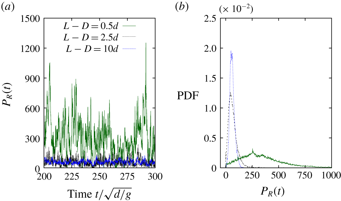
Figure 8 shows the fluctuation of  $P_{R}(t)$ with time
 $t$. There are distinct peaks that characterize the maximum buildup of stress in the force chains. Additionally, there are times when the pressure is very low. We consider a threshold pressure
 $P_{th}$ which is analogous to the threshold stress in the calculation of force chains. If
 $P_{R}(t)$ goes below
 $P_{th}$ in the region
 $R$, then the grains in
 $R$ do not satisfy the criteria to form force chains. This can effectively help us quantify the buildup and buckling of force chains. We propose two quantities:
 $P_{fc}$ and
 ${\mathcal{P}}(P_{R}(t)<P_{th})$. The first term
 $P_{fc}$ is the average
 $P_{R}(t)$ when
 $P_{R}(t)\geqslant P_{th}$, and the second term
 ${\mathcal{P}}(P_{R}(t)<P_{th})$ is the probability that
 $P_{R}(t)<P_{th}$.
 $P_{fc}$ can effectively characterize the average strength while
 ${\mathcal{P}}(P_{R}(t)<P_{th})$ can help characterize the rate of buckling of force chains. We take
 $P_{th}$ as the global average in the plane
 $z=0$ which is very close to the value of
 $(\unicode[STIX]{x1D70C}dg\times P_{head})$, and therefore, we approximate
 $P_{th}\approx \unicode[STIX]{x1D70C}dgP_{head}$.
(a) The fluctuation in  $P_{R}(t)$ with time (for better clarity a given span of time has been displayed but the behaviour is identical in any span we choose) for
 $V=1.0\sqrt{dg}$,
 $\unicode[STIX]{x1D707}=0.5$, and
 $P_{head}=47.7$. (b) The probability density function (PDF) of the
 $P_{R}(t)$ fluctuations. The symbols mean the same as in (a).

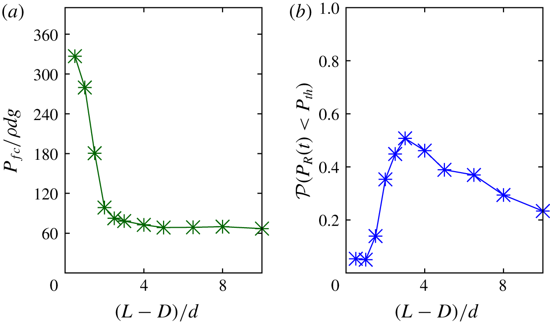
Plots showing (a)  $P_{fc}$ which is the average
 $P_{R}(t)$ when
 $P_{R}(t)\geqslant P_{th}$ and (b)
 ${\mathcal{P}}(P_{R}(t)<P_{th})$, i.e., the probability that
 $P_{R}(t)<P_{th}$ versus
 $L-D$ at
 $V=1.0\sqrt{dg}$,
 $\unicode[STIX]{x1D707}=0.5$ and
 $P_{head}=47.7$.

In figure 9(a,b), the variation of  $P_{fc}$ and
 ${\mathcal{P}}(P_{R}(t)<P_{th})$, respectively, with
 $L-D$ has been shown for the case of
 $P_{head}=47.7$,
 $\unicode[STIX]{x1D707}=0.5$ and
 $V=1.0\sqrt{dg}$. When the intruders are very close to each other, i.e. at lower
 $L-D$, the force chains use the surface of the other intruder to stabilize themselves. This phenomenon is the leverage that force chains use against buckling to stabilize themselves and has been discussed in a few studies (Butlanska et al. Reference Butlanska, Arroyo, Gens and OSullivan2014; Tordesillas et al. Reference Tordesillas, Hilton and Tobin2014). However, as
 $L-D$ increases, the surface of the other intruder moves far away, thus decreasing this stabilization and increasing this buckling. We can see that, in figure 9(a),
 $P_{fc}$ decreases until it reaches an almost constant value. This constant value is achieved when the surface of the second intruder is far enough not to allow the stabilization of force chains due to its surface.
It is necessary to consider  ${\mathcal{P}}(P_{R}(t)<P_{th})$ that can help in characterizing the buckling of the force chains. If
 ${\mathcal{P}}(P_{R}(t)<P_{th})$ is low, then this would imply that the force chains are more stable. Figure 9(b) shows
 ${\mathcal{P}}(P_{R}(t)<P_{th})$ versus
 $L-D$, where we observe that the force chains are initially stable at very low
 $L-D$ due to the support from the second intruder. However, they lose their stability as a consequence of losing their leverage against buckling and lying in the shear zone of the other intruder. This only happens until a certain
 $L-D$ beyond which the force chains start to become stable as they withdraw out of the shear zone of the other intruder. In simpler terms, a force chain projecting from one intruder may get buckled by many factors such as the surface or the shear zone of the second intruder. The surface tends to stabilize the force chain while the shear zone of the other intruder tends to buckle the force chain. However, after a certain
 $L-D$, the force chains lie outside the shear zone of the other intruder. This, in turn, stabilizes the force chains. However, it is vital to notice that even though the force chains become stable, they cannot build a pressure higher than at low
 $L-D$ due to lack of support (surface of the second intruder). Since the above two effects counteract each other, the attraction reaches a maximum and then decreases.
3.5 Mean flow fields
In this subsection, we have presented the mean flow field around the intruders moving at  $V=1.0\sqrt{dg}$,
 $\unicode[STIX]{x1D707}=0.5$ and
 $P_{head}=47.7$. We have taken the
 $z=0$ plane for our visualization and calculated the flow field parameters by coarse graining, as used in the previous subsection. We have considered the flow field quantities such as granular temperature
 $T$, velocity magnitude
 $v$, pressure
 $P$ and volume fraction
 $\unicode[STIX]{x1D6F7}$. By comparing the differences in the flow fields for various
 $L-D$, we can gain insights into the sideways arrangement of intruders.
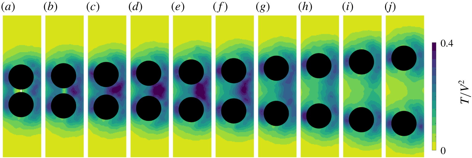
The granular temperature  $T$ (shown in the
 $xy$ plane) normalized by the square of the intruder velocity
 $V$ for
 $(L-D)/d=$ (a) 0.5, (b) 1.0, (c) 1.5, (d) 2.0, (e) 2.5, (f) 3.0, (g) 4.0, (h) 5.0, (i) 6.5 and (j) 8.0 averaged over 8000 frames during the entire simulation run after mean steady-state behaviour was achieved at
 $V=1.0\sqrt{dg}$,
 $\unicode[STIX]{x1D707}=0.5$ and
 $P_{head}=47.7$. Refer to figure 1 for the direction of the intruders.

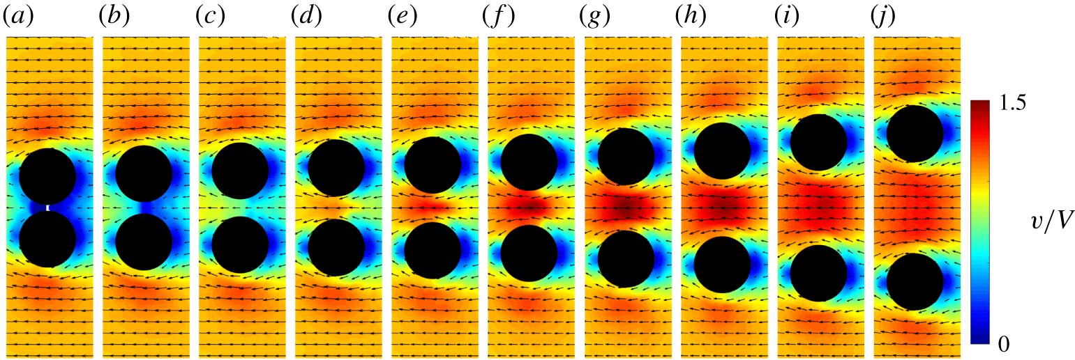
The velocity magnitude  $v$ with respect to the intruder frame (shown in the
 $xy$ plane) normalized by the intruder velocity
 $V$ for
 $(L-D)/d=$ (a) 0.5, (b) 1.0, (c) 1.5, (d) 2.0, (e) 2.5, (f) 3.0, (g) 4.0, (h) 5.0, (i) 6.5 and (j) 8.0 averaged over approximately 8000 frames during the entire simulation run after mean steady-state behaviour was achieved at
 $V=1.0\sqrt{dg}$,
 $\unicode[STIX]{x1D707}=0.5$ and
 $P_{head}=47.7$. Refer to figure 1 for the direction of the intruders.

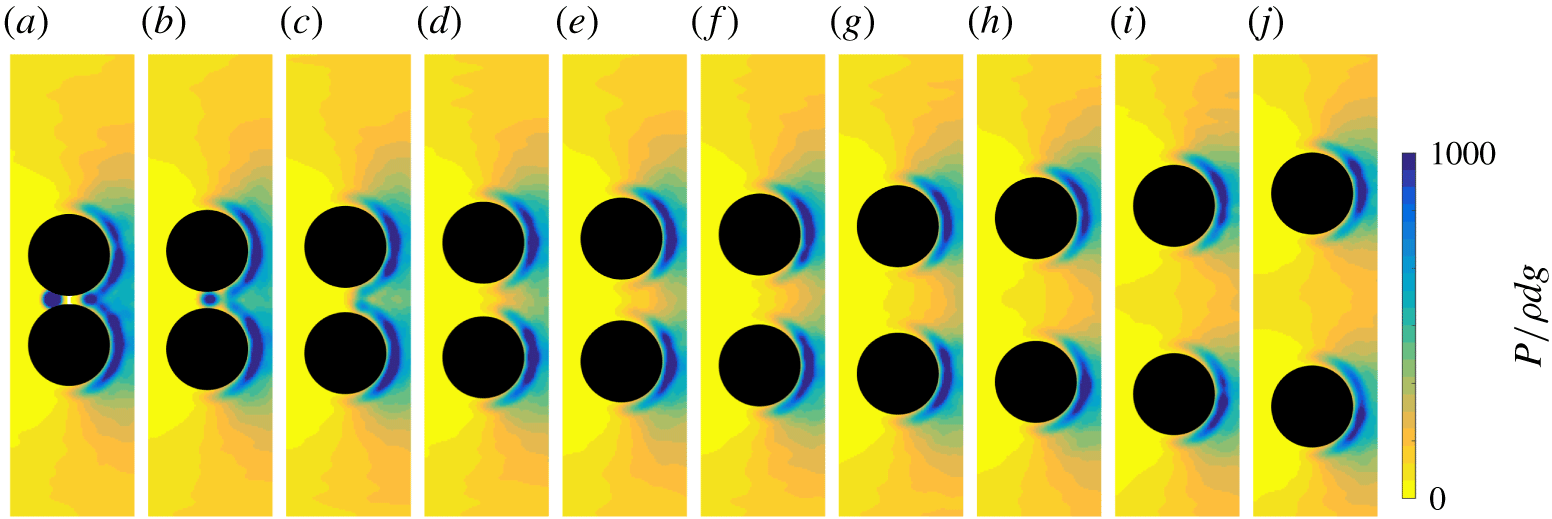
The pressure  $P$ (shown in
 $xy$ plane) at a given point normalized by
 $\unicode[STIX]{x1D70C}dg$ for
 $(L-D)/d=$ (a) 0.5, (b) 1.0, (c) 1.5, (d) 2.0, (e) 2.5, (f) 3.0, (g) 4.0, (h) 5.0, (i) 6.5 and (j) 8.0 averaged over approximately 8000 frames during the entire simulation run after mean steady-state behaviour was achieved at
 $V=1.0\sqrt{dg}$,
 $\unicode[STIX]{x1D707}=0.5$ and
 $P_{head}=47.7$. Refer to figure 1 for the direction of the intruders.

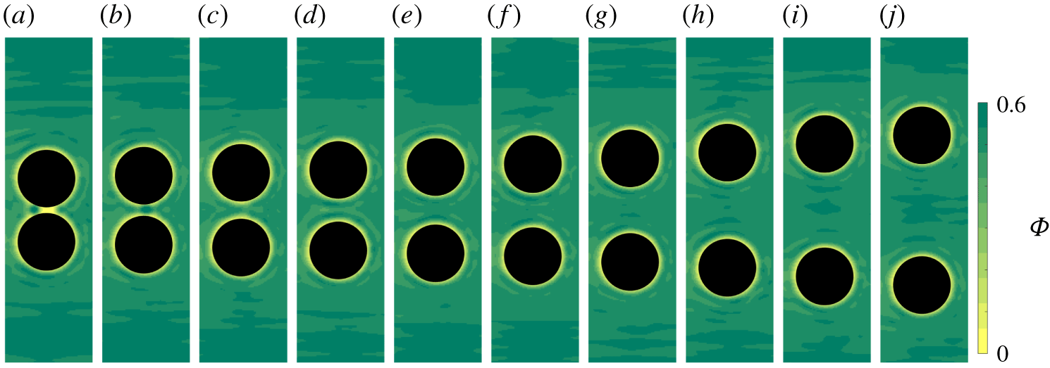
The volume fraction  $\unicode[STIX]{x1D6F7}$ (shown in the
 $xy$ plane) for
 $(L-D)/d=$ (a) 0.5, (b) 1.0, (c) 1.5, (d) 2.0, (e) 2.5, (f) 3.0, (g) 4.0, (h) 5.0, (i) 6.5 and (j) 8.0 averaged over approximately 8000 frames during the entire simulation run after mean steady-state behaviour was achieved at
 $V=1.0\sqrt{dg}$,
 $\unicode[STIX]{x1D707}=0.5$ and
 $P_{head}=47.7$. Refer to figure 1 for the direction of the intruders.

In figure 10, we have shown the granular temperature field near the intruder for various  $L-D$. If one were to recall hemispheres A and B from previous subsections, A is the side facing the other intruder while B is the other half. The granular temperature around the hemisphere B does not seem to change much as
 $L-D$ increases. However, the granular temperature around the hemisphere A and in the gap between the intruders varies with
 $L-D$. We know that the probability of buckling of force chains
 ${\mathcal{P}}(P_{R}(t)<P_{th})$ first increases, and then decreases (see figure 9b). When the buckling occurs, the grains in the force chain tend to move randomly and thus increase the granular temperature (Tordesillas et al. Reference Tordesillas, Hilton and Tobin2014). We can observe that the granular temperature in the gap and around hemisphere A increases until approximately the same
 $L-D$ until which
 ${\mathcal{P}}(P_{R}(t)<P_{th})$ increases, i.e. until the point the attractive force between the intruders increases. However, after this certain
 $L-D$, the buckling starts to decrease, leading to the lowering of granular temperature.
In figure 11, we present the velocity field near the intruders for various  $L-D$. There exists a high velocity region at the centre of the line joining the intruders, and similar to the case of granular temperature, we observe that the velocity first increases, and then decreases. However, a very interesting and intriguing observation is that the velocity of the grains in the gap exceeds the flow velocity. This is because the force chains store and accumulate strain energy along the contact points which is then released in the form of kinetic energy during the buckling (Walker, Tordesillas & Froyland Reference Walker, Tordesillas and Froyland2014). This burst in kinetic energy increases the velocity of the grains (as well as the granular temperature). Once the rate of buckling decreases after a certain
 $L-D$, the burst in the kinetic energy also decreases.
In figure 12, the pressure field is shown. The pressure around the intruder is not symmetric, which results in a net sideways force. This has earlier been captured in the pressure distribution plots. Additionally, it can be seen that Bernoulli’s principle does not work well for granular media since the  $P$ and
 $v$ flow fields are vastly different from each other. In figure 13, we can see that the volume fraction is more or less constant. Since this is a gravitational system, the low volume fraction region is immediately filled by the grains.
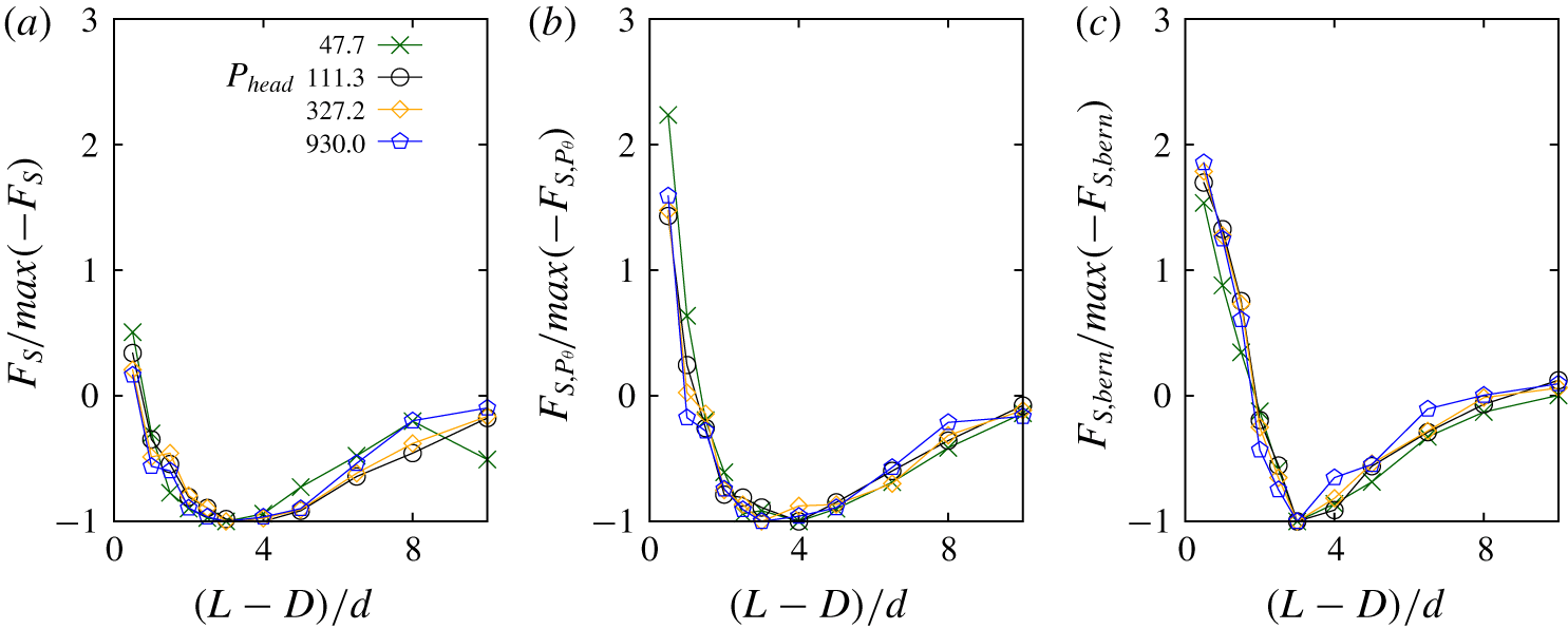
Plots showing (a) sideways force  $F_{S}$, (b) sideways force
 $F_{S,P_{\unicode[STIX]{x1D703}}}$ from integration of
 $P_{\unicode[STIX]{x1D703}}$ and (c) sideways force
 $F_{S,bern}$ from Bernoulli’s principle normalized by the maximum attraction in each case versus the space between the two intruders
 $L-D$ moving at a friction coefficient
 $\unicode[STIX]{x1D707}=0.5$ for various pressure heads
 $P_{head}$. The symbols mean the same as in (a).

3.6 Model
In this subsection, we propose an approximate model that can help predict the trends of  $F_{S}$ versus
 $L-D$ qualitatively. In order to do so, we will integrate Bernoulli’s principle with the minimum contact criterion for force chains. We know that the contacts with force chains apply a much larger pressure on the intruder in comparison to the contacts that do not form a force chain network. Therefore, we apply the following model to calculate the estimated pressure
 $P_{m}$ at a point
 $K$ for some constant
 $c$:
 $$\begin{eqnarray}P_{m}=\left\{\begin{array}{@{}ll@{}}c(V^{2}-v^{2}),\quad & \text{for }N\geqslant 2,\\ 0,\quad & \text{for }N<2.\end{array}\right.\end{eqnarray}$$
Although the strength of force chains varies with  $\unicode[STIX]{x1D703}$ (Tordesillas et al. Reference Tordesillas, Hilton and Tobin2014), this simple adjustment allows us to generate plots of
 $P_{m}$ with
 $\unicode[STIX]{x1D703}$ that are very similar to the
 $P_{\unicode[STIX]{x1D703}}$ distribution plots. We, in our future studies, will try to amalgamate the strength of the force chains with Bernoulli’s equation.
If we were to estimate the sideways force due to pressure  $F_{S,P_{\unicode[STIX]{x1D703}}}$ from pressure
 $P_{\unicode[STIX]{x1D703}}$ alone and not the shear stress, then,
 $F_{S,P_{\unicode[STIX]{x1D703}}}=\int P_{\unicode[STIX]{x1D703}}\cos \unicode[STIX]{x1D703}\,\text{d}(D/2)\,\text{d}\unicode[STIX]{x1D703}$. In figure 14(a,b), we have plotted the sideways force
 $F_{S}$ and estimated sideways force
 $F_{S,P_{\unicode[STIX]{x1D703}}}$, respectively, normalized by their corresponding maximum attraction versus
 $L-D$. The two plots are quite similar, except near the repulsion regime due to several factors such as only integrating in the
 $z=0$ plane instead of the entire intruder, and not considering the effect of shear stress. However, the objective of comparing the two results is to show that the trend of sideways force can be well captured by the pressure distribution alone. Moreover, in the experiments, it is much easier to determine the velocities of grains compared to the stress acting on them. Therefore, if we can relate the velocities to this pressure
 $P_{\unicode[STIX]{x1D703}}$, then the velocities also can be used to predict the trends of sideways force in real life scenarios.
In figure 14(c), we have plotted the estimated sideways force from the modified Bernoulli’s equation (3.9) ( $F_{S,bern}=\int P_{m}\cos \unicode[STIX]{x1D703}\,\text{d}(D/2)\,\text{d}\unicode[STIX]{x1D703}$) normalized by the maximum attraction versus
 $L-D$. Figures 14(a) and 14(b) are very similar, suggesting that our minimum contact criterion combined with Bernoulli’s equation is in agreement with the pressure. This can be used in the future experiments to predict the sideways force without actually measuring the pressure. The assumptions made by Cruz & Caballero-Robledo (Reference de la Cruz and Caballero-Robledo2016) do not justify the claim of invalidating the explanations based on Bernoulli’s equation, such as those used by Zuriguel et al. (Reference Zuriguel, Boudet, Amarouchene and Kellay2005a), since there is no proper evidence that regions defined at
 $\unicode[STIX]{x1D703}=\unicode[STIX]{x03C0}/4$ and
 $3\unicode[STIX]{x03C0}/4$ can capture the entire pressure distribution. On the other hand, the explanation used by Zuriguel et al. (Reference Zuriguel, Boudet, Amarouchene and Kellay2005a) does a good job of guessing the direction of the sideways force but cannot predict the qualitative trend as our model can. However, this model cannot be used as an origin to explain the forces but is merely a mathematical adjustment. The origin has been explained in § 3.4.
A non-local granular fluidity model, as explained in Kamrin & Henann (Reference Kamrin and Henann2015), Zhang & Kamrin (Reference Zhang and Kamrin2017) and Liu & Henann (Reference Liu and Henann2018), to capture the width of the repulsive zones in our study will be an important future problem.
4 Conclusion
We have numerically studied a system consisting of two intruders placed side by side in a granular medium with the help of the discrete element method. The origin of the long-ranged forces between the intruders has been a matter of debate (Aumaître et al. Reference Aumaître, Kruelle and Rehberg2001; Sanders et al. Reference Sanders, Swift, Bowley and King2004; Zuriguel et al. Reference Zuriguel, Boudet, Amarouchene and Kellay2005a; Pacheco-Vázquez & Ruiz-Suárez Reference Pacheco-Vázquez and Ruiz-Suárez2010; Cruz & Caballero-Robledo Reference de la Cruz and Caballero-Robledo2016), and in this work, the origin of such long-ranged forces has been delineated with the concept of force chain evolution and buckling. Our proposed origin is also supported by the flow fields in the vicinity of the intruders, and incorporating the flow field parameters such as pressure and velocity seems to predict the trend of sideways force with the separation distance qualitatively. The strength of these forces has been investigated for various separation lengths  $L-D$, coefficients of friction
 $\unicode[STIX]{x1D707}$, pressure heads
 $P_{head}$ and velocities
 $V$ of the intruder.
4.1 Sideways force, drag and number of contacts
The sideways force  $F_{S}$ seems to be almost zero for a single intruder system, but in the presence of a second intruder, a finite sideways force whose magnitude depends on the separation distance
 $L-D$ is observed. At lower separation distances, the sideways force is repulsive, but at higher separation distances, it is attractive. The transition between repulsive and attractive separation distance goes through an equilibrium point where the sideways force becomes zero. The drag
 $F_{D}$ and the number of contacts
 $N_{c}$ seem to be almost constant with the separation distance; however, the drag is lower for the two intruder system compared to its single counterpart.
4.2 Angular distribution of quantities around the intruder
The distribution of pressure around the intruder matches neither with that of the velocity nor with the granular temperature, indicating that the earlier hypothesis relating the velocity or the granular temperature is not necessarily valid. The primary reason for such is that the effect of force chains is not integrated; for example, a spike in granular temperature can be due to buckling of force chains. Additionally, the volume fraction remains constant, indicating that volume fraction cannot be responsible for these sideways forces.
4.3 Origin of sideways force
The force chains extend to several grain diameters from the intruder surface. The force chains extending laterally from an intruder are stabilized by the surface of the second intruder, while the shear zone of the second intruder tends to destabilize the force chains. This creates an imbalance in the pressure around the intruder, resulting in a net sideways force. We have presented evidence to support this in terms of the pressure fluctuation, the mean force chain strength and the probability of the pressure being lower than a threshold.
4.4 Mean flow fields
The pressure field around each intruder is seen to be asymmetric, which explains the net sideways force. The buckling of force chains can explain the granular temperature field behaviour; it makes the grains in the force chains move in random directions, thus increasing the granular temperature. The granular temperature increases in the gap between the intruders until buckling probability increases and vice versa. The velocity field shows that there are points where the velocity can exceed the flow velocity, which again is due to the release of kinetic energy during buckling. The volume fraction field is almost constant.
4.5 Model
The model incorporates a minimum contact criterion of the force chain with Bernoulli’s equation, providing us with the qualitative trend of sideways force with the separation distance.
4.6 Implications for future work
Questions such as (i) how an attractive sideways force approaches zero, (ii) the effect of grain shape on the cross-over between repulsive and attractive regime, (iii) the existence of any effect of rotation of intruder on the sideways force, (iv) whether a modified Bernoulli’s principle explains the trends of sideways force and (v) whether non-local continuum models predict the width of the repulsive zones, will be interesting future work in our opinion.
Acknowledgements
We thank PARAM-ISHAN, the supercomputing facility at IITG. M.D. thanks MHRD, Government of India, for providing financial assistance during the completion of this work.