Introduction
Plastic has been one of the most widely used synthetic polymers in a range of applications from food containers to space suits, with attracting features of flexibility, light weight, and low cost [Reference Wang, Wang, Gu, Lin, Zhang, Huang and Zhao1, Reference Zhang, Liu, Zhao, Cheng, Zhang, Wu, Wang, Dai, Zhang, Ding, Wu and Liu2, Reference Zhang, Chen, Luo, Zhao, Luo, Xiang, Wang, Wang, Yang, Zhu and Liu3, Reference Kwon, Koizumi, Chung, Kodera, Kim and Saido4, Reference Zheng, Wu, Chen, Cheng, Zhang, Xie, Wang, Zhang, Wang, Peng and Zeng5]. However, pollution caused by plastics is a worrying issue. About 15–20% of waste plastics can be recycled by conventional recycling techniques, such as sorting, grinding, washing, and extrusion, but the vast majority end up as trash [Reference Miandad, Barakat, Aburiazaiza, Rehan, Ismail and Nizami6, Reference Miandad, Nizami, Rehan, Barakat, Khan, Mustafa, Ismail and Murphy7]. The discarded plastics are problematic in natural environment because they exist in some form for a long time. Polystyrene (PS) is one of the most widely used plastic and does not biodegrade for hundreds of years [Reference Kwon, Koizumi, Chung, Kodera, Kim and Saido4, Reference Miandad, Barakat, Aburiazaiza, Rehan, Ismail and Nizami6, Reference Miandad, Nizami, Rehan, Barakat, Khan, Mustafa, Ismail and Murphy7, Reference Fu, Ding, Tang, Li, Zhao, Chen, Zhang, Fu, Long and Tan8, Reference Miandad, Rehan, Nizami, Barakat, Ismail, Karthikeyan, Heimann and Muthu9]. It is a formidable task to recycle and dispose PS products. Actually, most PS products are not currently recycled because of lack of economic benefits. On the other hand, as an aromatic hydrocarbon, PS is a potential carbon source. Exploratory research has been done in many groups. Xu and colleagues used styrene as a carbon precursor to prepare hollow monodisperse carbon nanospheres after cross-linking of styrene and carbonization [Reference Li, Chen, Xu, He and Chen10]. Hollow spherical sludge carbons were prepared by pyrolyzing PS wastes covered with sewage sludge [Reference Wu, Kong, Hu, Tian and Xiong11]. Our group has reported a “dissolution–capture” method to synthesize hollow mesoporous carbon spheres using PS as the carbon source [Reference Chen, Li, Yu, Li, Xia, Wang, Li and Zhang12]. Cross-linking reactions occur during the synthesis processes to gain a high carbon yield. However, organic solvents and catalysts are required for successful synthesis, and the morphology and structure of the hollow carbon spheres are not always satisfactory.
The ordered mesoporous carbons (OMCs) with high surface area, large pore volume, uniform pore size, good mass transfer channels, and a large number of potential active sites are widely used in various applications such as energy storage, catalysis, adsorption, and supercapacitors because of their favorable structures [Reference Chen, Li, Yu, Li, Xia, Wang, Li and Zhang12, Reference Shi, Zhang, Lv, Deng, Elzatahrya and Zhao13, Reference You, Liao, Qiao, Zeng, Liu, Zheng, Song, Zeng and Li14, Reference Zheng, Wang, Liang, Zhu, Wu and Ouyang15, Reference Goscianska, Marciniak and Pietrzak16]. They are an ideal alternative to traditional porous activated carbon as a potential electrode material for supercapacitors in electronic devices. Uniformly ordered channels shorten the diffusion distance of ions and accelerate the diffusion of electrolytes. The presence of mesopores accelerates the kinetics of ions in the electrode, reduces pore blockage, and improves power performance at high current densities [Reference Zhai, Dou, Zhao, Fulvio, Mayes and Dai17, Reference Zhou, Bao, Wu, Yang and Wang18, Reference Zhang and Zhao19]. Commonly, OMCs are synthesized by template method, which includes hard template and soft template approaches [Reference Lim, Jo and Lee20, Reference Luo, Zhao, Li, Wei, Xu, Li, Wang, Zhang, Elzatahry, Alghamdi, Deng, Wang, Jiang, Liu, Kong and Zhao21]. Soft template methods are based on the co-self-assembly of carbon precursors and decomposable amphiphilic molecules. However, the mesoporous structures of carbon materials are usually disordered due to the deformability of the soft template [Reference Li, Pasc, Fierro and Celzard22]. Hard template methods typically use materials having a mesoporous structure (e.g., mesoporous silica) as templates, which provide a rigid skeleton for the controlled fabrication of ordered structures and do not require careful hydrolysis and polycondensation of the precursors under rigorous conditions, compared with soft template method [Reference Lim, Jo and Lee20, Reference Chu, Wang, Chi, Wang, Lei, Zhang and Yang23, Reference Wang, Wang, Liu, Zhang, Du, Zhang, Liu, Liang and Chen24]. After filling into the mesochannels of the hard template through liquid phase immersion or chemical vapor deposition (CVD) processes, carbon precursors are subjected to high temperature to achieve carbonization [Reference Xia and Mokaya25, Reference Liu, Zhang, Wang, Du, Zhang, Fu and Chen26]. By employing CVD method, gaseous carbon precursors, such as methane and ethylene, can be transformed into carbon matrix on pre-prepared template under catalysis of transition metals (e.g., Fe, Co, Ni) [Reference Gong, Liu, Che, Wen, Jiang, Mijowska, Wang and Tang27, Reference Maetz, Delmotte, Moussa, Denzer, Knopf and Ghimbeu28, Reference Liu, Li, Song, Liu, Yu and Ge29, Reference Zheng, Zao, Zhang, Cheng, Chen, Zhang, Wang and Peng30]. Mokaya has prepared porous graphitic carbon materials via CVD method using various mesoporous silicas as hard templates and acetonitrile as a carbon precursor [Reference Xia and Mokaya25]. Vinu’s group used benzene deposition on Fe-SBA-15 by CVD method to obtain carbon nanotubes [Reference Suryavanshi, Baskar, Balasubramanian, Al-Deyab, Al-Enizi and Vinu31]. However, the specific CVD equipment used in these reported experiments to synthesize carbon materials is relatively cumbersome. The conventional CVD method requires a plurality of steps, which is somewhat time consuming and complicated and may cause problems such as pore blocking and disordered pore arrangement [Reference Huang, Wang, Wei and Huang32, Reference Mane, Talapaneni, Anand, Varghese, Iwai, Ji, Ariga, Mori and Vinu33]. Huang et al. used para-toluene sulfonic acid (PTSA)-modified SBA-15 as a template to prepare nitrogen-doped OMC by pyrolysis method, but the preparation work in the early stage mostly used organic solvent, vacuum filtration, and high temperature reflux [Reference Huang, Wang, Wei and Huang32]. These steps are cumbersome and the requirements are relatively high. Therefore, it is highly desirable to develop a simple method for directly reusing exhaust gas as a carbon precursor to synthesize mesoporous carbon materials.
Using the CVD strategy as reference, we propose a new method for the preparation of OMCs via a “pyrolysis–deposition” strategy. Compared with the previously reported synthesis process using conventional CVD method, the pyrolysis–deposition synthesis process is simply accomplished in one tube furnace rather than in relatively complex CVD equipment. Waste PS is used to provide the carbon source, which is generated in situ by pyrolysis of PS under high temperature, SBA-15 serves as the hard template, and Fe(NO3)3 serves as catalyst. Fe-modified SBA-15 and PS are mixed and in the tube furnace for pyrolyzation. During the pyrolysis process, PS decomposes into small organic gases, which are adsorbed into the mesochannels of Fe-SBA-15 by capillary action and deposited and then converted into carbon–silica composites. After etching of silica and Fe, the OMCs replicating the morphology of SBA-15 were obtained. We also optimized synthesis conditions by adjusting the mass ratio of PS/Fe-SBA-15 and pyrolysis temperature. The prepared OMCs have an ordered mesoporous structure with high surface area and good performance as the electrode materials. This work not only avoids the use of large amounts of solvent but also provides the unique opportunity and a facile method for reusing waste PS or other waste plastics to prepare carbon materials, so that the waste energy will be reused and the exhaust gas emission will be reduced.
Results and discussion
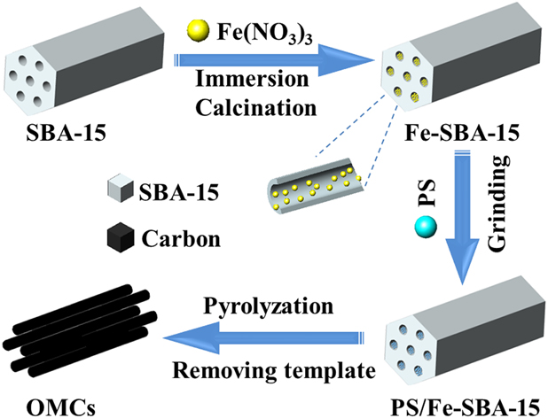
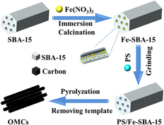
Figure 1 illustrates the detailed formation process of OMCs. First, Fe(NO3)3 is impregnated into the channels of SBA-15 at room temperature. In this process, Fe ions will react with Si–OH groups of SBA-15 to form Fe–O–Si and Fe-SBA-15 after drying and calcination. The composite PS/Fe-SBA-15 was obtained by simple mechanical mixing of Fe-SBA-15 and PS without removing Fe. At high temperatures, PS is pyrolyzed into carbonaceous gases, including methane and ethylene [Reference Gong, Liu, Che, Wen, Jiang, Mijowska, Wang and Tang27], and these small molecules are adsorbed into the channels of Fe-SBA-15 and deposited in the pores of the template under the catalysis of Fe. Then, a pyrolysis process occurs in a tube furnace to convert the carbonaceous gas into carbon matrix. After etching of the silica and Fe, OMCs are obtained. It is noteworthy that under similar pyrolysis conditions, the carbon material cannot be obtained when the mixture of pure SBA-15 and PS is pyrolyzed. This result indicated the key role of Fe-based catalyst in the formation of carbon materials.
Illustration for the fabrication of the OMCs based on pyrolytic deposition strategy.

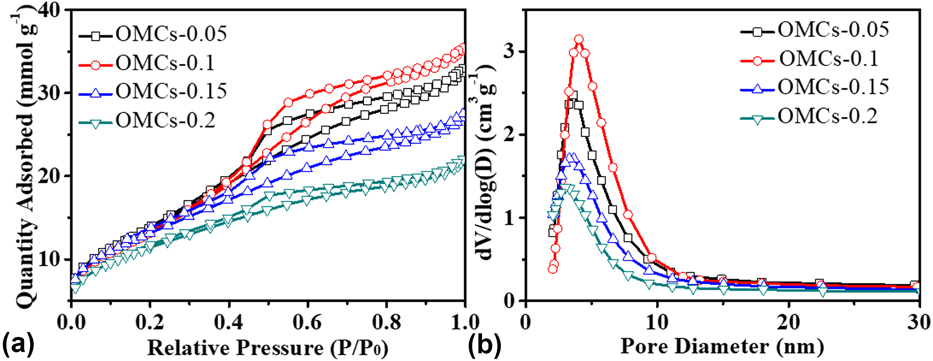
Considering the effect of Fe(NO3)3 amount on surface area, pore volume, and pore size of OMCs, different amount of Fe(NO3)3 (0.05–0.2 g) is applied to synthesize OMCs, whereas mass ratio of PS/Fe-SBA-15 is remained at 1 and pyrolysis temperature is 800 °C. The N2 adsorption–desorption isotherms of these OMCs with different amounts of Fe(NO3)3 exhibit typical type-IV curves hysteresis in the relative pressure range of 0.45–0.8 P/P 0, which indicates the presence of mesoporous structure [Reference Martín, Morales, Martínez, Grieken, Cao and Kruk36]. As shown in Fig. 2(a), with the increase in Fe(NO3)3 from 0.05 to 0.2 g, the Brunauer–Emmett–Teller (BET) surface area of OMCs decreased from 1156 to 916 m2/g and the pore volume decreased from 1.23 to 0.76 cm3/g. The decreased surface area and pore volume may be due to the existence of Fe(NO3)3 in the mesochannels of SBA-15, which impedes penetration of carbon precursor into the channels. The corresponding pore size distribution curves of OMCs with different amounts of Fe(NO3)3 are shown in Fig. 2(b). All samples show a uniform pore size distribution between 3.5 and 4.0 nm, close to the wall thickness (4.0 nm) of the SBA-15 template, indicating that the mesoporous structures are formed by the removal of the template.
(a) The nitrogen adsorption–desorption isotherms, and (b) the pore size distribution of OMCs (PS/Fe-SBA-15 = 1) with different amounts of Fe(NO3)3 from 0.05 to 0.2 g.

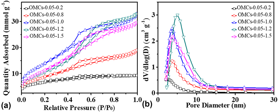
We also examined the effect of mass ratio of PS/Fe-SBA-15 on the structural parameters of OMCs. At temperature of 800 °C, the N2 adsorption–desorption isotherm of OMCs-0.05 with different PS/Fe-SBA-15 ration exhibit typical type-IV curves hysteresis in the relative pressure range of 0.45–0.8 P/P 0, which indicates the presence of mesoporous structure [Fig. 3(a)]. With the increase in PS/Fe-SBA-15 mass ratio from 0.2 to 1, the BET surface area increases from 500 to 1156 m2/g and pore volume increases from 0.32 to 1.23 cm3/g. However, with higher PS/Fe-SBA-15 mass ratio above 1, the BET surface area and pore volume decrease conversely, indicating the effect of mass ratio of PS/Fe-SBA-15 on the specific surface area and pore volume of OMCs. When PS/Fe-SBA-15 = 0.2, the BET of OMCs-0.05-0.2 is very small (only 500 m2/g), which indicates that very few pyrolyzed gases generated from PS and the gases cannot sufficiently fill the pores of the template, leading to pore collapse during the etching of template silica. However, when the mass ratio of PS/Fe-SBA-15 is too large, the pyrolysis gas cannot be effectively deposited in the SBA-15 pores, resulting in a decrease in surface area and a waste of PS. When the mass ratio of PS/Fe-SBA-15 is 1, OMCs show the largest BET surface area of 1156 m2/g. Meanwhile, these OMCs show pore sizes distribution centered at about 3.7 nm [Fig. 3(b)].
(a) The N2 adsorption–desorption isotherms, and (b) the pore size distribution of OMCs-0.05 with different amounts of PS.

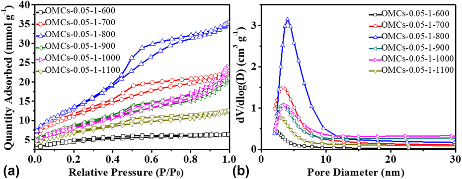
The pyrolysis temperature also affects the structural parameters of carbon materials. So N2 adsorption–desorption isotherms of OMCs-0.05-1 at different pyrolysis temperatures are investigated. As shown in Fig. 4(a), the OMCs-0.05-1-600 had little hysteresis loops, suggesting that poor mesoporous structure was formed under this temperature. Other N2 adsorption–desorption isotherms of OMCs-0.05-1 under higher temperatures between 700 and 1100 °C exhibit typical type-IV curves hysteresis in the relative pressure range of 0.45–0.8 P/P 0, which indicates the presence of mesoporous structure. Both the specific surface area and the pore volume of the OMCs change with increasing pyrolysis temperature. When the temperature increased from 600 to 800 °C, the specific surface area of OMCs increased from 346 to 1156 m2/g and the pore volume increased from 0.22 to 1.23 cm3/g. However, under much higher temperature, both the specific surface area and the pore volume decreased gradually. When the temperature reached 1100 °C, the specific surface area and the pore volume decreased to 537 m2/g and 0.44 cm3/g, respectively. The reason may be that the products of PS pyrolysis cannot be effectively deposited in the mesoporous of SBA-15 at low pyrolysis temperatures, and higher pyrolysis temperature leads to collapse of the pores in OMCs. The corresponding pore size distribution curves of OMCs-0.05-1 at different pyrolysis temperatures are shown in Fig. 4(b). The detailed structural parameters of all OMCs samples are listed in Table I.
(a) The nitrogen adsorption–desorption isotherms, and (b) the pore size distribution of OMCs-0.05-1 at different pyrolysis temperatures.

The structural parameters of OMCs.

S BET: Specific surface area from multiple BET (Brunauer–Emmett–Teller) method; V t: Total pore volume at P/P 0 = 0.97; Dme: Pore size distribution calculated by using the BJH model.
The OMC-0.05-1-800 was chosen for further investigation due to its larger surface area and more uniform pore size distribution. The small-angle XRD pattern of OMCs-0.05-1-800 is shown in Fig. 5(a). The OMC-0.05-1-800 displays an obvious well-resolved diffraction peaks at 0.92° and a bulge at 1.7° indexed as (100) and (110) reflections associated with 2D hexagonal p6mm, indicating an ordered mesophases [Reference Wan, Liu, Li, Xue and Liang37, Reference Martins, Cunha, Oliveira and Moura38]. The intense (100) scattering peak reflects a d-spacing of 9.6 nm, which corresponds to a unit-cell parameter of 11.1 nm. The wide-angle XRD pattern of the OMCs-0.05-1-800 is shown in Fig. 5(b). Two weak diffraction peaks are observed at 24.5° and 43.6°, indicating that OMC-0.05-1-800 mainly consists of amorphous carbon [Reference Cakiryilmaz, Arbag, Oktar, Dogu and Dogu39].
(a) The small-angle X-ray diffraction (XRD), and (b) wide-angle XRD patterns of OMCs-0.05-1-800.

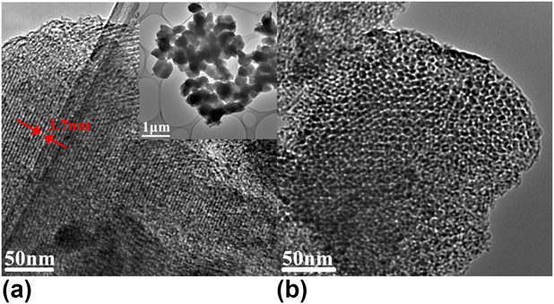
The detailed morphology and porous structure of the OMCs-0.05-1-800 are investigated by transmission electron microscopy (TEM). The inset of Fig. 6(a) shows that the obtained OMC-0.05-1-800 exhibits a rod-like morphology, which means a faithful replication of morphology of SBA-15. Figure 6(a) shows one-dimensional channel and strip-like porous precipitates. The mesoporous structure of OMCs with uniform pore size of 3.7 nm could be seen from the TEM images [the red arrows in Fig. 6(a)]. The TEM image in vertical pore orientation [Fig. 6(b)] shows an ordered array of hexagonal mesoporous, further indicating the 2D hexagonal mesostructure preserved after the pyrolysis process.
(a, b) TEM of the OMCs-0.05-1-800.

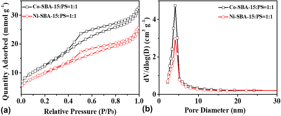
Furthermore, SBA-15 modified by other metal catalysts [Co(NO3)2·6H2O, Ni(NO3)2·6H2O] are also used as templates for the preparation of OMCs. The N2 adsorption–desorption isotherms of OMCs with different metal catalysts showed typical type-IV hysteresis curves in the relative pressure range of 0.45–0.8 P/P 0. The specific surfaces areas of the two samples are 1048 and 821 m2/g, respectively, and the pore volume of the two samples are 1.12 and 0.89 cm3/g, respectively. Compared with the two, the use of Fe as the catalyst under the same conditions gives a higher specific surface area and a larger pore volume, which has a positive effect on the OMCs-0.05-1-800 as an electrode material. As shown in Fig. 7(b), there is a uniform pore size distribution at 4.0 nm, indicating that both have the uniform mesoporous structure.
(a) The N2 adsorption–desorption isotherms, and (b) the pore size distribution of OMCs with different metal catalysts.

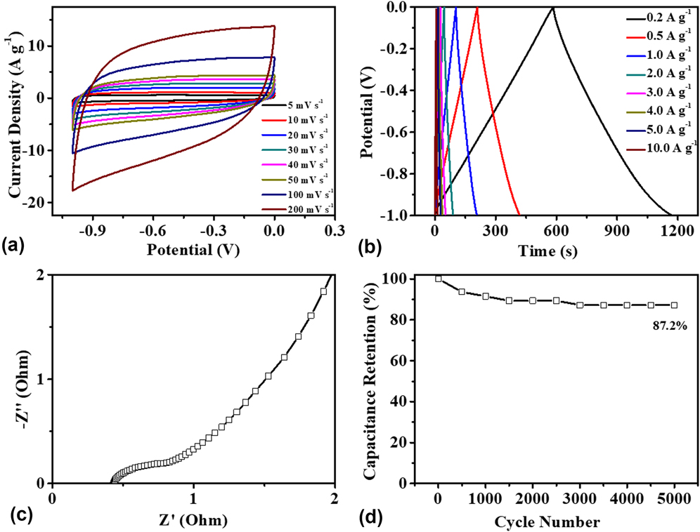
Supercapacitors are considered to be excellent candidates for energy storage devices and have been widely used in hybrid vehicles. Porous carbon materials with high surface area, good electronic conductivity, and superior chemical stability are great electrode materials for supercapacitors [Reference Cakici, Reddy and Alonso-Marroquin40, Reference Rose, Prasad, Sakthivel, Gunasekaran, Maiyalagan and Vijayakumar41, Reference Liu, Zhou, Zhao, Bian, Feng and Pu42]. In order to evaluate the electrochemical properties of the obtained OMCs-0.05-1-800, the cyclic voltammetry (CV) curves, galvanostatic charge–discharge (GCD) curves, Nyquist plot, and cycle stability are measured in a three-electrode system. The representative CV curves of OMCs-0.05-1-800 electrode in 6 M KOH aqueous solution at different scan rates from 5 to 200 mV/s are presented in Fig. 8(a). It can be observed that OMCs-0.05-1-800 electrode exhibits a similar rectangular shape at different scan rates, indicating a good capacitance performance at a high scan rate and an ideal double-layer capacitance behavior [Reference Cheng, Li, Yu, Zhi, Liu and Lei43]. With the increase in scan rate, the CV curves showed a little tilted rectangle-like shape, implying the fast charge transfer and rapid ions transportation in OMCs-0.05-1-800 electrode. The GCD curves of OMCs-0.05-1-800 electrode are presented in Fig. 8(b). All curves show symmetrical triangle, suggesting that OMCs-0.05-1-800 as electrode material has a linear GCD performance that was suitable for supercapacitor. At a current density of 0.2 A/g, OMCs-0.05-1-800 electrode exhibited capacitance as high as 118 F/g.
Electrochemical measurements of OMCs-0.05-1-800. (a) CV curves under different scan rates, (b) GCD curves at different current densities, (c) Nyquist plot measured with frequency range of 105–10−2 Hz, and (d) cycle stability of OMCs-0.05-1-800 electrode at 2.0 A/g.

The electrochemical impedance spectroscopy (EIS) plot is used to analyze the electric double layer capacitor (EDLC) behavior. An EIS test is carried out based on initial cycle in a frequency range from 10−2 to 105 Hz at open circuit voltage by applying a 5 mV signal to evaluate the electrochemical behaviors of the supercapacitor. As shown in Fig. 8(c), Nyquist plot of OMCs-0.05-1-800 electrode exhibited a semicircle in the high frequency region and the equivalent series resistance obtained from the intersection of the Nyquist plot at the x-axis is 0.43 Ω, indicating that the interface has relatively low resistance of materials, which plays an important role in enhancing rate capability and electrochemical performance. Long cycling was another crucial parameter for practical applications of supercapacitors. To evaluate the cycle life of OMCs-0.05-1-800, cycle stability experiment is carried out with 5000 cycles of GCD at a current density of 2.0 A/g in 6 M KOH electrolyte. As displayed in Fig. 8(d), 87.2% of its initial capacity can be retained after 5000 cycle tests, and we hardly observed particle detachment from the Ni foam collector, indicating a well capacitive property and long-term electrochemical stability [Reference Chen, Xia, Zhang, Yu, Li, Sun, Wang, Li and Li44]. The capacitance decay at high current density can be illustrated from the assumption that the charge diffusion in the pores is interrupted by the time constraint owing to the fast charging/discharging [Reference Chen, Chen, Zhang, Dong, Xiao and Jian45].
Conclusions
In summary, we have reported a simple and effective synthesis of OMCs via a pyrolytic deposition strategy, using waste PS as a carbon precursor and Fe-modified SBA-15 as a template. The synthesis process can be realized in one tube furnace, which means pyrolysis and deposition proceed synchronously during the carbonization process. The OMCs completely duplicated the morphology of the SBA-15 templates. The effects of Fe(NO3)3 amount, PS/Fe-SBA-15 mass ratio, pyrolysis temperature, and metal catalyst species on structural parameters of OMCs were investigated. With mass ratio of 5% Fe(NO3)3 added, PS:Fe-SBA-15 mass ratio of 1, under pyrolysis temperature of 800 °C, the obtained OMCs showed a typical p6mm structure and morphology similar to SBA-15 template, and had the largest specific surface area (1156 m2/g) and the maximum pore volume (1.23 cm3/g). When being used as supercapacitor electrode materials, the OMCs show a specific capacitance of 118 F/g at a current density of 0.2 A/g and retain an initial capacity of 87.2% after 5000 cycles, indicating that OMCs have good rate capability and good cycle stability. This method is relatively simple, which not only avoids the use of organic solvents but also achieves control of the morphology and mesostructure of OMCs. This method provides a new idea for synthesis of carbonaceous material with rich pore structure and high performance by using waste plastic and is also of significance for reducing plastic pollution.
Experimental section
Materials
Tetraethyl orthosilicate, hydrofluoric acid (HF, 40 wt%), and hydrochloric acid (HCl, 36 wt%) were purchased from Tianjin Yongda Chemical Corp., Tianjin, China. Poly(ethylene oxide)-poly(propylene oxide)-poly(ethylene oxide) (PEO-PPO-PEO) amphiphilic block copolymer EO20PO70EO20 (Pluronic P123) was purchased from Sigma-Aldrich Corp., St. Louis, Missouri. Fe(NO3)3·9H2O was purchased from Aladdin Corp., Shanghai, China. PS comes from waste plastic packaging. All chemicals were used without further purification. Deionized water (H2O) was used in all experiments.
Preparation of Fe-SBA-15
SBA-15 was prepared according to our previous work [Reference Chen, Yu, Wang, Yu, Zang, Tang and Ma34]. The Fe-SBA-15 was prepared by an immersion and peroxidation process [Reference Ragavan and Pandurangan35]. Typically, a certain amount of Fe(NO3)3 (0.05, 0.1, 0.15, 0.2 g) was dissolved into 5 mL of deionized water, and 1 g of SBA-15 was added to the solution. Then, the mixture was evaporated to dryness at room temperature to obtain pale yellow solid, which was calcinated in air from room temperature to 300 °C for 3 h at a rate of 2 °C/min. Thus, Fe-SBA-15 was obtained.
Preparation of the OMCs
PS (from waste packaging) and Fe-SBA-15 with a weight ratio ranging from 0.2 to 1.5 were manually mixed together in a mortar. The mixture was pyrolyzed at 600–1100 °C for 3 h in a flow of ultrapure N2, and then, the template was thoroughly washed by an aqueous solution of 10% HF and 2 M HCl. The obtained sample was labeled as OMCs-x-y-z, where x represents the Fe(NO3)3 weight, y represents the weight ratio of PS/SBA-15, and z represents the pyrolysis temperature.
Characterization
Nitrogen adsorption–desorption isotherm measurements were operated at a Micromeritics TriStar 3020 (Atlanta, Georgia) volumetric adsorption analyzer at −196 °C. Samples were degassed at 120 °C for a minimum of 12 h prior to analysis. The BET method was utilized to calculate the specific surface area of each sample. The total pore volume was estimated with the N2 amount adsorbed at a relative pressure of P/P 0 = 0.97. The pore size distribution is derived from the adsorption branch of the corresponding isotherm using the Barrett–Joyner–Halenda (BJH) method. Powder X-ray diffraction (XRD) patterns were collected on a Rigaku D/MAX-2500 diffractometer (Tokyo, Japan) using Cu Kα radiation. Transmission electron micrographs were obtained on a JEOL JEM-2010 electron microscope (Tokyo, Japan) with an accelerating voltage of 200 kV.
Electrochemical measurements
The working electrode was prepared by coating the viscous slurry of the active material (20 mg), carbon black (2.5 mg), and 60 wt% polytetrafluoroethylene (1.6 μL) in a small amount of ethanol on Ni foam substrate. The mass of porous carbon loaded on each of the working electrodes was 7–8 mg. Subsequently, the electrodes were dried at 100 °C for 24 h. Electrochemical measurements were conducted on an electrochemical working station (CHI 760E) in 6 M KOH electrolyte in a three-electrode system with Hg/HgO electrode and platinum wire as reference electrode and counter electrode. All electrochemical behaviors of the working electrodes were examined by CV, GCD, electrical impedance spectroscopy, and cycling stability. The voltage for CV and GCD varied from −1 to 0 V. The scan rates of the CV were from 5 to 200 mV/s, and the current densities of the GCD were from 0.5 to 10 A/g. The specific capacitance was calculated from the GCD according to equation given below:
 $$C = {{I\Delta t} / {\left( {\Delta Vm} \right)}}\quad ,$$
where C is the specific capacitance of the supercapacitor (F/g), I is the charge–discharge current (A), Δt is the discharge time (s), ΔV is the potential window (1.0 V) of the GCD (V), and m is the mass of the material within the electrode (g). The whole electrochemical measurements were carried out at room temperature.
Acknowledgments
This work was supported by the National Natural Science Foundation of China (21676070), Hebei Natural Science Foundation (Grant No. B2015208109), Hebei Training Program for Talent Project (Grant No. A201500117), Hebei One Hundred-Excellent Innovative Talent Program (III) (SLRC2017034), Hebei Science and Technology Project (Grant Nos. 17214304D and 16214510D), and Beijing National Laboratory for Molecular Sciences.