1. INTRODUCTION
Multipath is one of the main error sources of GNSS navigation. In addition to satellite navigation, in an indoor positioning system it is a very important error source (Kee et al., Reference Kee, Jun and Yun2003). There are numerous multipath mitigation techniques, which can be categorized into parametric and non-parametric methods (Kaplan and Hegarty, Reference Kaplan and Hegarty2006, p292). The parametric method is based on modelling the parameters of the line-of-sight (LOS) and multipath signals, and estimating each parameter. After estimating the parameters, this method eliminates the received multipath signals and starts to track pure LOS signals. On the other hand, the non-parametric method arranges correlators with proper chip spaces and designs a discriminator that is less sensitive to multipath signals.
For the parametric methods, the multipath estimating delay lock loop (MEDLL) is one of the best known methods (van Nee et al., Reference van Dierendonck, Fenton and Ford1994). It estimates the line-of-sight (LOS) and multipath signals through maximum likelihood estimation. In addition to MEDLL, there have been numerous studies based on parametric estimation (Weill, Reference Weill2002).
There have also been numerous studies of non-parametric methods, such as the Teager-Kaiser algorithm (de Castro et al., Reference de Castro, Diez and Fernandez2007), as well as the narrow correlator (van Dierendonck et al., Reference van Nee, Siereveld, Fenton and Townsend1992), strobe correlator scheme (Garin et al., Reference Garin, van Diggelen and Rousseau1996), gated and high-resolution correlator (McGraw and Braasch, Reference McGraw and Braasch1999), early late slope techniques and multipath elimination technology (MET) (Jones et al., Reference Jones, Fenton and Smith2004) and cross-correlation function (CCF) analysis (Bischoff et al., Reference Bischoff, Häb-Umbach and Ramesh2004). The narrow correlator is very well known, and the high-resolution correlator (HRC), which is an approximate of the gated correlator method, is known for its very good performance with mid-delayed multipath. Recent studies of multipath performance of upcoming signals reported that HRC showed extraordinary performance on both GPS and Galileo signal candidates (Irsigler et al., Reference Irsigler, Hein and Eissfeller2004). The focus of this paper is on the HRC technique.
In spite of its good performance for mid-delayed multipath signals, HRC could not cope with short-delayed multipath effectively. This paper proposes a modified HRC method that is based on conventional HRC and also provides improved performance for short-delayed multipath. The new method estimates the tracking error of HRC when a short-delayed multipath signal is induced, and the estimate is applied to the HRC discriminator in order to eliminate the remaining tracking error. The estimation of the HRC tracking error for short-delayed multipath is performed by geometric analysis of the distorted auto-correlation function (ACF).
The paper starts with a brief review of the narrow correlator and the HRC methods, after which the key idea of the modified HRC concept is introduced. The expected performance of the proposed method will be shown through error envelope simulation, to be followed by experimental results of implementing the method on a software receiver and tracking the simulated multipath-induced signals.
2. REVIEW OF THE nARROW CORRELATOR AND THE HIGH-RESOLUTION CORRELATOR CONCEPT
Narrowing chip space between early and late correlator is the key idea of the narrow correlator. While a general discriminator uses 0·5–1 chip space, a narrow correlator shortens it to use 0·1–0·2 chip space (Spilker and Parkinson, Reference Spilker and Parkinson1996). This scheme bounds the multipath-induced error compared to the general early-minus-late discriminator.
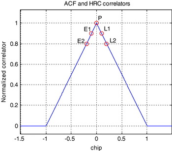
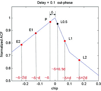
HRC is a software implementation of the gated correlator scheme. It constructs a discriminator with additional correlators arranged with properly designed chip space to approximate a gated correlator. The arrangement of the HRC correlator is shown in Figure 1 and its mathematical definition is described in Equation (1). The main difference between HRC and a conventional early-minus-late discriminator is that the former uses two couples of early and late correlators, namely early1-minus-late1 and early2-minus-late2. These correlators construct the HRC discriminator, D HRC, as shown in Equation (1).
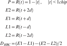
where:
- d
chip space (chip),
- R(·)
autocorrelation function,
- P,E1,E2,L1,L2
autocorrelation outputs for specified delays respectively,
- D HRC
HRC discriminator.
Auto-correlation function (ACF) and construction of HRC.

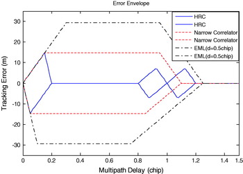
The multipath mitigation performance of a conventional early-minus-late narrow correlator and HRC is shown in Figure 2. A general early-minus-late (EML) discriminator uses 0·5 chip-spaced early and late correlators, the narrow correlator uses 0·2 chip-spaced ones and HRC is constructed with two 0·2 and 0·4 chip-spaced early and late correlator pairs by setting d in Equation (1) to 0·1. A general EML causes a maximum tracking error of about 30 m and a narrow correlator bounds the error to 15 m. Even though the narrow correlator reduces the error, it cannot remove it. HRC shows similar mitigation performance to the narrow correlator for short-delayed multipath, but for mid-delayed multipath, it removes perfectly the multipath-induced error. This is the merit of the HRC scheme.
Multipath error envelopes of EML, narrow correlator and HRC.

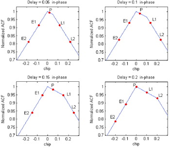
Although HRC can eliminate the mid-delayed multipath-induced error, a short-delayed multipath-induced error still remains, just like the narrow correlator scheme. This is the unsolved problem of HRC. In this paper, we propose a modification of HRC in order to remove or reduce the short-delayed multipath-induced error. The modification stems from geometric analysis of the ACF and correlator arrangements when HRC operates against a short-delayed multipath and induces a remaining tracking error. Assuming that the correlator space d is set to 0·1 chip, the geometries of ACF and the HRC tracking error were analysed for several multipath delays. Simulation was performed for the LOS signal plus one in-phase multipath with half the amplitude of the LOS signal by setting α=0 in Equation (2), two-path signal model. The simulation was based on assuming perfect carrier wipe-off and thus code-only simulation. Figure 3 shows the simulation results for 0·05, 0·1, 0·15 and 0·2 chip multipath delays, respectively.

where:
- s(t)
two-path signal model,
- A
signal amplitude,
- α
relative multipath signal amplitude,
- μ
multipath delay
- ω0
carrier frequency,
- φ0
nominal carrier phase,
- C(·)
pseudo noise (PN) code (GPS C/A code),
Geometry of ACF and HRC tracking status for in-phase multipath.

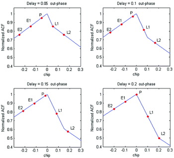
The necessary condition for HRC to be able to remove the multipath-induced error is that both E1 and E2 should be located on the same line adjacent to the left side of the correlation peak and also that L1 and L2 should be located on the same line adjacent to the right side of the peak. From Figure 3, for HRC implementation with d=0·1, the multipath signal delayed below 0·2 chip cannot satisfy the necessary condition. Thus, for 0·05, 0·1 and 0·15 chip-delayed multipath signals, the HRC could not find the true correlation peak and it located a prompt correlator on the right side of the true peak. When a multipath signal delay of more than 0·2 chip is induced, HRC can eliminate its error properly and the prompt correlator comes to be located on the true peak, as shown in Figure 3. For out-of-phase multipath signals, distorted geometry of ACF and HRC operation is shown in Figure 4.
Geometry of ACF- and HRC-tracking status for out-of-phase multipath.

An out-of-phase multipath distortion of ACF is different from an in-phase multipath, and causes different aspects of HRC-tracking performance. As seen in Figure 4, multipath delay below 0·2 chip causes an unsettled tracking error in HRC similar to in-phase multipath, but the prompt correlator containing the error is located on the left of the correlation peak. Moreover, the correlator position appeared in two ways, with delays below 0·05 chip and between 0·05 and 0·2 chip. Between 0·05 and 0·2 chip delay, L1 and L2 are not on the same line, with only L1 being located on the line on the right, adjacent to correlation peak. Below 0·05 chip-delay, both L1 and L2 are on the same line but it is not the adjacent line to the correlation peak. These aspects of ACF geometry and HRC operation are the starting point of HRC modification.
3. MODIFIED HRC CONCEPT
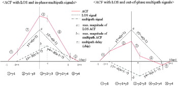
It is widely known that the occurrence of long-delayed multipath, about 300 m in the GPS C/A code, is rare or nearly impossible (McGraw and Braasch, Reference McGraw and Braasch1999, p336). Therefore, the short- and mid-delayed multipath signals are the main concern of the multipath mitigation technique. The purpose of a modified HRC is to improve the mitigation performance for short-delayed multipath. Our new method is based on geometrical analysis of distorted ACF by multipath signal. As shown in the previous figures, the tendencies of in-phase and out-of-phase multipath-induced ACF distortions are different from each other, and the new method will be addressed for each case separately as shown in Figure 5.
ACF with LOS and in-phase multipath signals (left) and ACF with LOS and out-of-phase multipath ones (right).

3.1. In-phase multipath
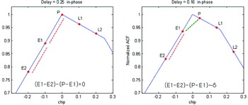
The situation that HRC could not remove the multipath-induced error for in-phase multipath was shown in Figure 3. The HRC constructed with d=0·1 could not remove a multipath delayed below 0·2 chip. For the in-phase multipath, we concentrated on multipath in the range 0·15–0·2 chip-delay where P and L1 are on the same line. Figure 6 shows the different circumstances when HRC works well or not. Figure 6 (right) shows the ACF and HRC operation when the 0·16 chip-delayed multipath was induced.
Geometry of ACF and HRC operation for in-phase multipath when the HRC works well for mid-delayed multipath (left) and it could not work for short-delayed one (right).

As stated in the previous section, the short-delayed multipath caused HRC to fail tracking the true correlation peak. For the 0·16 chip-delayed in-phase multipath, the mis-tracked prompt correlator was located on the right of the true peak, as shown in Figure 6 (right). From a geometrical standpoint, the in-phase multipath caused the slope of the right line adjacent to the true peak to decrease and it resulted in wrong peak tracking. The difference in slope between the lines on which L1 and L2 were located caused the prompt to move from the true peak to the right. However, in this case, in contrast to L1 and L2, E1 and E2 were always on the same line adjacent to the true peak on the left. Therefore, the slope between E1 and E2 could be a parameter indicating whether the prompt correlator is on the true peak or not. If the prompt were not on the true peak, it would always be to the right of the peak because of ACF distortion caused by the in-phase multipath. When HRC worked and removed the multipath-induced error, the slopes E1–E2 and P–E1 were expected to be the same, because E2, E1 and P must be on the same line, but when the short-delay multipath was induced and HRC could not work, the slope E1–E2 was larger than the slope P–E1 because P moved to the right side of the peak, and we found that the difference between the slopes E1–E2 and P–E1 was proportional to the HRC tracking error, δ. This is the key idea of the modified HRC concept.
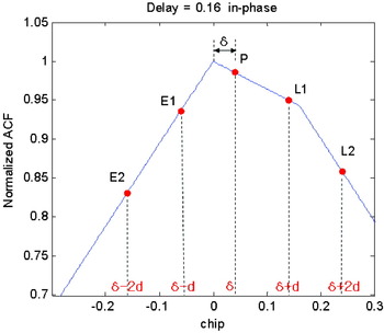
The geometrical analysis could be modelled as the mathematical description shown in Figure 7 and Equation (3). From Figure 7, set δ to be the HRC tracking error, d to be the chip space between HRC correlators, a to the ACF slope of LOS-only signal and b to the ACF slope of the multipath-only signal as used in Figure 5 (left). These parameters were used to model each correlator output as shown in Equation (3).
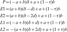
where:
- τ
multipath delay (chip),
- δ
HRC tracking error (chip),
- d
chip space (chip),
- a
absolute value of the ACF slope of LOS signal,
- b
absolute value of the ACF slope of multipath signal,
Parameters of HRC correlators when in-phase multipath is induced.

The slope difference between E1–E2 and P–E1 from Equation (3) could be derived as in Equation (4). The result of the slope difference was δ, the HRC-tracking error induced by the multipath, scaled by 2a. This means that Equation (4) could be used as an indicator to detect the HRC-tracking error.

The exact tracking error was derived as Equation (5). From the correlation values, E1, E2, P and L1, the HRC-tracking error could be calculated.
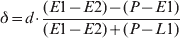
The numerator of Equation (5) is the slope difference that indicates whether HRC worked well or not, and the denominator and parameter d were used to eliminate the scale, 2a. When HRC works well, the numerator goes to 0, but if it could not work well, Equation (5) results in the tracking error produced by HRC. Thus, by adding Equation (5) to the conventional HRC discriminator, not only the mid-delayed but also the short-delayed multipath-induced error could be eliminated. Equation (6) shows how the discriminator of modified HRC works. This is the modified HRC concept for in-phase multipath.

where:
- Discr
discriminator function of modified HRC,
- D HRC
discriminator function of conventional HRC,
- D mod HRC
augmentation value (estimated HRC tracking error).
3.2. Out-of-phase multipath
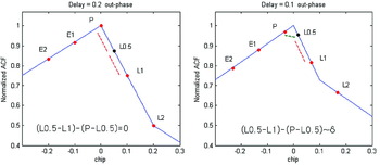
The geometry of ACF after inducing an out-of-phase multipath with half the LOS amplitude is shown in Figure 8. Figure 8 (left) shows the case when HRC worked well, and Figure 8 (right) is the case when HRC could not cope with the out-of-phase multipath-induced error, the delay between 0·05 and 0·2 chip.
Geometry of ACF and HRC operation for out-of-phase multipath when the HRC works well for mid-delayed multipath (left) and it could not work for short-delayed one (right).

Out-of-phase multipath makes the slope of the line adjacent to the right side of peak point steeper than the left line. Thus, a less inclined line is on the left side of the peak and it causes the prompt correlator to move to the left of the true peak point. Equation (4) could not be used in this case. Instead of E1 and E2 that are always on the same line and therefore are used as an indicator for in-phase multipath, L1 and L2 could be candidates to be used as indicator for the out-of-phase multipath. But when the 0·05 to 0·2 chip-delayed multipath was induced, L1 and L2 were not on the same line. And for below 0·05 chip-delayed multipath, L1 and L2 were on the same line, but it is not the line adjacent to the correlation peak. Just like the case of in-phase multipath, the indicator detecting a tracking error needs at least two correlation values on the same line adjacent to the peak point. Therefore, an additional correlator would be required to satisfy this condition. So, a 0·05 chip-space from the prompt correlator was added, called L0·5, as shown in Figure 8. Now, when the 0·05–0·2 chip-delayed multipath was induced, L0·5 and L1 would be always on the same line. So, the slopes L0·5-L1 and P-L0·5 could be used as an HRC-tracking error indicator for the out-of-phase multipath, just like the E1-E2 and P-E1 were used for the in-phase multipath. Figure 9 shows the geometry of ACF with the HRC operation status and their mathematical description is given in Equation (7) by applying equations in Figure 5 (right).
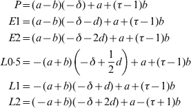
By using the derivations of Equation (7), the HRC-tracking error estimate, δ, is calculated as in Equation (8). The error was scaled by −2a:

The exact tracking error estimate could be calculated as shown in Equation (9), by using E1, P, L0·5 and L1.

A discriminator of the modified HRC for out-of-phase multipath was constructed as described in Equation (10).

where:
- Discr
discriminator function of modified HRC,
- D HRC
discriminator function of conventional HRC,
- D mod HRC
augmentation value (estimated HRC tracking error).
Parameters of HRC correlators when in-phase multipath is induced.

The modified HRC discriminator of Equations (6) and (10) can completely remove the multipath-induced error for in-phase multipath delays of 0·15 to 0·2 chip and for out-of-phase multipath delays 0·05 to 0·2 chip by augmenting the error with the estimated one. Exact estimation of the HRC-tracking error is possible only for these regions of multipath delays. However, in addition to complete elimination of the 0·15 to 0·2 chip-delay for in-phase and 0·05 to 0·2 chip-delay for out-of-phase multipath, our simulations show that the modified HRC could dramatically reduce the error for a shorter delay in each case, even though it could not remove the error completely. The performance of modified HRC for overall multipath delays will be shown in section 4.
3.3. In-phase and out-of-phase multipath determination
In sections 3.1 and 3.2, the modified HRC concept for in-phase and out-of-phase multipath was addressed with a geometrical approach and mathematical derivation, respectively. However, the receiver is unaware whether the incoming multipath signal is in-phase or out-of-phase, and thus a decision rule that could determine either of them is required.
Two decision parameters were developed and used in two stages. The first parameter was the reuse of the HRC-tracking error estimator shown in Equation (4). For d=0·1 HRC construction, if and only if an in-phase multipath with short delay (below 0·2 chip) is induced, this parameter always shows a non-zero value. For an out-of-phase multipath with short delay however, it always results in zero. Thus, for the first decision parameter, the slope difference between E1-E2 and P-E1 was used. Concentrating on the short-delayed multipath, it would be the best solution to discriminate between in-phase and out-of-phase multipath.
The second parameter uses the difference between the end correlation values of each side, E2 and L2. For in-phase multipath, the slope of the left-adjacent line of the true correlation peak is larger than the right-adjacent line. Thus, except for a very short delay, L2 is larger than E2, but when the out-of-phase multipath is induced, the situation is reversed. For an out-of-phase multipath, E2 is larger than L2. The second parameter could be used as a detector of mid-delayed multipath signals. Equation (11) shows the two decision parameters. The simulated outputs of each parameter are shown in Figure 10.
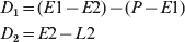
where:
- D 1
decision parameter 1,
- D 2
decision parameter 2.
In-phase and out-of-phase multipath decision parameter 1 and 2.

As expected, for short-delay multipath, decision parameter 1 shows a clear difference between the in-phase and out-of-phase multipath, but in the mid-delay region parameter 1 shows near-zero value for both in- and out-of-phase multipaths, because when the multipath delay is above 0·2 chip (mid-delayed) the HRC modification terms go to zero. However, for mid-delayed multipath above 0·2 chip, the parameter 2 shows clear difference. Finally, by using both the parameter 1 and 2, in-phase and out-of-phase multipath determination could be done.
4. SIMULATED PERFORMANCE OF MODIFIED HRC
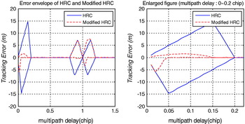
Until now we have dealt with the modified HRC concept. Now its performance will be shown by simulation of the multipath error envelope. The modified HRC for in-phase and out-of-phase was implemented with in- and out-of-phase decision parameters. The simulation was performed for GPS C/A code LOS signals and half amplitude of the LOS multipath signal, the two-path signal model. The chip space of each HRC correlator was set to 0·1 chip. Figure 11 shows the result.
Simulated error envelope of modified HRC (left) and an enlarged plot for short delay below 0·2 chip (right).

From Figure 11, the maximum HRC tracking error induced by multipath was about 15 m when a short-delayed multipath occurred. The modified HRC reduced the maximum HRC tracking error from 15 to 2 and 5 m for in-phase and out-of-phase respectively. From Figure 11 (right), the induced errors of the 0·15 to 0·2-chip delayed multipath for in-phase and the 0·05 to 0·2 chip-delayed for out-of-phase are completely removed, as seen in the mathematical derivation. And as stated, the induced error was dramatically reduced not only for these perfectly removable delay regions but also for other short-delayed multipath signals. For the in-phase multipath with 0 to 0·15-chip delay, the maximum error reduced from 15 to about 2 m, and for the out-of-phase multipath with 0 to 0·05 chip delay, the maximum error reduceds from 15 to about 5 m. Considering that short-delay multipath occurs most frequently, this could be a big improvement. Moreover, the performance of multipath mitigation for medium and long multipath delays was similar to the conventional HRC.
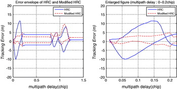
Figures 12 and 13 show the error envelopes when 24 MHz and 12 MHz pre-correlation bandwidth were applied. The filter was implemented by a 5th order Butterworth filter. Because of group delay and undesired ACF distortion by the filtering process, tracking error occurred in the mid-delayed region. From the figures, the modified HRC showed improved performance, even though the performance was degraded compared with a simulated infinite pre-correlation bandwidth.
Simulated error envelope of modified HRC with 24 MHz bandwidth (left) and an enlarged plot for short delay below 0·2 chip (right).

Simulated error envelope of modified HRC with 12 MHz bandwidth (left) and an enlarged plot for short delay below 0·2 chip (right).

The simulation results shown in Figures 11, 12 and 13 verified that the proposed modified HRC method worked well and improved the performance of HRC for short-delayed multipath. Performance degradation of modified HRC with decreasing bandwidth was observed not only for the proposed method, but also for most multipath mitigation methods, including conventional HRC.
5. IMPLEMENTATION ISSUES
5.1. Noise problem
So far, we have dealt with the modified HRC concept and the expected performance without considering noise. It is well known that noise sensitivity is a deficiency of HRC (McGraw and Braasch, Reference McGraw and Braasch1999), and because modified HRC is based on the conventional HRC, it has the same problem. Unlike the conventional early-minus-late discriminator and narrow correlator using only one pair of early and late correlation values, the HRC uses two pairs of early and late correlation values, i.e., not only E1-L1 but also E2-L2,as shown in Equation (1). An additional pair of early and late is a source of increased noise. By the way, the modified HRC adds addition, subtraction and division of correlation values to the conventional HRC, and it was inferred that modified HRC would be noisier than the conventional one.
The proposed modified HRC provided better multipath mitigation performance than without the technique when multipath was induced, even though it could be noisier. However, for normal conditions where the multipath does not exist, the mitigation technique can cause increased noise in the tracking performance than without it. Therefore, the implementation of the modified scheme needs long pre-detection integration time and narrow bandwidth of tracking loop filter. And just as in other mitigation techniques, when wide pre-correlation bandwidth is used and sharp ACF can be obtained, its performance improves.
5.2. In-phase and out-of-phase multipath detection
As stated in section 3, two kinds of in-phase and out-of-phase multipath decision parameters were used. The values of the parameters could be varied when the method is implemented in a real GNSS receiver according to the signal to noise ratio (SNR) and the amplitude of the multipath signal. Thus, to set a threshold, the decision logic in using the parameters shown in Figure 10 needs some tuning.
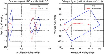
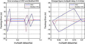
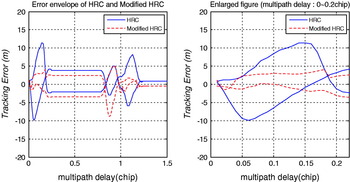
Considering that several hundred metres-delayed multipath rarely occurs, the decision process could be simplified using decision parameter 1 only. Figures 14, 15 and 16 show results obtained using parameter 1 only. Figure 14 (left) shows a tracking error higher than for conventional HRC at long-delayed multipath (about 1 chip-delay), but for short- and mid-delayed multipath, the modified HRC works well, just like using a two-stage decision rule. There is an excessive tracking error at about 0·8 chip delay and also a nearly perfect error reduction after 1 chip delay compared to conventional HRC. As mentioned before, however, long delayed multipath is not a matter of concern. Figures 15 and 16 show the error envelopes when the 24 MHz and 12 MHz pre-correlation bandwidth were applied. Some different aspects of multipath-induced error from the conventional HRC for mid-delay multipath occurred, but the overall magnitude of the error was similar to the conventional HRC.
Simulated error envelope of modified HRC using parameter 1 only (left) and an enlarged plot for short delay below 0·2 chip (right).

Simulated error envelope of modified HRC with 24 MHz bandwidth using parameter 1 only (left) and an enlarged plot for short delay below 0·2 chip (right).

Simulated error envelope of modified HRC with 12 MHz bandwidth using parameter 1 only (left) and an enlarged plot for short delay below 0·2 chip (right).

6. EXPERIMENTAL TEST RESULTS
The modified HRC was implemented on our own made software receiver and tested using a simulated GPS signal with one in-phase multipath. The simulated GPS signal was generated without a carrier, by assuming that the carrier was perfectly demodulated, the receiver performed coherent tracking, and that the amplitude of the multipath signal was half of the LOS signal, without considering noise and pre-correlation bandwidth. In the software receiver, the modified HRC was implemented with 0·1 chip spaced between all correlators except L0·5 which was 0·05 chip spaced from the prompt correlator. The loop bandwidth of DLL was set to 25 Hz and the pre-detection integration time was 1 ms.
The test was performed in two ways. First, the multipath mitigation performance of several schemes including modified HRC was verified for several multipaths having fixed delay each. Second, a multipath signal with linearly increasing delays was tested. The multipath delay was changed from 0 to 0·3 chip for 60 s. It was expected that the performance of the second test would be similar to the simulated error envelope. A narrow correlator, a conventional HRC and a modified HRC were used for the test. For the narrow correlator, the early and late chip space was set to 0·2 chip to create the same condition as HRCs. The chip space of the HRCs was set to 0·2 chip for E1-L1 and 0·4 chip for E2-L2. This means that E2, E1, P, L1 and L2 were separated 0·1 chip from each other, d=0·1 of Equation (1).
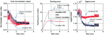
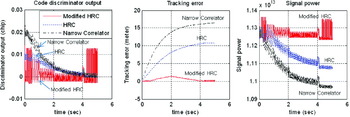
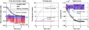
The results of the first test are shown in Figures 17–20 for 0·05, 0·1, 0·15 and 0·2 chip-delayed multipaths, respectively. The simulation results are displayed with three pictures. The left side picture shows the code discriminator output that does not have the tracking loop filter applied. The middle picture shows the tracking error, the difference between the tracked code delay and the true one, and the right side picture shows the magnitude of the prompt correlator accumulation value that means tracked signal power. The larger the magnitude of the prompt correlation is, the more accurate the tracking performance.
Fixed 0·05 chip delayed in-phase multipath, code discriminator output (left), tracking error (middle) and tracked signal power (right).

Fixed 0·1 chip delayed in-phase multipath, code discriminator output (left), tracking error (middle) and tracked signal power (right).

Fixed 0·15 chip delayed in-phase multipath, code discriminator output (left), tracking error (middle) and tracked signal power (right).

Fixed 0·2 chip delayed in-phase multipath, code discriminator output (left), tracking error (middle) and tracked signal power (right).

In Figure 17 (left), the modified HRC shows a very noisy discriminator output, but its multipath-induced tracking error is much smaller and tracked signal power is larger than from the narrow correlator and conventional HRC as observed from the plots of the tracking error in Figure 17 (middle) and signal power in Figure 17 (right). For 0·1 chip-delayed multipath, Figure 18 (middle) shows a tracking error of 5 m for modified HRC compared to more than 10 m of other schemes, and a clear difference in tracked signal power is also shown in Figure 18 (right), as expected from the simulated error envelope. In these figures, the modified HRC could not remove the multipath-induced error, but could reduce its magnitude.
Figures 19 and 20 show the tracking performance for multipath delayed more than 0·15 chip. In Figure 19 (middle) the narrow correlator gave rise to a tracking error of about 15 m and HRC caused about 10 m, but modified HRC reduced the error to zero after 4 s. Except for modified HRC, other schemes have an un-removed tracking error. A delayed multipath larger than 0·2 chip could be treated by conventional HRC, as shown in Figure 20. In Figure 20 (middle), conventional and modified HRC could remove the error, except for the narrow correlator scheme. A noisier characteristic of the modified HRC discriminator output than HRC and the narrow correlator can be identified in Figure 20 (left). As stated earlier, by increasing the pre-detection integration time and narrowing the tracking loop bandwidth, the noise problem can be complemented.
For the second test, the tracking result of a linearly increasing delayed multipath signal is shown in Figure 21. The multipath delay was continuously increased from 0 to 0·3 chip for 60 s. Therefore, the tracking error of Figure 21 is equivalent to the simulated error envelope, 0 s is equivalent to 0 chip-delay and 60 s is equal to 0·3 chip. As expected in the simulation, the tracking error of the narrow correlator increased for 30 s (equivalent to 0·15 chip delay) and then maintained the error. The HRC worked well and removed the multipath-induced error after 40 s (equivalent to 0·2 chip-delay), but before 40 s, it caused a tracking error of 15 m at its maximum. Compared to these techniques, modified HRC removed the multipath-induced error from 30 s (equivalent to 0·15 chip-delay) onwards, and reduced the maximum tracking error to 5 m, which is one third of conventional HRC.
Linearly varying delayed multipath from 0 to 0·3 chip during 60 seconds, code discriminator output (left), tracking error (middle) and tracked signal power (right).

7. CONCLUSIONS
HRC is one of the most powerful multipath mitigation techniques in the non-parametric approach. The outstanding performance is its mitigation for mid-delayed multipath-induced error. However, for short-delayed multipath the performance of HRC is not satisfactory. In the situation that below mid-delayed (including short-delayed multipath) occurs in real world, the lack of a countermeasure against short-delayed multipath could be a severe problem. Therefore, this paper proposed a solution for short-delayed multipath, the modified HRC technique.
Some mathematics and analysis of distorted ACF geometry showed that the tracking error of HRC could be estimated when short-delayed multipath was induced. The simulated tracking error envelope was then constructed. It showed that the modified HRC removed multipath-induced errors for the shorter-delayed multipath, namely 0·15 chip for in-phase and 0·05 chip for out-of-phase compared to 0·2 chip for the conventional method with d=0·1 chip HRC construction. In addition to the removal, the method reduced the maximum tracking error from 15 to 5 m.
For verification, we implemented the modified HRC to a software receiver and performed experimental tracking tests with simulated multipath-induced signals. As expected from the simulation, the method worked well and showed outstanding multipath mitigation performance for short-delayed multipath. Even though it causes noisier characteristics than conventional HRC, some complementary schemes, such as long integration time and narrow loop filter bandwidth, could help the problem. Moreover, by using some techniques for roughly detecting the amount of multipath delay, modified HRC for short delay and other techniques for mid-delay or the normal condition in which multipath does not exist could be used together. Despite its outstanding performance for short-delayed multipath and compatible performance to conventional HRC for the mid-delayed multipath, the modified HRC is simpler and easier to implement than any other scheme and it could be a useful approach to cope with short and mid-delayed multipath.
ACKNOWLEDGEMENT
The study was supported in part by the Brain Korea 21 (BK-21) Program for Mechanical and Aerospace Engineering Research, the Institute of Advanced Machinery and Design, and Institute of Advanced Aerospace Technology at Seoul National University.