Introduction
Nowadays, due to increase in the demand of wireless components such as antennas, which are compact devices with low profile are very much essential with good performance. Compact antennas required to work at multiple frequencies with good isolation and provide ease of tuning between frequency bands. Many designs are available to obtain dual band [Reference Zhang, Da Liu, Wu, Ye, Li and Wu1, Reference Ambekar and Deshmukh2], triband, and multiple bands. In paper [Reference Ta, Phung, Nguyen and Nguyen-Trong3], a dual-band antenna with tri-polarization is obtained using slotted patch technique. Triple-band antennas are essential in few applications which work simultaneously at three resonant frequencies are proposed in papers [Reference Viswambharan Anil Kumar, Paul and Mohanan4]–[Reference Li, Yang, Xue and Che6]. A few designs on multiband antennas are proposed in papers [Reference Sharma, Awasthi and Singh7]–[Reference Ezzahry, Elhamadi, Lamsalli and Touhami10] which are essential in wireless applications. Recently, many multiband designs are proposed for Ultra Wideband (UWB) applications [Reference Wu11], mobile handsets [Reference Seddiki, Nedil, Tebache and Hadji12], and fast redesign method for wireless application [Reference Pietrenko-Dabrowska and Koziel13]. Also independently tuned frequency bands are proposed using diodes [Reference Asif, Anbiyaei, Ford, O’Farrell and Langley14, Reference Fabian-Gongora, Martynyuk, Rodriguez-Cuevas, Martinez-Lopez, Martinez-Lopez and Martinez-Lopez15]. Above designs possess linear polarization (LP) which requires perfect line of sight for better signal reception, but circular polarization (CP) has advantageous than LP in terms of orientation, interference, fading, and immune to noise. So CP antennas are much essential in wireless applications. A few CP designs are proposed to cover dual band [Reference Hyun, Sung and Kim16], triband [Reference Tan and Chen17], and multiband [Reference Yang, Qi, Chen and Li18, Reference Abdalrazik, Gomaa and Afifi19] used in different applications. All these designs are not capable of tuning frequency bands, but a few antennas are designed to achieve frequency reconfigurability [Reference Nguyen-Trong, Piotrowski and Fumeaux20]–[Reference Bharadwaj, Sipal, Yadav and Kishen Koul22] and independent tuning of frequency bands [Reference Lin, Yu, Mei, Jiang and Yu23, Reference Bai, Singh, Ford, O’Farrell and Langley24]. PIN diodes and varactor diodes are used to obtain reconfigurability and independent tuning capability, but the design requires complex fabrication and external circuit. A few metamaterial-based designs are proposed to achieve dual- and triple-band operation with independent tuning, which provides ease of fabrication. These designs produces LP [Reference Paul, Kandasamy and Sharawi25] and CP [Reference Kandasamy, Majumder, Mukherjee and Ray26]–[Reference Tharehalli Rajanna, Rudramuni and Kandasamy28], but they uses multiple stripsand SRRs to achieve desired result. In the proposed design, a compact antenna with single strip SRR and two cross strips provide the intended result with good axial ratio bandwidth (ARBW).
In this paper, a single SRR and cross strips loaded circular polarized modified slot antenna is designed and validated through experiment. The slot antenna is modified in its corner to provide CP in first band. The corner expansion method provides two degenerative modes required to produce CP. Second band is generated due to loading of single SRR. A dual split produce orthogonal electric field to obtain CP. The third band is obtained through the asymmetric length cross strips. By varying the length of strips, orthogonal phase is achieved to obtain CP. All bands are tuned independent to each other. The sense of polarization is LHCP (left-hand circular polarization) for first two bands and RHCP (right-hand circular polarization) for third band. These polarization sense also can be tuned by changing the orientation of individual element.
Design principle
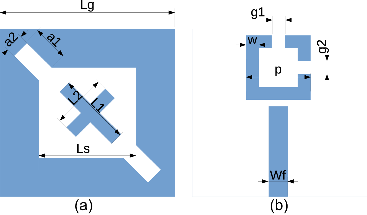
The proposed triband antenna is shown in Fig. 1. The front and back views are shown in Fig. 1(a) and (b). The modified slot is etched in the front side of the ground plane and cross strips are placed. The microstrip line is used for excitation and it is etched on the backside. The SRR is placed at a distance of 2 mm from the feed line. The substrate material used for the design is Rogers 4003C ( $\epsilon_r = 3.38$, tanδ = 0.009). The dimensions of the antenna are provided in Fig. 1.
Antenna geometry. (a) Front view and (b) Back view. Lg = 50 mm, a 1 = 8 mm, a 2 = 4 mm, L 1 = 20 mm, L 2 = 18 mm, Ls = 36 mm, Wf = 3.1 mm, Lf = 25 mm, p = 18 mm, w = 2 mm, g 1 = 1.2 mm, g 2 = 1.4 mm.

Triple-band operation
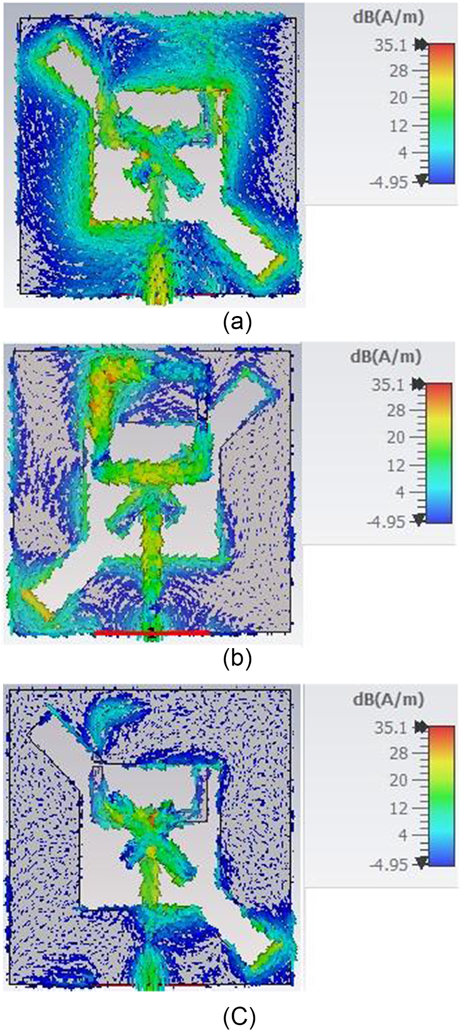
The mechanism for obtaining the triband operation is described in Fig. 2. Figure 2(a) shows the resonance obtained due to the square slot. The resonance frequency of slot antenna is obtained using Equation (1). The second band is achieved due to the asymmetric micro-split SRR and its surface current is shown in Fig. 2(b). Finally the third band is obtained using the cross strips and its surface current is shown in Fig. 2(c). The electric field of microstrip line excites the slot and cross strips. The slot and two strips are maximally coupled and produce the corresponding resonant frequency. The positioning of strips are 45∘ with respect to x-axis. The axial magnetic field excites the SRR. The proper orientation and position gives maximum coupling, which is modeled as LC resonant circuit and provide resonance
 \begin{equation}
fr=\frac{c}{2L_s}\sqrt{\frac{2}{1+\epsilon_{eff}}}
\end{equation}
Surface current distribution on (a) modified slot, (b) cross strips, and (c) SRR.

where ϵeff is the effective dielectric constant.
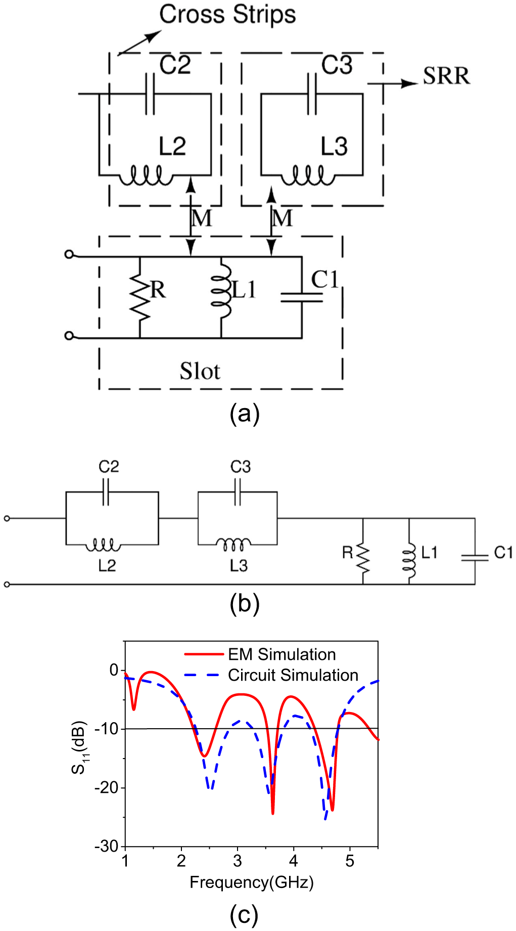
The equivalent circuit of the proposed design is shown in Fig. 3(a). It consists of slot resonance which has shunt LC circuit. The energy coupling from slot excites the strips and SRR which is shown by mutual coupling in the circuit. The strips comprises of LC circuit which provides resonance due to current flow in the strips. The current flow gives inductance and the capacitance is in parallel with inductance due to separation of dielectric from strips and ground plane. The SRR has magnetically coupled from slot which has current flow in the loop of SRR. The current flow in SRR loop provides inductance and the capacitance is obtained due to multiple splits in the SRR. The values of inductance and capacitance are calculated using well-known resonance equation and provided in Fig. 3. The simulation of equivalent circuit is carried out using ADS simulator and the performance of S 11 is compared with Electromagnetic (EM) simulation. The S 11 performance of circuit and EM simulation is well in agreement and it is shown in Fig. 3(b). The values of optimized lumped elements are given by R = 4.41 kΩ, L 1 = 0.31 nH, C 1 = 6.06 pF, L 2 = 0.26 nH, C 2 = 3.89 pF, L 3 = 0.94 nH, C 3 = 4.9 pF.
(a) Equivalent circuit of energy coupling form slot to strips and SRR, (b) equivalent circuit of proposed design, and (c) S 11 comparison between EM and circuit simulation.

CP mechanism
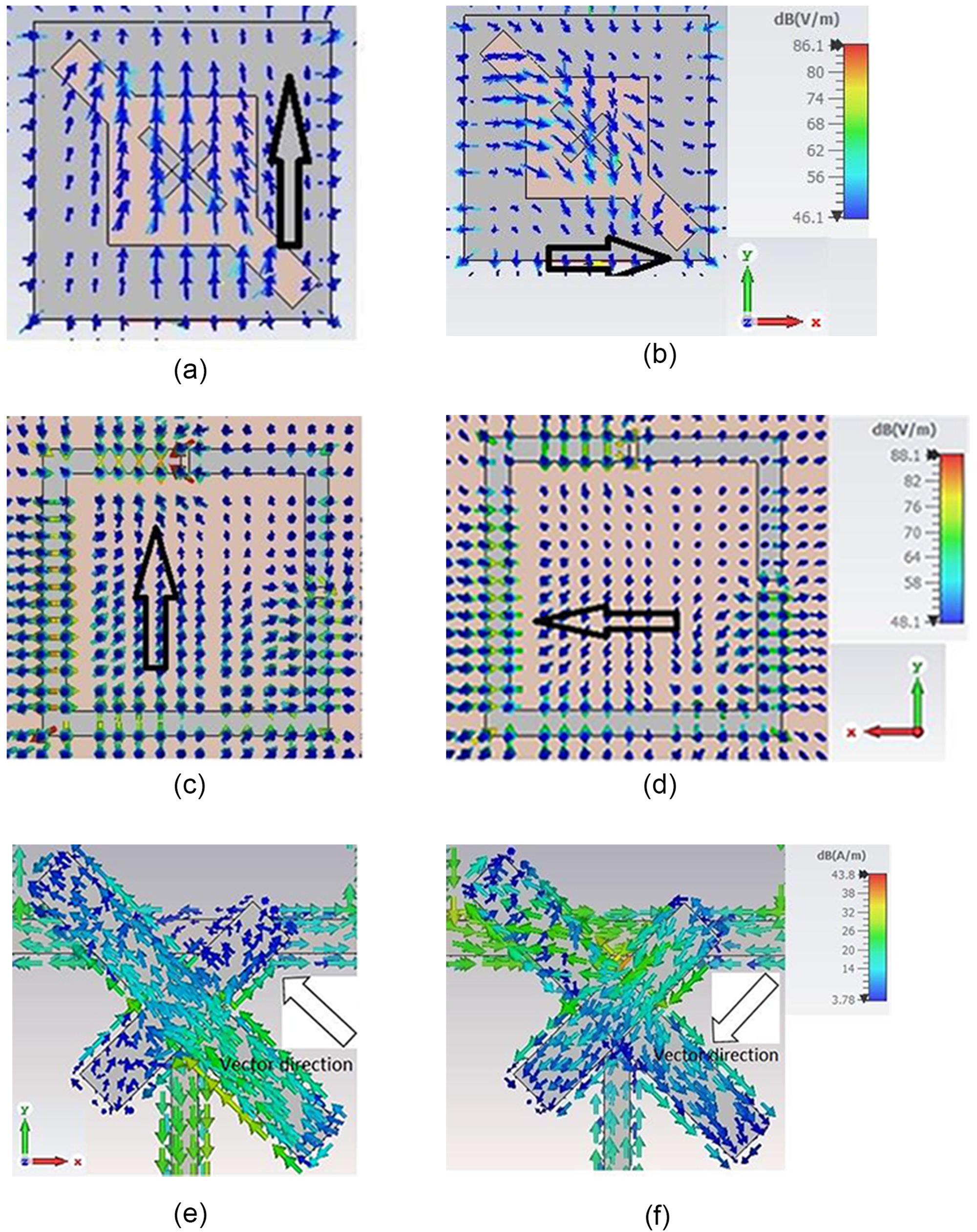
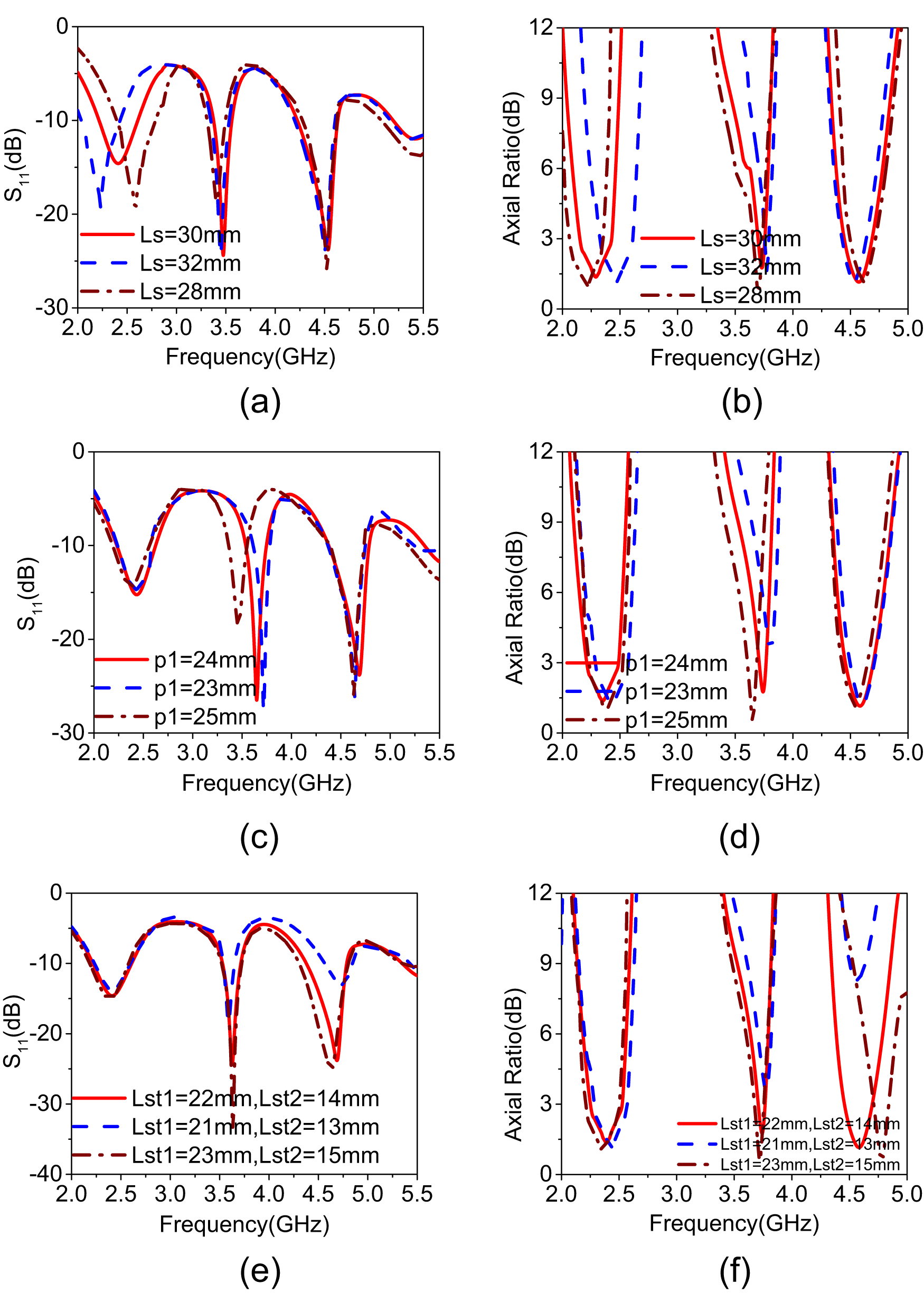
The mechanism of obtaining CP in each band is described here. The first band is obtained due to square slot antenna. The square slot is extended in its corner to obtain two degenerative modes. The extended slots are optimized to get the orthogonal modes which are required for CP. The second band is achieved using a single SRR with dual micro-splits. The splits are in asymmetric gaps which produces the orthogonal electric fields, that intern generates CP. The third band is obtained by loading the cross strips on the slot. By varying the length and width of the strips, CP is obtained. Here the sense of polarization of third band is RHCP, while first and second band is LHCP. Here the electric field or surface current distribution is shown with respect to +z direction, so that the dual-sense polarization is seen. To validate the antenna resonates CP due to each of the individual structure, the electric field and surface current distribution is shown in Fig. 4. In the figure, Fig. 4(a) and (b), the electric field distribution of modified slot is seen, the field vectors rotate in the clockwise direction toward +z-axis producing the LHCP. Figure 4(c) and (d) depicts the electric field distribution of SRR in −z direction and field vector rotates in anticlockwise direction producing LHCP. Figure 4(e) and (f) shows the surface current on the cross strips, which rotates vector anticlockwise in +z direction producing RHCP radiation. The sensitive parameters and independent tuning capability are found using the parametric variation. Figure 5(a) shows reflection coefficient of the slot variation, while keeping other structures constant. It shows that when the length of square slot is varied, there is a change in the resonance and axial ratio values. If the slot dimension increases, the resonance shifts toward lower frequency and if slot dimension decreases the resonance shifts toward higher frequency. The axial ratio plot is shown in Fig. 5(b). Similarly, the second resonance can be tuned using SRR dimension. The length of the SRR is varied and its corresponding changes in S 11 and axial ratio can be seen in Fig. 5(c) and (d). In the third resonance, tuning is obtained due to variation in the length of each strips. The tuning of S 11 and axial ratio plots of cross strips are observed in Fig. 5(e) and (f). From this parametric tuning, it is concluded that the dimension can be varied individually to tune the frequency bands independently without affecting the other frequency bands.
Electric field distribution of slot at (a)  $\omega \text{t}$ = 0∘ and (b)
 $\omega \text{t}$ = 90∘, electric field distribution of SRR at (c)
 $\omega \text{t}$ = 0∘ and (d)
 $\omega \text{t}$ = 90∘, and surface current distribution of cross strips at (e)
 $\omega \text{t}$=0∘ and (f)
 $\omega \text{t}$=90∘.

Parametric variation of slot antenna, SRR, and cross strips: (a) S 11 (Ls variation), (b) axial ratio (Ls variation), (c) S 11 due to p 1, (d) AR due to p 1, (e) S 11 (variation of  $L_{st1}$ and
 $L_{st2}$), and (f) AR (variation of
 $L_{st1}$ and
 $L_{st2}$).

Results and discussion
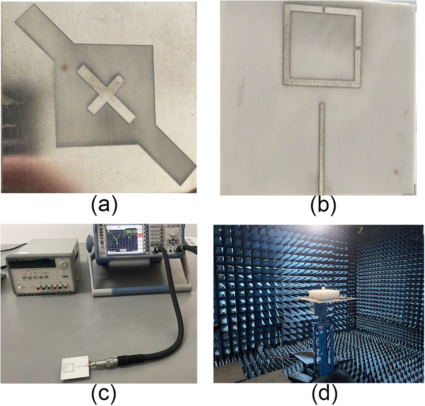
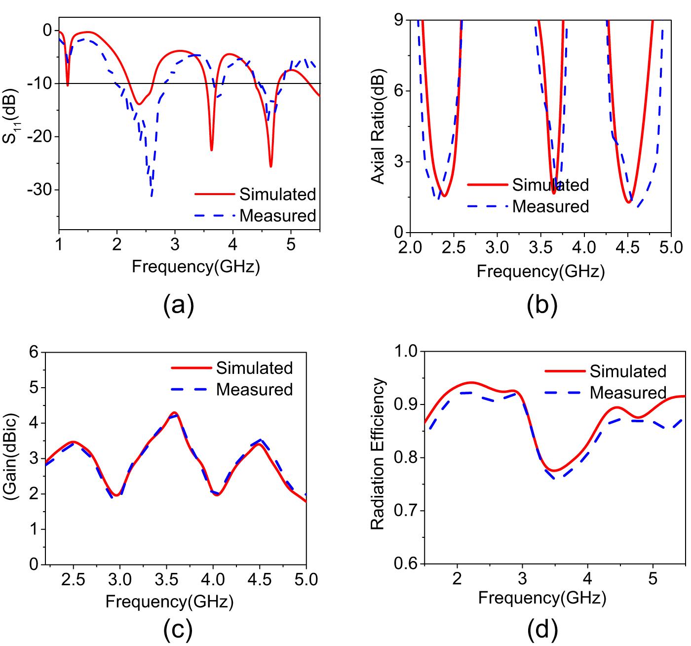
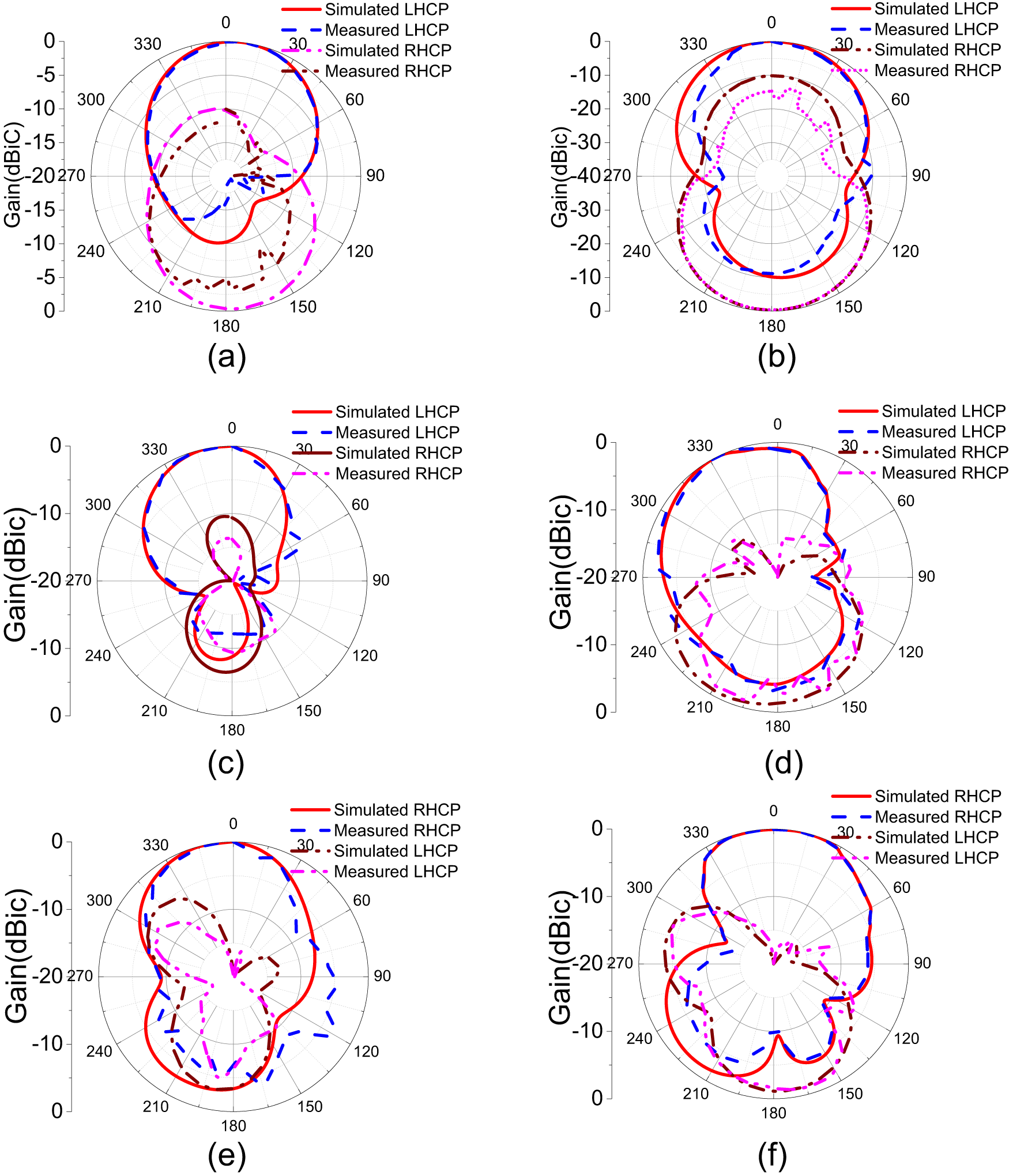
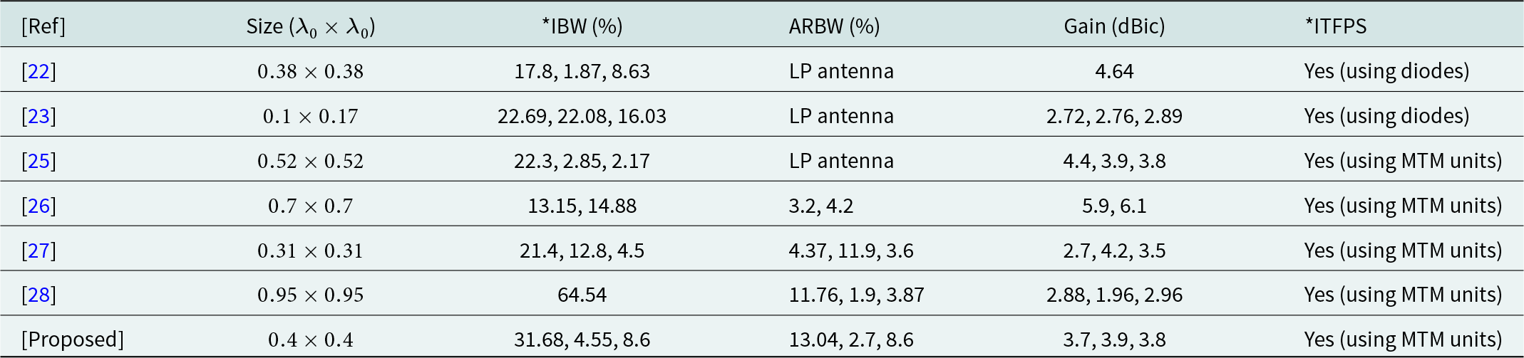
The proposed structure is fabricated and shown in Fig. 6. The design is experimentally validated using Vector Network Analyzer (VNA) and anechoic chamber. Figure 6(a) shows the front view, Fig. 6(b) shows the back view, Fig. 6(c) depicts the experimental setup to measure S 11, and Fig. 6(d) shows the picture of measuring various parameters in the anechoic chamber. The 50Ω Sub Miniature Version A (SMA) is used as connector for feeding the input power. The impedance bandwidth obtained in the simulation for all three frequency bands are 15.76%, 4.68%, and 8.07%. The measured impedance bandwidth are 31.68%, 4.55%, and 8.6%. Figure 7(a) shows the comparison between simulated and measured data of S 11. The simulated ARBW of 12.5%, 2.73%, and 6.66% is obtained in each band. The measured ARBW of 13.04%, 2.7%, and 8.6% is well correlated with simulated values at each frequency band and it is shown in Fig. 7(b). The simulated and measured peak gain value of 3.8 dBic, 3.9 dBic, and 3.7 dBic is obtained at corresponding resonance frequencies, which are well in agreement and it is depicted in Fig. 7(c). The simulated radiation efficiency is shown in Fig. 7(d) and it is more than 80% in all frequency bands. The radiation pattern of the proposed design is shown in Fig. 8. The antenna is well radiating CP waves in the broadside direction showing clear evidence of dual polarization. LHCP is produced in the first and second band, while RHCP is produced in the third band. The cross-polarization level of minimum −10 dB is obtained with respect to co-polarization at all frequency bands. Figure 8(a) and (b) shows the radiation pattern at 2.42 GHz, Fig. 8(c) and (d) shows the radiation pattern at 3.67 GHz, and Fig. 8(e) and (f) shows the radiation pattern at 4.6 GHz. The supremacy of proposed design is compared with previous literature is provided in Table 1. It can be noted that the compactness, miniaturization, bandwidth, axial ratio, gain, and tunability of the design is comparable and superior than some of the references. The ARBW is good compared with [Reference Paul, Kandasamy and Sharawi27] and [Reference Tharehalli Rajanna, Rudramuni and Kandasamy28]. The compact size is obtained when compared to all references cited in table except [Reference Paul, Kandasamy and Sharawi27]. The gain is more in all bands compared to few references such as [Reference Lin, Yu, Mei, Jiang and Yu23, Reference Paul, Kandasamy and Sharawi27] and [Reference Tharehalli Rajanna, Rudramuni and Kandasamy28].
Fabricated antenna: (a) front view, (b) back view, (c) measuring S 11 using VNA, and (d) antenna measured using anechoic chamber.

Comparison of simulated and measured results of (a) reflection coefficient (S 11 dB), (b) axial ratio (dB), (c) gain (dB), and (d) simulated radiation efficiency.

Radiation pattern of proposed antenna at 2.46 GHz (a) XZ plane and (b) YZ plane, at 3.67 GHz (c) XZ plane and (d) YZ plane, and at 4.6 GHz (e) XZ plane and (f) YZ plane.

Supremacy of the proposed design with previous articles

*IBW = impedance bandwidth, ITFPS = independent tuning of frequency bands and polarization sense.
Conclusion
The proposed structure is designed, simulated fabricated, and experimentally measured. The compact antenna radiates CP in three frequency bands with dual-sense polarization. The square slot antenna and SRR provides LHCP and cross strips gives RHCP. The measured impedance bandwidth of 770 MHz, 170 MHz, and 370 MHz are obtained in each band respectively. The ARBW of 300 MHz, 100 MHz, and 400 MHz are obtained and these are well agreement with simulated one. The peak gain of 3.8 dBic, 3.9 dBic, and 3.7 dBic is obtained along with radiation efficiency of 80%. The design is compact and well suitable for mobile and wireless application like the Bluetooth, n78 and n79 sub-6 GHz 5G applications, wherever CP is essential.
Acknowledgements
We thank Rogers Corporation for providing substrate materials to carry out fabrication of the design.
Competing interests
The author(s) declare none.

Vinaya Kumar Sugganapalaya Rajanna received his B.E. degree in Electronics and Communication Engineering and M.Tech degree in VLSI and Embedded Systems Engineering from Visvesvaraya Technological University, Belgaum, Karnataka, India, in 2009 and 2011, respectively. He is currently working toward his Ph.D. in the dept. of Electrical and Electronics Engineering, Ghousia College of Engineering, Ramanagara, affiliated to VTU, Belgaum, Karnataka, India. His field of research includes microelectronics, RF-VLSI, RFICs, MMICs, RF circuits, microwave engineering, and microstrip antennas.

Venkatesh T received his B.E. degree in Computer Science and Engineering from SJCIT, Karnataka, India, in 1995 and M.Tech in Computer Networks from SJCE, Mysore, India, in 1997. He received his Ph.D. in parallel computing and networks from Mysore University in 2016. He is currently working as a Professor in the dept. of Computer Science and Engineering at Ghousia College of Engineering, Ramanagara, India. His research interests are parallel computing, computer networks, computer algorithms for antennas, and image processing algorithms.

Puneeth Kumar Tharehalli Rajanna received his B.E. degree in Telecommunication engineering and M.Tech degree in Digital Communication Engineering from Visvesvaraya Technological University, Belgaum, Karnataka, India, in 2009 and 2013, respectively. He received his Ph.D. from National Institute of Technology Karnataka, Surathkal, Mangalore, India, in 2020. He is currently working as an Assistant Professor in the dept. of Electronics and Telecommunication Engineering at Siddaganga Institute of Technology, Tumkur. His field of research includes metamaterial-based antennas, leaky wave antennas, MMICs, RF circuits, microwave engineering, and microstrip antennas.

Shambulinga Mudukavvanavar received his B.E. degree in Electronics and Communication Engineering and M.Tech degree in Digital Communication Engineering from Visvesvaraya Technological University, Belgaum, Karnataka, India, in 2011 and 2013, respectively. He is currently working toward his Ph.D. in Electronics and Communication at R V College of Engineering, Bangalore, affiliated to VTU, Belgaum and Karnataka, India. His field of research includes microstrip antennas, RF and microwave circuits, and image processing algorithms.