


1. Introduction
Precision agriculture integrates advanced technologies into traditional farming practices, often limited by physical labor and insufficient data access [Reference Botta, Cavallone, Baglieri, Colucci, Tagliavini and Quaglia4]. By combining mobile platforms, advanced sensing, and AI-driven data analysis, this approach enables precise crop management through real-time field observations. Consequently, targeted interventions for plants are carried out only when necessary and in specific quantities [Reference Bechar and Vigneault2]. Precision agriculture relies on intelligent machinery for both accurate plant maintenance and continuous data collection on plant health and development. However, although the economic, environmental, and agronomic benefits are clear, the widespread adoption of these technologies among farmers remains limited to date [Reference Spagnuolo, Todde, Caria, Furnitto, Schillaci and Failla14].
Most robotic solutions are beginning to be deployed in controlled cultivation environments to address labor shortages and meet the demands of a competitive global food market [Reference van Henten, Bac, Hemming and Edan19]. Specifically, greenhouse automation is making a significant contribution in reducing the environmental footprint of agriculture. In these settings, biotic and abiotic factors, such as light, temperature, and soil moisture, can be strictly monitored and regulated to maximize yield by mitigating the inherent variability of open-field environments [Reference Tangarife and Díaz16].
Agricultural robotics development must also align with the sustainable development goals (SDGs), set by the United Nations to promote environmental sustainability, improve current and future well-being, and foster global sustainable development [18]. By adhering to precision agriculture principles and ensuring alignment with the SDGs, agricultural productivity can be increased, environmental impacts reduced, and working conditions improved for those in the sector [Reference Botta, Cavallone, Baglieri, Colucci, Tagliavini and Quaglia5].
From prototypes to commercial products, agricultural robots can perform a wide range of functions: monitoring crops, interacting with them, and performing tasks such as fertilizing, weeding, harvesting, and sampling. Accordingly, these service robots can be classified based on their size and design, ranging from compact autonomous devices to large, complex systems. Smaller platforms are designed to perform simpler tasks, such as weeding or crop monitoring, as their agility allows them to move easily between rows; larger systems, on the other hand, are used for intensive operations where greater power is essential [Reference Hernández, Mondragón, González and Pedraza11]. Specialized solutions have been developed for specific challenges. For example, Arad et al. [Reference Arad, Balendonck, Barth, Ben‐Shahar, Edan, Hellström, Hamming, Kurtser, Ringdhal, Tielen and van Tuijl1] developed a scissor-lift platform specifically for harvesting sweet peppers, while Birrell et al. [Reference Birrell, Hughes, Cai and Iida3] and Lehnert et al. [Reference Lehnert, English, McCool, Tow and Perez12] proposed solutions for similar agricultural tasks. Consequently, structural flexibility is becoming a key paradigm, enabling a single robotic platform to adapt to diverse environments and perform multiple functions by reconfiguring its mechanical architecture or modular components to meet specific operational needs. Therefore, a critical factor in the effectiveness of these platforms is the selection of chassis configuration and locomotion type, which dictates the robot’s ability to operate in complex field conditions. Within this framework, wheeled rovers offer a compact structure and high transmission efficiency. More importantly, the availability of mature steering models enhances maneuverability, providing the necessary stability and traction while minimizing soil compaction on deformable terrains [Reference Ding, Qi, Meng, Chen, Zhang, Mei, Li and Ye7].
In this context, several robotic platforms are adopting alternative chassis configurations and locomotion systems to improve maneuverability and adaptability in agricultural environments. In particular, in controlled environments such as greenhouses, the use of gantry robots is becoming widespread. Their design allows them to operate directly above the crops, ensuring a large working space and reduced soil compaction. Recent gantry robotic platforms, such as Hefty [Reference Guri, Lee, Kroemer and Kantor10] and AgriCruiser [Reference Truong, Lee, Irie, Panda, Jony, Ahmad, Rahman and Jawed17], adopt modular and reconfigurable architectures to adapt the frame geometry to different row spacings. At the same time, latest advancements indicate that robotic platforms equipped with steering drive units (SWD) offer high mobility and operational versatility. Rovers such as Thorvald II [Reference Grimstad and From9], BoniRob [Reference Ruckelshausen, Biber, Dorna, Gremmes, Klose, Linz, Rahe, Resch, Thiel, Trautz and Weiss13], and Ladybird Farm Robot [Reference Sukkarieh15] exploit SWD units to achieve highly maneuverable locomotion, making them promising solutions for complex agricultural environments. These adaptable robotic platforms are suitable for various environments and tasks, benefiting greatly from the use of SWD, which combine driving and steering in each wheel through independent rotation about a vertical axis, thereby enabling highly flexible navigation. Although Thorvald II and BoniRob are able to achieve omnidirectional motion, continuous
 $360^\circ$
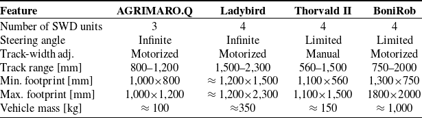
rotation is usually limited in practice by the cable routing to the traction motors on the wheels and on-board sensors. These platforms exemplify modularity and adaptability. BoniRob, in particular, features wheels mounted on adjustable arms, allowing the track width, wheelbase, and chassis height to be modified by repositioning the wheels relative to the frame. One variant of the Thorvald platform includes a pre-deployment adjustable chassis that enables track width variation. The Ladybird platform, on the other hand, mounts its two pairs of wheels on adjustable arms, allowing the track width to be adjusted according to the operational requirements. However, despite the benefits, using numerous SWD units can increase a platform’s weight and cost. In response to these challenges, researchers at Politecnico di Torino are developing a reconfigurable omnidirectional mobile robot for precision agriculture in greenhouses. This rover, called AGRIMARO.Q, introduces a reconfigurable gantry structure, which autonomously adjusts chassis track width and limits the need for multiple SWD units. This capability is particularly advantageous when the robot navigates between crop rows with varying widths. A concise comparison between AGRIMARO.Q and other state-of-the-art platforms is provided in Table I. This paper describes the functional design of the rover in Section 2, presents the platform kinematic model in Section 3, and it details the electrical and electronic system design in Section 4. Finally in Section 5, preliminary validation tests are presented to show the capability of the developed prototype.
Quantitative and qualitative comparison of omnidirectional agricultural gantry robots for greenhouses.

2. Functional design
The design of robotic systems for precision agriculture is closely tied to the specific operating environment. While the technological sophistication of the greenhouse and its infrastructure is one factor in assessing suitability, other critical considerations include the characteristics of the crops with which the robot will interact. Additionally, monoculture is relatively uncommon due to the diversity of agricultural landscapes; thus, fields often contain different crops with varying spacing requirements. Consequently, a robot capable of adapting to multiple crop types significantly broadens its application in both greenhouses and open-field environments. The AGRIMARO.Q robot is designed according to the following requirements:
-
• it should be lightweight to limit soil compaction, to improve safety, and to limit power consumption;
-
• it should have an omnidirectional mobility to improve versatility;
-
• it should be able to adjust its track to be used in different crops with varying spacing requirements.
For these reasons, the AGRIMARO.Q robot concept consists of a triangle-shaped gantry structure provided by three swerve-drive units positioned at each triangle vertexes, as shown in Figure 1. Moreover, a mechanism is adopted to modify the robot track according to the specific crop spacing requirements.
Concept of the AGRIMARO.Q robot.

Figure 1. Long description
The diagram illustrates the concept of the AGRIMARO.Q robot for precision agriculture. It features a top view of a field with green cubes representing plants. The robot is equipped with four swerve-drive units, each consisting of a wheel and a motor, allowing for precise movement and maneuverability. The diagram includes a detailed view of a swerve-drive unit, showing its components and how it functions. Additionally, there is a layout of the field with dimensions labeled as 1200 millimeters by 1000 millimeters, and a smaller section labeled as 800 millimeters by 1000 millimeters. The robot uses advanced sensing and AI-driven data analysis to monitor plant health and development, enabling targeted interventions for plants only when necessary and in specific quantities.
2.1. Track adjustment mechanism design
The robot track adjustment enhances the AGRIMARO.Q ability to navigate within different protected crop cultivation, also allowing a compact configuration when not used. As previously cited, the track modification is merely conceived as the linear translation of a single wheel steering axle across the rows transversal direction. This leads to the design of an exact or approximated straight-line mechanism with a limited number of links and joints, in order to reduce the complexity and weight of the AGRIMARO.Q system [Reference Eraslan8]. To systematically identify suitable architectures, planar mechanisms capable of generating exact or approximate rectilinear motion of a single output point were examined. The main selection criteria included: compactness along both axes, a reduced number of links and joints and the use of a single actuator. Figure 2 shows four possible solutions addressing the main design requirements. The drawing scale is the same in all diagrams. The trajectory of the steering axle attachment point
 $\mathrm{D}$
is marked by a solid blue line. To underline the assumed configuration for the mechanism actuation, which is done by means of a linear actuator connected between
 $\mathrm{A}_{0}$
and
 $\mathrm{B}$
in all cases, the sketches also report the trajectory of
 $\mathrm{B}$
point in a similar manner. The mechanism in Figure 2 (a) is a Scott–Russell linkage, where the orientation of the ternary element
 $\mathrm{CC}^\prime \mathrm{D}$
is fixed employing a parallelogram mechanism. In addition, Figure 2 (b) shows a four bar scissor mechanism where the steering axle attachment point D is centered along the
 $\hat {y}$
axis, while Figure 2 (c) depicts the adoption of a four bar approximated straight-line Hoeken mechanism, whose main benefit is avoiding the adoption of prismatic joints within the linkage. Eventually, Figure 2 (d) shows a translating link five bar mechanism, which nevertheless is marked by a higher encumbrance along
 $\hat {y}$
axis than the other presented geometries.
Four possible solutions to the track adjustment problem. Notice how the drawing scale is the same for all the reported geometries. (a) Scott–Russell linkage with a parallelogram mechanism to keep constant the orientation of
 $\mathrm{CC}^\prime \mathrm{D}$
.
(b) Four bar scissor mechanism. (c)
Hoeken approximated straight-line mechanism. (d) Five bar translating link linkage. Please notice the point
 $\mathrm{D}$
motion, that is, where the wheel steering axle is attached, always occurs along
 $\hat {x}$
axis.

Figure 2. Long description
The diagram presents four different mechanical solutions to the track adjustment problem. Each solution is labeled with components such as A, B, C, D, and their respective primes. The axes x and y are marked for reference. The first solution (a) features a ScottRussell linkage with a parallelogram mechanism to maintain constant orientation. The second solution (b) shows a four-bar scissor mechanism. The third solution (c) depicts a Hoeken approximated straight-line mechanism. The fourth solution (d) illustrates a five-bar translating link linkage. Each mechanism includes a wheel attachment point that moves along a specified axis.
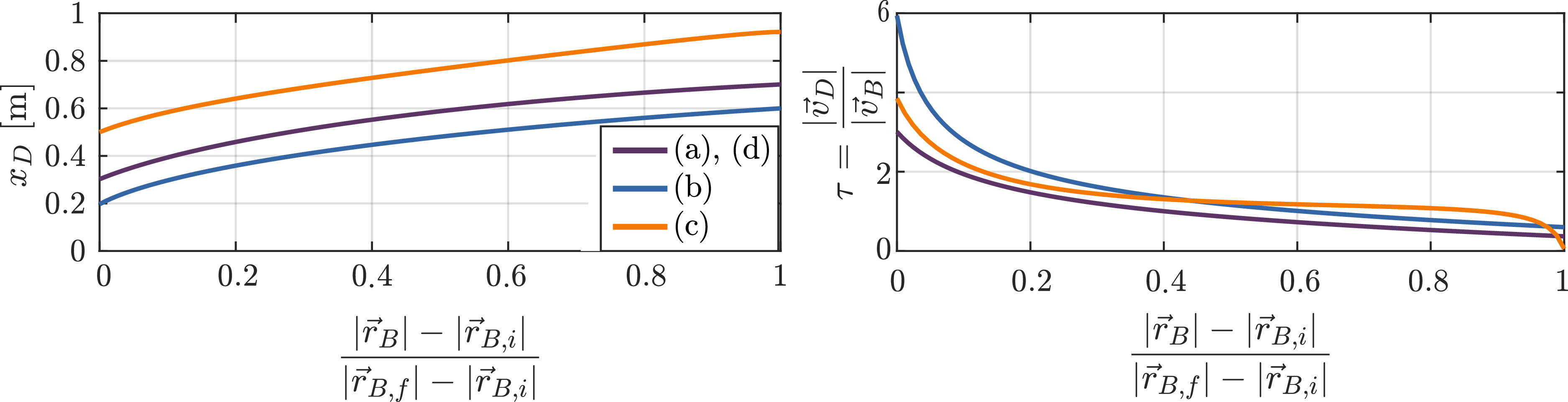
In Figure 3, the stroke of point
 $\mathrm{D}$
along
 $\hat {x}$
is computed as a function of the normalized actuator elongation, where
 $\vec {r}_B$
is the position vector of
 $\mathrm{B}$
in
 $\lt \hat {x}, \hat {y}\gt$
reference frame. Since the
 $x_D$
laws for the Scott–Russell and the translating link mechanism overlap, only a single solid blue line is used to describe both solutions. The figure also shows the instantaneous transmission ratio of the selected geometries, that is here defined as:
 \begin{equation} \tau = \displaystyle \frac {|\vec {v}_D|}{|\vec {v}_B|} \end{equation}
Please notice the subscript notation
 $[\ ]_{i,f}$
is used to refer to the initial and final mechanism configuration during the track adjustment, respectively. The results clearly underline how the Hoeken linkage is marked by a higher horizontal encumbrance, while on the other hand, both the Scott–Russell and the scissor mechanism prove to be quite compact along both
 $\hat {x}$
and
 $\hat {y}$
axis. Moreover, the Scott–Russel mechanism presents a more promising
 $\tau$
behavior. For these reasons, and for its relatively simplicity, the Scott–Russel mechanism has been chosen for adjusting the track width.
Point
 $\mathrm{D}$
stroke along
 $\hat {x}$
and transmission ratio diagram as a function of the normalized actuator elongation.

Figure 3. Long description
The image contains two line graphs side by side. The left graph shows the point stroke along the y-axis in meters and the normalized actuator elongation along the x-axis. Three lines labeled (a), (b), and (c) represent different data sets, with (a) and (d) overlapping in purple, (b) in blue, and (c) in orange. The right graph displays the transmission ratio along the y-axis and the same normalized actuator elongation along the x-axis. The same three lines from the left graph are present here as well. The graphs illustrate how the point stroke and transmission ratio change with varying actuator elongation, providing insights into the performance characteristics of the system.
Track adjustment mechanism final design.

Figure 4. Long description
The diagram illustrates a track adjustment mechanism final design. It features a drive motor connected to a series of links and hinge joints. The drive motor is attached to hinge joint A0, which connects to link A. Link A is connected to hinge joint B, which in turn connects to a linear guide. The linear guide is attached to hinge joint B’, which connects to link C. Link C is connected to hinge joint A, which further connects to hinge joint C’. Hinge joint C’ is attached to link D, which is fixed to the wheel steering axle. The diagram also includes a schematic representation of the mechanism’s movement and connections, showing the relationships between the different components.
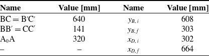
Figure 4 displays a visualization of the final design of the track adjustment mechanism, based on the Scott-Russel four bar linkage previously discussed. To enhance structural rigidity, the mechanism is constructed on two parallel planes, with exceptions for specific elements such as the actuation subsystem and links C and D. The mechanism is actuated by a linear guide (SHT-12, IGUS, Germany), with its lead screw powered by a NEMA 23 stepper motor. Additionally, utilizing the traction power of the tires is possible to assist in the track reconfiguration. In Table II, additional details about the mechanism links length are reported. The track adjustment mechanism enables AGRIMARO.Q to transition from the closed to the open configuration in approximately 18 s, achieving a positioning accuracy on the order of a few microns. Specifically, the NEMA 23 stepper motor and its driver ensure a screw positioning resolution of 0.5 µm per microstep. Taking into account the variable transmission ratio of the Scott–Russell mechanism, as shown in Figure 3, the final positioning accuracy at the wheel ranges from approximately 0.3 µm in the fully open configuration to 1.5 µm in the fully closed configuration.
3. Platform kinematic model
This section presents the kinematic model of the base platform of AGRIMARO.Q. Both in remote-controlled mode and autonomous mode, the kinematic model is essential to control the robot motions. In particular, inverse kinematics is needed to compute the reference values for the degrees of actuation once the desired velocities are known, and forward kinematics is needed to compute odometry from the current state of the actuators.
Track adjustment mechanism specifications.

From a functional point of view, the base of the robot can be modeled as a rigid body suspended on three swerve-drive units as shown in Figure 5. The swerve drive units are placed at the vertex
 $P_1$
,
 $P_2$
, and
 $P_3$
of a triangle. A frame rigidly connects the units
 $P_1$
and
 $P_2$
with parts of the track adjustment mechanism, namely the revolute joint
 $A_0$
and the linear joint connected to
 $B$
. The latter drive unit,
 $P_3$
, corresponds to the point D of the straight line mechanism. This enables the linear displacement of
 $P_3$
relative to the robot frame to adjust the robot track
 $t$
within the range
 $[800,\, 1200]$
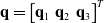
mm. Let us define the state vector for each swerve-drive unit as
 $\mathbf{q}_i = \begin{bmatrix} \delta _i & \dot {\theta }_i \end{bmatrix}^T$
, where
 $\delta _i$
is the steering angle, while
 $\dot {\theta }_i$
is the angular velocity of the wheel. Therefore, the robot actuation vector is
 $\mathbf{q} = \begin{bmatrix} \mathbf{q}_1 & \mathbf{q}_2 & \mathbf{q}_3 \end{bmatrix}^T$
.
AGRIMARO.Q kinematic model within the
 $\lt \hat {i} , \hat {j} \gt$
plane with respect to the fixed reference frame
 $\{s\}$
. Reference frame
 $\{b\}$
is attached to the robot chassis in point
 $O$
.

Figure 5. Long description
The kinematic model illustrates an agricultural robot within a fixed reference frame. The model includes various labeled points and vectors, such as P1, P2, P3, and their respective positions and directions. The fixed reference frame is attached to the robot chassis at point O. The diagram shows the relationships and movements between these points, including angles and vectors like δ1, δ2, δ3, and φ. The track adjustment mechanism is also depicted, highlighting components such as A, B, C, and D, and their interactions within the system.
Under the assumption of planar motion, hat is, no linear motion along
 $\hat {k}$
and no rotations along
 $\hat {i}$
and
 $\hat {j}$
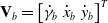
are permitted. Thus, the robot chassis motion can be described by the space velocity twist vector
 $\mathbf{V}_b = \begin{bmatrix} \dot {\gamma }_b & \dot {x}_b & \dot {y}_b \end{bmatrix}^T$
, expressed in the body frame
 $\{b\}$
. Under the assumption of pure rolling contact between the wheel
 $i$
and the ground, the velocity of the attachment point
 $P_i$
can be expressed as:
 \begin{equation} \dot {\mathbf{p}}_i = \dot {\theta }_i\hat {\mathbf{e}}_i \times r\hat {\mathbf{k}} = r\begin{bmatrix} \cos {\delta _i} \\ \sin {\delta _i} \end{bmatrix} = {\mathbf{s}_i} \, {(\delta _i)} \dot {\theta }_i \end{equation}
The same point velocity can be evaluated from the space velocity twist
 $\mathbf{V}_b$
as:
 \begin{equation} \dot {\mathbf{p}}_i = \begin{bmatrix} \dot {x}_b \\ \dot {y}_b \end{bmatrix} + \dot {\gamma }_b\hat {\mathbf{k}} \times \mathbf{p}_{P_i} = \begin{bmatrix} \dot {x}_b - y_i \dot {\gamma }_b \\ \dot {y}_b + x_i \dot {\gamma }_b \end{bmatrix} = \begin{bmatrix} y_i & 1 & 0 \\ \dot {x}_b & 0 & 1\end{bmatrix} \begin{bmatrix} \dot {\gamma }_b \\ \dot {x}_b \\ \dot {y}_b \end{bmatrix} = h_i \mathbf{V}_b \end{equation}
where
 $\mathbf{p}_{P_i} = \begin{bmatrix} x_i & y_i \end{bmatrix}^T$
is the position vector of the attachment point of the
 $i$
-th swerve drive unit expressed in the mobile frame
 $\{b\}$
. Hence, by considering the entire system, the following relationship can be written:
 \begin{equation} \begin{bmatrix} \mathbf{s}_1 (\delta _1) \\ \mathbf{s}_2 (\delta _2) \\ \mathbf{s}_3 (\delta _3) \end{bmatrix} \begin{bmatrix}\dot {\theta }_1 \\ \dot {\theta }_2 \\ \dot {\theta }_3 \end{bmatrix} = \begin{bmatrix} 0 & 1 & 0 \\ w/2 & 0 & 1 \\ 0 & 1 & 0 \\ -w/2 & 0 & 1 \\ t & 1 & 0 \\ 0 & 0 & 1 \end{bmatrix}\mathbf{V}_b \quad \Leftrightarrow \quad S(\mathbf{\delta }) \dot {\mathbf{\theta }} = H \mathbf{V}_b \end{equation}
The matrix
 $H$
depends only on the location of the swerve-drive units with respect to the
 $\{b\}$
frame, while the matrix
 $S(\mathbf{\delta })$
is state-dependent. In fact, for swerve-drive systems, it is impossible to derive a linear transformation that maps the actuation vector
 $\mathbf{q}$
into the velocity twist of the system
 $\mathbf{V}_b$
.
It is worth noting that the robot has three degrees of freedom and six actuation variables, thus three kinematic constraints must exist among the six actuation variables. In other words, the actuation variables must be chosen on a three-dimensional surface in the six-dimensional actuation space to fulfill both the pure rolling constraints and the rigid-body assumptions. These constraints can be written in the form:
 \begin{equation} \forall \,i \neq j, \quad \dot {\mathbf{p}}_i^T (\mathbf{p}_i - \mathbf{p}_j) = \dot {\mathbf{p}}_j^T (\mathbf{p}_i - \mathbf{p}_j) \end{equation}
From Eq. (4), the forward kinematic equation can be written as:
 \begin{equation} \mathbf{V}_b = H^\dagger \,S(\mathbf{\delta })\,\dot {\mathbf{\theta }} \end{equation}
where
 $H^\dagger$
is the pseudo-inverse of the
 $H$
matrix. Therefore, given the actuation variables
 $\mathbf{\delta }$
and
 $\dot {\mathbf{\theta }}$
, it is possible to compute the velocity twist of the system. It is important to underline that the actuation variables
 $\mathbf{\delta }$
and
 $\dot {\mathbf{\theta }}$
must be chosen according to the kinematic constraint Eq. (5). In the same way, the relation between the velocity twist
 $\mathbf{V}_b$
and the wheels speed
 $\dot {\mathbf{\theta }}$
can be written as:
 \begin{equation} \dot {\mathbf{\theta }} = S^\dagger (\mathbf{\delta })\,H\,\mathbf{V}_b \end{equation}
Nevertheless, Eq. (7) does not represent the inverse kinematics of the system, since the matrix
 $S$
is state dependent. A practical way to solve the inverse kinematics of the system is to consider each locomotion unit independently. Given the desired velocity twist, the velocity
 $\dot {\mathbf{p}}_i$
of point
 $\mathbf{p}_i$
can be evaluated through Eq. (3) (i.e.,
 $\dot {\mathbf{p}}_i = [\dot {x}_i, \dot {y}_i] = h_i \mathbf{V}_b$
). The norm of the velocity vector can be computed as
 $\|\dot {\mathbf{p}}_i\| = \sqrt {\dot {\mathbf{p}}_i^T \dot {\mathbf{p}}_i}$
and, therefore, the actuation variables associated to the locomotion unit
 $i$
can be evaluated as:
 \begin{equation} \begin{cases} \delta _i = \text{atan2}\left (\dot {y}_i / \|\dot {\mathbf{p}}_i\|, \dot {x}_i / \|\dot {\mathbf{p}}_i\| \right ) + k \pi ; \qquad k \in \mathbb{N} \\ \dot {\theta }_i = (\!-1)^{k}\, \|\dot {\mathbf{p}}_i\|/r \end{cases} \end{equation}
Thus, for
 $\delta _i \in [\!-\pi , +\pi ]$
, there are two possible solutions to the inverse kinematic problem for each swerve-drive system. This is in accordance with the physics of the system: the velocity of the center of the wheel is the same if the wheel turns
 $180^\circ$
around the vertical steering axis and it spins in the opposite direction.
Based on this model, the authors proposed a study on the achievable body twists if wheel speed limitations are considered, discussing the advantages and disadvantages of this type of locomotion. On this matter, the work [Reference Colucci, Botta, Tagliavini, Baglieri, Duretto and Quaglia6] is suggested to the interested reader.
4. Electrical and electronic system design
This section outlines the motion control system of AGRIMARO.Q. In general, a mobile robot control system can be classified into two parts: low-level and high-level control systems. The low-level control system manages the robot’s motion, while the high-level control system integrates all navigation algorithms necessary to enable autonomous driving. The high-level control system of AGRIMARO.Q is still under development and will be presented in future publications. In this section, an overview of the low-level control system is presented.
The low-level control system is designed to address the following functions:
-
• manage the power supply from the battery to the motor drivers and logic-level circuits;
-
• process input signals from the remote radio controller (manual mode), or the high-level onboard PC (autonomous mode);
-
• compute the inverse velocity kinematics of the base platform to determine the reference values for actuated variables, ensuring the desired velocity twist is achieved;
-
• monitor the platform’s current state using encoders on the steering shafts and hall-effect sensors on the traction wheels;
-
• execute precise control of the actuated degrees of freedom through closed-loop mechanisms, minimizing the deviation between the platform’s current state and the reference values for actuated variables;
-
• control the track adjustment mechanism.
Schematic representation of the electronic control system.

Figure 6. Long description
The diagram illustrates the electronic control system for a robotic vehicle, featuring both manual and autonomous modes. In manual mode, a user operates a radio controller that communicates with a radio receiver connected to a microcontroller. The microcontroller interfaces with various drivers, including B L D C drivers for traction and steering motors, stepper drivers for steering motors, and an L G driver for a linear guide. Each driver is linked to corresponding motors and encoders, with hall effect sensors for the traction motors. The linear guide includes a motor encoder, transmission, and limit switches. In autonomous mode, a PC communicates serially with the microcontroller, which also connects to an I M U for inertial measurement. The microcontroller manages communication buses for peripheral devices, including I 2 C, S P I, and C A N. The system integrates three swerve-drive units and one linear guide unit, each with specific components for motor control and feedback.
Figure 6 provides a schematic overview of the low-level control system, which is built around a USB-based microcontroller development unit – the Teensy 4.1 board by PJRC. Remote control signals are captured by an RC receiver and read by the microcontroller using the SBUS protocol. As illustrated in Figure 7, the initial implementation of AGRIMARO.Q utilizes seven of the sixteen available channels on the radio controller. Three switches control the operational modes:
-
•
 $L_2$
enables or disables the traction and steering motors;
-
•
$R_2$
toggles between omnidirectional mobility, sets the steering angles for track adjustment, or enables the linear guide motor while disabling the traction and steering motors; -
•
$L_1$
opens and closes the track adjustment mechanism.


Radio controller layout.

Figure 7. Long description
The image shows a remote control layout for an agricultural robot. The remote control has two joysticks labeled Lx, Ly, and Rx, Ry, with specific functions for each. The left joystick controls the left track mechanisms, with options to disable or enable traction and open, hold, or close the track mechanisms. The right joystick controls the right track mechanisms, with options for omnidirectional mobility, track mechanism mode, and specific angle settings. The user operates the RC transmitter, which sends signals to the RC receiver. The receiver processes the signals through an SBUS and a microcontroller (µC) to control the robot’s movements and functions.
When omnidirectional mobility is active, the right stick’s
 $R_x$
and
 $R_y$
axes determine the magnitude and direction of the linear velocity vector
 $\dot {\mathbf{p}}$
. Meanwhile, the left stick’s
 $L_y$
axis generates the reference value for the yaw angular speed
 $\dot {\gamma }_b$
, as shown in Figure 8. In this way, the desired velocity twist of the robot is defined, and the reference signals for the actuators can be computed using Eq. (8).
Algorithm to generate the reference signals from the radio controller inputs.

Figure 8. Long description
The equation begins with a vector containing R sub x, R sub y, and L sub y. This vector is processed through a series of functions to calculate the magnitude of the vector p, the angle phi using the arctangent of R sub y over R sub x, and a function applied to L sub y. The resulting components are x dot b, y dot b, and y dot b, which are calculated using the magnitude of p, the cosine and sine of phi, and the function applied to L sub y. These components are then input into a function labeled ikine eq 8, which outputs a vector containing delta 1, delta 1 dot, delta 2, delta 2 dot, delta 3, and delta 3 dot. This output is labeled ref and is used for actuators control.
Based on these reference values, closed-loop velocity control is applied to the traction wheels using feedback from Hall-effect sensors, while closed-loop angular position control adjusts the steering angles, as shown in Figure 6.
The
 $\mu$
Controller is also connected to the onboard PC for future implementation of autonomous navigation capability and to other communication buses to integrate tools and additional sensors.
5. Preliminary validation tests
This section presents several validation tests aimed at ensuring the reliability of AGRIMARO.Q in real-world operating conditions and evaluating its performance under various scenarios.
The three-wheeled robot has a mass of
 $117$
kg. The projection on the ground of its center of gravity with respect to
 $\{b\}$
is located at
 $\mathbf{p}_g = \begin{bmatrix}47.0 & -300.8\end{bmatrix}^T$
mm in the closed track configuration and at
 $\mathbf{p}_g = \begin{bmatrix}8.5 & -441.0\end{bmatrix}^T$
mm in the fully opened track configuration. Thus, it can be observed that, in the closed configuration, the second and third wheels bear slightly more load than the first one due to the position of the track adjustment mechanism. Specifically, the first wheel supports only
 $26 \%$
of AGRIMARO.Q’s total load, while the second and third wheels bear
 $36\%$
and
 $38\%$
, respectively. In the open track configuration, the load distribution becomes more balanced, with the first wheel supporting
 $31\%$
, the second
 $32\%$
, and the third
 $37\%$
of the total weight.
The tests focused mainly on the robot’s navigation and energy consumption. The main objective was to assess AGRIMARO.Q’s behavior and evaluate its power demand during typical operations. In particular, five different test scenarios were analyzed, reflecting the various tasks the robot can perform in greenhouses:
-
• Idle condition (ID), where the robot remains stationary;
-
• Longitudinal translation at maximum constant speed (LMS);
-
• Transition from one row to the next through continuous translation (CT);
-
• Transition from one row to the next through stepwise translation (ST), where steering and traction motor activation phases are separated;
-
• Transition from one row to the next through a classical turning maneuver (TM), in which the robot maintains a consistent front-facing orientation;
-
• Track adjustment operation (TA).
To analyze the robot power flow, the power sensor HO25-NMN by LEM Sensors was used to measure the battery voltage and the discharge current supplying the entire system, with data recorded at 10 Hz.
5.1. Idle tests
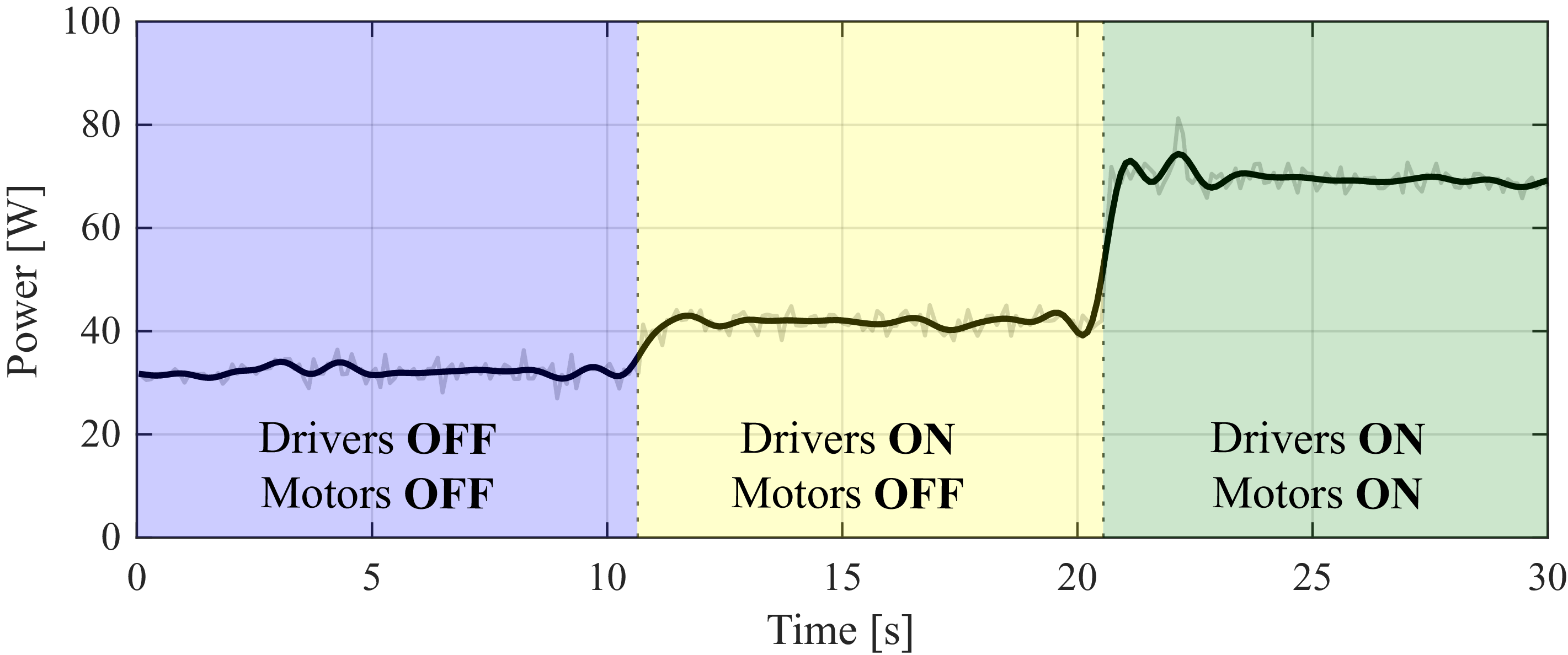
First of all, the ID scenario was considered, in which the robot remained stationary under three different conditions: drivers switched off, motors off, and motors on. Each condition was tested for about 10 s, as shown in Figure 9. All the data of the Preliminary Validation Tests have been filtered with a second-order Butterworth low-pass filter with sampling frequency of 10 Hz and cutoff frequency of 1 Hz.
Absorbed power during ID test, respectively, with drivers and motors switched off, drivers switched on and motors off and finally with both switched on.

Figure 9. Long description
The line graph displays absorbed power in watts over a time period of 30 seconds. The x-axis represents time in seconds, ranging from 0 to 30 seconds. The y-axis represents power in watts, ranging from 0 to 100 watts. The graph is divided into three distinct sections. The first section, from 0 to 10 seconds, shows the state where drivers are off and motors are off, with power levels around 40 watts. The second section, from 10 to 20 seconds, shows the state where drivers are on and motors are off, with power levels remaining around 40 watts. The third section, from 20 to 30 seconds, shows the state where both drivers and motors are on, with power levels increasing to around 70 watts. The graph includes two lines: a black line representing filtered data and a gray line representing raw data. All values are approximated.
As expected, a progressive increase in power consumption was observed when transitioning from one condition to the next, with a more significant step when the motors were switched on. Specifically, when both the drivers and motors were off, the average power consumption was
 $32.2$
W. This increased to
 $41.8$
W when only the drivers were active, and finally, due to the high power demand of the steering stepper motors, the power consumption rose to
 $69.3$
W.
5.2. Navigation tests
Then, the robot’s navigation capabilities were analyzed on three different terrains representative of its potential working environment: cobblestones (C), grass (GA) and gravel (GR). For each terrain, all the different scenarios mentioned before, except the ID one, were examined, and all tests were conducted in the closed configuration of the track mechanism.
In the LMS scenario, AGRIMARO.Q was driven in a straight line for 10 m at its maximum speed of
 $2.0$
m
 $/$
s. The power consumption was found to be relatively similar across the three different surfaces, with a higher average value on cobblestones, where it reached
 $94.5$
W. On grass and gravel, despite their higher friction, the average absorbed power was slightly lower, around
 $90$
W. This counterintuitive result is mainly due to the fact that, unlike the other terrains, the cobblestone surface has small slopes, causing additional transient efforts that increase power demand.
In the remaining scenarios, the objective was to simulate typical gantry robot operations in a greenhouse, specifically movement along a row and the transition to the next. For the CT, ST, and TM test scenarios, the robot was first driven for
 $10$
m in a straight line, then moved sideways to simulate the row change, and finally driven back another 10 m, at an average speed of
 $0.5$
m
 $/$
s. This test was repeated for each type of terrain. As briefly explained above, in the TM test, the robot rotated to enter the new row, thus maintaining its front orientation. In the CT test, the robot translated with a continuous motion to enter the new row, while in the ST test, the translation was split into three straight-line movements, stopping at each change in direction. Figures 10 and 11, respectively, compare different movement strategies on the same terrain and the same movement across different terrains. The results are shown only for grass and TM test scenarios, as this combination is expected to be the most used.
Absorbed power during navigation tests on grass (Raw data in transparency).

Figure 10. Long description
The line graph displays absorbed power during navigation tests on grass. The x-axis represents time in seconds, ranging from 0 to 60 seconds, while the y-axis represents power in watts, ranging from 0 to 200 watts. Three data lines are shown: one for continuous translation, one for stepwise translation, and one for turning maneuver. The continuous translation line is depicted in green, the stepwise translation line in black, and the turning maneuver line in yellow. The graph illustrates the power fluctuations over time for each type of robotic platform movement. All values are approximated.
TM tests (turning maneuver): (a) Absorbed power on the different terrain (Raw data in transparency); (b) Trajectory; (c) Photo of the setup.

Figure 11. Long description
The image contains three elements: a graph, a diagram, and a photo. The graph displays absorbed power on different terrains over time, with three lines representing different conditions. The diagram shows the trajectory of the robot during the turning maneuver, with numbered positions indicating key points along the path. The photo depicts the actual setup of the robot performing the maneuver in an outdoor environment, with numbered positions corresponding to those in the diagram. The robot is a wheeled rover designed for agricultural tasks, demonstrating its maneuverability and adaptability to various terrains.
On the grass, the CT and TM tests showed similar absorbed power levels, with average values of
 $117.9$
W and
 $119.1$
W, respectively. However, the TM took 15 s longer to complete the movement, as the robot needs to invert its orientation with respect to the row. The ST test was both the slowest, since the robot stopped each time it steered its wheels, and the one with the highest power peaks due to the formation of furrows in the ground that occurred mainly when steering the motorwheels in place. Nevertheless, ST exhibited the lowest average power consumption (
 $102.8$
W), as traction and steering motors were never operated simultaneously.
On cobblestones, an additional test was performed on a
 $15^\circ$
ramp at a speed of
 $1.5$
m
 $/$
s, including both ascent and descent phases. During the descent, the robot’s average power consumption was
 $87.1$
W, while in the ascent phase, it increased to
 $102.5$
W. As previously observed, the robot’s average power consumption on a flat cobblestone surface was
 $94.5$
W, which closely matches the mean value between the ascending and descending phases. This consistency suggests the validity of the measurements and supports the coherence of the results.
5.3. Track adjustment operation tests
Power consumption tests.

TA (track opening from
 $t=800$
mm to
 $t=1200$
mm) tests: (a) Absorbed power on the different terrains (Raw data in transparency); (b) Photo of the setup.

Figure 12. Long description
The image contains two distinct elements: a graph and three photos of a robotic platform. The graph displays power absorption over time for different terrains, with three lines representing different test conditions: TA-GA in green, TA-GR in blue, and TA-C in red. The x-axis represents time in seconds, ranging from 0 to 18 seconds, while the y-axis represents power in watts, ranging from 0 to 120 watts. The three photos show a robotic platform with a scissor-lift design, captured at different time intervals. The platform is equipped with wheels and appears to be performing tasks on a cobblestone surface. The photos illustrate the robot’s movement and interaction with the environment over time.
Finally, the TA test was performed and, similar to the navigation tests, it was repeated on each terrain. Figure 12 illustrates the track opening phase, which lasted
 $18$
s and exhibited the same power consumption across all terrains, with an average value of about
 $52$
W. The power trend showed a slight initial increase, due to a small peak in the speed required to initiate the opening motion, after which it remains almost constant until completion.
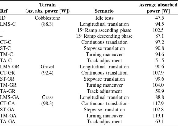
All the results of the power consumption tests are summarized in Table III. The TA test presents a different average power consumption value compared to Figure 12, as the table considers the entire track adjustment motion. This includes the initial
 $90^\circ$
rotation of the third wheel to align with the widening direction, the opening phase, the closing phase, and the final
 $-90^\circ$
rotation to restore its longitudinal orientation. Specifically, the average power consumption for the TA-GA test is
 $63.1$
W, which is higher than in the TA test on other terrains, likely due to the formation of furrows caused by wheel steering.
As expected and as already highlighted, AGRIMARO.Q requires more power on grass due to the ground softness, which cause the wheels to sink during motion. Indeed, considering the five different test scenarios, the average power consumption on grass is
 $98.3$
W, whereas on gravel and cobblestones, it is
 $92.4$
W and
 $88.3$
W, respectively.
Instead, focusing on row transition maneuvers, the TM tests proved to be the most power demanding. However, the choice between TM, CT, and ST should not be based solely on execution speed and power consumption but rather on the specific task the robot needs to perform and whether maintaining its front orientation is required.
To conclude, interestingly, the power consumption in idle conditions, with both drivers and motors on, was higher than during track widening. This result can be explained by the fact that, when stationary with the motors activated, all six navigation motors remain powered, including the three stepper motors responsible for steering, which have a higher power demand. In contrast, during track opening, the robot was programmed to disable all motion motors and power only the stepper motor controlling the linear guide.
6. Conclusion
This paper presented the development and testing of AGRIMARO.Q, an omnidirectional, three-wheeled mobile robot designed for precision agriculture operations in protected cultivation environments. The robot features a triangular gantry structure supported by three swerve-drive units, each positioned at a vertex of the triangle. Additionally, to adapt to different crop dimensions, AGRIMARO.Q has a track adjustment mechanism that enables the linear translation of one wheel. Specifically, this mechanism is based on the Scott–Russell linkage, with the orientation of the ternary element fixed using a parallelogram mechanism. This mechanism allows the track-width to be adjusted in a precise and mechanically robust manner, while minimizing the footprint of the mechanism along both the x and y axes. Its compactness ensures that it does not interfere with the area designated for future tool or sensors integration, making it highly suitable for greenhouse operations, where space optimization is critical. Preliminary validation tests confirmed the effectiveness of the proposed design. The track width can vary between
 $800$
mm and
 $1200$
mm within a maximum reconfiguration time of
 $18$
s, providing AGRIMARO.Q with high versatility and adaptability across a wide range of crop layouts. The positioning resolution, ranging from
 $0.3$
 $\mu$
m to
 $1.5$
 $\mu$
m depending on the transmission ratio, ensures precise and repeatable movement, enabling the robot to operate safely between narrow crop rows without risk of contact with plants. Moreover, the adjustable track improves both maneuverability in confined spaces and stability in wider environments. The design choice of using only three steering drive units instead of four is closely linked to the objective of reducing the overall weight of the rover compared to similar platforms, as well as lowering the torque required by the motor responsible for the track-widening mechanism. Additionally, having only three points of contact with the ground, which always lie on a plane, minimizes the need for a suspension system, especially considering the relatively low irregularity of greenhouse terrain.
This study also presented the robot’s motion control. The kinematic model was derived to establish the relationship between the robot’s velocity twist and the actuation variables. Then, the low-level control system was introduced. Finally, AGRIMARO.Q performance and power consumption were evaluated under real-world operating conditions while performing various typical tasks, including navigating different terrains and following the same trajectory using continuous or ST, as well as TMs. The results showed the robot’s ability to successfully adapt to different scenarios and different task requirements.
Further improvements could be achieved by completing the development of the high-level control. Specifically, several proprioceptive sensors should be added onboard AGRIMARO.Q to adapt the control system based on the surrounding environment, and to completely enhance its capabilities, the algorithms necessary for autonomous driving should be implemented.
Author contributions
LT, AB, and FA conceived and designed the study. LT, AB, and FA conducted data gathering. LT and GC derived the kinematic model. LT and FA wrote the article and AB, GC, and GQ revised it.
Financial support
This work was supported by the National Center for the Development of New Technologies in Agriculture (Agritech https://agritechcenter.it/) and by the European Union NextGenerationEU under the research program “PNRR MUR Missione 4, Componente C2, Investimento 1.1 NextGenerationEU - PRIN 2022” Figure 5 Real-Time Longitudinal Slip estimation on representative types of greenhouse terrains: Tiles, Grass, Firm Soil with Loose Gravel.Project title: FArmer robots: safe, sustainable and efficient precision agriculture in highly Challenging Environments (FACE) (Grant N. 2022EA5NT3, CUP D53C24004010006, D53C24004010006).
Competing interests
The authors declare no conflicts of interest exist.
Ethical approval
Not applicable.


 CC′D
 D
 x^
 D
 x^



 {s}
 {b}
 O






 t=800
 t=1200


