I. INTRODUCTION
Sandwich structures are characterized by thin walled face sheets or skins, bonded to a lightweight core, placed or sandwiched in-between the skins. The fundamental concept of a sandwich design is based on the separation of functions. Thereby, the skins are responsible for taking over the in-plane tensile and compressive stresses, whereas the core has to carry the shear stresses. By selecting high strength and modulus materials, like carbon fiber reinforced polymer (CFRP), for the skins, and highly porous, lightweight cores, like honeycomb-type paper structures, very efficient and therefore extremely lightweight panel structures can be realized.
Sandwich structures are used in various application areas, especially in aerospace, but are also very common in transportation and automotive, ship building, architecture, building and construction industries as well as in furniture industry, and are well known in daily life from corrugated board boxes in packaging.
Sandwich structures based on skins made of glass or C fiber reinforced polymers and on cores like polymer foam, aramid paper honeycomb structures, or grid cores (GCs) based on bi- or multidirectional CFRP webs Reference Fan, Meng and Yang1 are well known. For high temperature applications, e.g., in sintering furnaces, sandwich structures made of monolithic ceramics, Reference Kollenberg2,Reference Van Voorhees and Green3 like alumina and cordierite, are enabling charging carriers with high loading capacities and low masses, leading to faster cycles for heating up and cooling down, reduced energy consumption, and more economic production processes. Typical applications for SiC based sandwich structures are highly rigid mirrors in aerospace. However, usually no separate cores are used, but ribbed structures are machined out of massive preforms and joined together, leading to hollow SiC structures with the ribs acting as webs. Reference Papenburg4
To decrease the wall thickness and weight, as well as to increase the damage tolerance and fracture toughness of structures made of monolithic ceramics, carbon fiber reinforced carbon (C/C), manufactured via chemical vapor infiltration (CVI), as well as ceramic matrix composite (CMC) have been used for the build-up of sandwich structures. Typical application areas for C/C sandwich panels are aircraft firewalls and satellite structures, like substructures for highly precise measurement devices. Due to their high stiffness and low or zero coefficient of thermal expansion (CTE), geometrically stable structures can be obtained, despite varying temperatures in space environment. Reference Fehringer, Andre, Lamarre and Maeusli5 Compared to C/C, CMC materials offer higher oxidation and abrasive resistance as well as lower particle emission due to the replacement of the C matrix by SiC. Sandwich structures, based on SiC/SiC and C/SiC skins and foam or lattice cores made of SiC or SiSiC, have been manufactured via CVI Reference Hurwitz6 or polymer infiltration and pyrolysis (PIP). Reference Ostertag, Haug, Renz and Zankl7 Typical application areas are acreage thermal protection systems (TPS) or actively cooled hot structures for spacecraft.
Using PIP, SiC/SiC skins were joined to SiC foam and lattice cores with a slurry, based on SiC particles and preceramic polymers. Subsequently, the sandwich preform was densified via repeated PIP, again using Si precursors. Reference Ortona, Pusterla and Gianella8,Reference Ferrari, Barbat, Esser, Petkov, Kuhn, Gianell, Barcena, Jimenez, Francesconi, Liedtke and Ortona9 Thereby, costly preceramic precursors were used and up to 5 PIP cycles were needed to obtain a CMC with sufficient matrix content and low open porosities in the range of 10%, finally leading to high overall manufacturing cost.
Due to high CTE mismatch, sandwich structures built up of C/SiC skins and SiSiC core structures could not be realized. Cracks and delaminations were observed in the core and between core and skins, respectively. To overcome the CTE problem, similar CMC materials should be used for the skins and the core, leading to an all-CMC design for C/SiC or C/C–SiC materials. Therefore, sandwich structures, entirely made of C/SiC via PIP, Reference Goodman, Nejhad, Wright and Welson10 as well as C/SiC and SiC/SiC honeycomb cores based on CVI, Reference Wright11,Reference Le12 have been developed for the use in optical benches or mirror substructures. Additionally, C/C–SiC foldcores (FCs) have been realized via liquid silicon infiltration (LSI). Reference Lengowski13
At DLR, the LSI process has been developed since the late 1980s. Reference Krenkel14 Due to short process cycle times and the use of low cost raw materials, like phenolic resins as the matrix precursor, the LSI method could open up new application areas for the CMC beyond aerospace. As an example, LSI based C/C–SiC and C/SiC are the materials of choice for brake discs and pads in automotive and industrial applications, which are representing the economically most important application area for the C fiber based CMC. Reference Heidenreich, Kütemeyer and Koch15
The LSI process is based on three main steps. In the first step, a CFRP preform is manufactured using well-known methods like warm pressing, autoclave technique, filament winding, or resin transfer molding (RTM), which have been adapted to the use of high-temperature resins offering high C yield after pyrolysis. In the second step, the CFRP part is pyrolyzed in an inert atmosphere. Thereby, the polymer matrix is transformed to a C matrix. Due to the volume shrinkage of the matrix, in combination with the geometrical stability of the C fiber preform, internal stresses are induced, leading to a 3D network of microcracks and a segmentation of the fiber tows into dense bundles of C/C. In the last process step, the resulting porous C/C preform is infiltrated with molten silicon by capillary forces. In parallel to the infiltration, the SiC matrix is built up by a chemical reaction of Si and C. The final C/C–SiC is a dense, multiphase material, characterized by load carrying C/C bundles, embedded in the SiC matrix with some residual Si. The resulting C/C–SiC materials offer reasonable mechanical performance (σtensile = 80–110 MPa; E = 50–70 GPa) and low open porosity (2–5%).
For complex structures, an in situ joining technology has been developed. Reference Krenkel, Henke and Mason16 Thereby, C/C subcomponents, which can be manufactured easily in the near net shape technique, are assembled by a slight pressure fit or by adhesive bonding, using a joining paste, based on phenolic resin and carbon powder. The joining itself is performed in situ, during the simultaneous siliconization of the joining paste and the C/C parts of the assembled structure. Thereby, the components are permanently bonded to an integral structure. Reference Kochendörfer, Krenkel, Evans and Naslain17
In a new approach, the advantages of the sandwich design principle were combined with the cost effective LSI manufacturing method. C/C–SiC sandwich structures based on two different C/C–SiC core types, FCs and GCs, could be realized by adapting the process parameters, especially for the manufacture of thin walled core materials and the in situ joining of filigree cores to the skins. Bending tests showed high bending strength and stiffness of specimens and were demonstrating the high potential for the use of C/C–SiC sandwich structures in various application areas, like optical benches, acreage TPS, and hot control surfaces for spacecraft, as well as for charging racks in high-temperature furnaces, e.g., used for the thermal treatment of metal parts, or for high temperature heat exchangers in actively cooled structures.
II. SPECIMENS MANUFACTURE
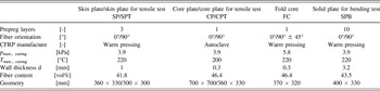
The CFRP preforms for plates and core structures were manufactured via warm pressing and an autoclave technique (Table I) using a resin preimpregnated fabric (prepreg), based on phenolic resin precursor, named JK 60 (Hexion Specialty Chemicals GmbH, Iserlohn, Germany) at DLR, and a 2D carbon fiber fabric (Toho Tenax HTA40, 3K, twill weave, 245 g/m2; Toho Tenax Europe GmbH, Wuppertal, Germany) as the raw material.
Overview of the CFRP preforms.

For the manufacture of the CFRP FC, one sheet of prepreg was placed in-between two release tapes and manually folded step-by-step, using a foldable master panel. Reference Gottschalk18 For final forming, the layup was put in a precise, 3D milled mold. After closing the mold, the layup was densified to a defined thickness by applying a uniform pressure of 5.8 kPa, and the prepreg was cured in a furnace (T max. = 220 °C, 4.5 h). Two types of FCs were manufactured, with the fibers oriented in 0°/90° and in ±45°, respectively. Therefore, the prepreg sheets were cut to size with appropriate fiber orientation.
In the second step, the CFRP preforms were pyrolyzed at T max. = 1650 °C in N2 atmosphere at ambient pressure. To prevent distortion and delamination, the preforms were loaded with graphite plates, ensuring a constant pressure of up to 1 kPa during the transformation of the polymer to carbon matrix. The FC preform was embedded in graphite granulate, and a graphite plate was placed on the top.
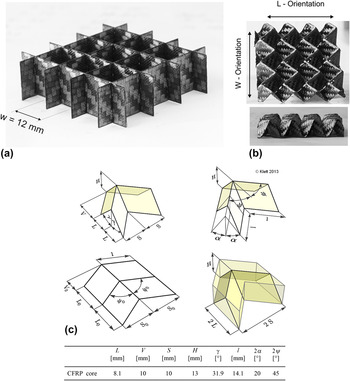
In contrast to the near net shape manufacture of FCs, GCs were built up by putting together a multitude of single C/C strips to a grid assembly, with the biaxial strips oriented in parallel and in perpendicular (0°/90°) to the bending specimens length (Fig. 1). Interlocking of the strips was enabled by equidistant slits, running from one side of the strip until the center line. Due to high precision laser cutting, tolerances of the slits width and distance could be minimized, leading to a tight fit of the strips and a geometrically stable C/C grid. Ten GCs (300 × 48 × 13 mm3) were manufactured by putting together 4 longitudinal strips (300 × 13 × 0.3 mm3) and 25 lateral strips (48 × 13 × 0.3 mm3) for each core. Laser cutting was done by the company Laseric, Stuttgart, with a pulsed fiber laser (v = 500 mm/s, 50 cycles; pulse: 26,500 Hz, 200 ns). Thereby, an overall cutting velocity of 10 mm/s was obtained and a set of 29 strips, needed for one core assembly, could be cut in less than 14 min.
(a) Exemplary grid and (b) FC (60 × 60 × 13 mm) with L and W directions indicated 18. (c) Nomenclature of FCs Reference Klett19 and geometry data of FCs manufactured.

For joining the C/C core and the skins, a joining paste, based on JK 60 and a defined content of carbon powder (Timrex® PC 40-OC, Timcal Deutschland GmbH, Düsseldorf, Germany), was used. In a first step, a layer of joining paste with constant thickness (3 mm) was applied onto a steel plate by using a doctor blade. The core structure was dipped into the joining paste layer, placed onto the first skin plate, and the joining paste was cured at T max. = 220 °C for 4 h. After joining the second skin, using the same process, the resulting C/C sandwich structure was siliconized. Thereby, a defined amount of Si granulate (PCL-NCS-1, 1–20 mm, Wacker Chemie AG, Munich, Germany) was placed on the top of the structure and heated up in a furnace (T max. = 1650 °C/P ≤ 2 mbar/1.5 h). During heating up, the polymeric content of the joining paste was converted to a C joining material, characterized by pores and microcracks. At temperatures beyond 1425 °C, the Si granulate melted and homogeneously infiltrated the microcrack system of the C/C structure by capillary forces. In parallel to the infiltration, the SiC matrix was built up by a chemical reaction of Si and C at the surfaces of the microcracks, finally leading to a dense and permanently joined C/C–SiC sandwich structure.
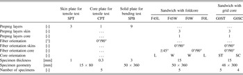
In order to determine the mechanical properties of the C/C-SiC skin and core material, five specimens (80 × 15 mm2) were cut out of SPT (skin plate for tension tests) and CPT (core plate for tension tests), respectively, using diamond coated tools. Five bending specimens (360 × 50 mm2) were cut out from the SPB (solid plate for bending tests), as well as from the FC based C/C–SiC panels in each of the two main directions (L, W) of the core. The GC based C/C–SiC sandwich samples (300 × 48 × 15 mm3) were not machined after siliconization, but cut and assembled to the final size before joining.
III. TESTING
The density and open porosity of the skin/core material were measured using the Archimedes method (DIN 51,918). For the sandwich specimens, density could be determined by measuring specimen weight, area, and volume. The Archimedes method was not applicable, due to excessive water remaining on the surface of the core structure, making the accurate measurement of wet mass impossible. The microstructure of the core as well as of the skin material was investigated using scanning electron microscope (SEM; Zeiss Gemini Ultra plus, Carl Zeiss Microscopy GmbH, Jena, Germany).
Tension strength and Young’s modulus for the skin and the core material were determined on coupons cut out of representative plates and tested in accordance to DIN EN 658-1 at ambient temperature using a universal testing machine (Zwick 1494, Zwick GmbH & Co. KG, Ulm, Germany; Table II). Thereby, strain was measured using strain gauges on both sides of the SPT coupons. For the thin walled CPT coupons, the adhesive, used for applying the strain gauges, influenced the mechanical behavior of the specimen. Therefore, no strain values could be determined on CPT. Reference Sleiman20
Overview of tested C/C–SiC specimens.

The sandwich as well as solid plate specimens were investigated in four point bending tests on the basis of DIN 53,293. The skin strain was determined by strain gauges (l = 6 mm), applied in the center of the bottom and top surfaces of the specimen. Ultimate bending moment M u (1), tension/compression stresses in the skins σu,skin (2), and shear stress of a representative, homogeneous core τu,core (3) were calculated according to DIN 53,293.
Additionally, the ultimate intralaminar shear stress τu,web GC (4) was analyzed for GCs. The initial tangent modulus and ultimate modulus were determined from stress strain curves between 5% and 15% and at 100% of the ultimate stress σu,skin, respectively. The contribution of the core structure to the overall sandwich stiffness was studied by comparing effective and theoretical stiffness. Thereby, the effective flexural stiffness EIeff. (5) was calculated on the basis of the measured ultimate bending force F u and the calculated deflection (f m, f s), whereas for the theoretical flexural stiffness EItheo. (6), only the material properties and the moment of inertia of the skins are considered. The relevant deflection f m − f s was calculated on the basis of the ultimate tensile strain, determined by strain gauges, the resulting elongation of the tension loaded bottom skin, and an assumed ideal circular deformation of the specimen in the area of L S. To investigate the influence of the slits in the GC, 5 bending tests with the slits located in the tension loaded, bottom side (G0ST) and 4 tests with the slits in the compression loaded, top side (G0SC) of the specimens were performed.
 $${M_{\rm{u}}} = {F \over 2} \cdot {L_{\rm{B}}} \cdot {10^{ - 3}}\left[ {{\rm{Nm}}} \right]$$
 $${\sigma _{{\rm{u}},{\rm{skin}}}} = \pm {{{M_{\rm{u}}} \cdot h} \over {I \cdot 2}} \cdot {10^3} = \pm {{{M_{\rm{u}}} \cdot h} \over {b \cdot {t_{\rm{s}}} \cdot {d^2}}} \cdot {10^3} = \pm {{{F_{\rm{u}}} \cdot {L_{\rm{B}}} \cdot h} \over {2 \cdot b \cdot {t_{\rm{s}}} \cdot {d^2}}}\left[ {{\rm{MPa}}} \right]\quad$$
 $${\tau _{{\rm{core}}}} = {{{F_{\rm{u}}}} \over 2} \cdot {1 \over {b \cdot d}}\left[ {{\rm{MPa}}} \right];\;{\tau _{{\rm{u}},{\rm{core}}}} = {3 \over 4} \cdot {{{F_{\rm{u}}}} \over {b \cdot d}}\left[ {{\rm{MPa}}} \right]\quad$$
 $${\tau _{{\rm{u}},{\rm{web}},{\rm{GC}}}} = {3 \over 4} \cdot {{{F_{\rm{u}}}} \over {n \cdot {t_{\rm{c}}} \cdot d}}\left[ {{\rm{MPa}}} \right]$$
 $${\rm{E}}{{\rm{I}}_{{\rm{eff}}{\rm{.}}}} = {{{F_{\rm{u}}} \cdot {L_{\rm{B}}} \cdot \mathop {{L_s}}\nolimits^2 } \over {16 \cdot \left( {{f_{\rm{m}}} - {f_{\rm{s}}}} \right)}} \cdot {10^{ - 6}}\left[ {{\rm{N }}{{\rm{m}}^2}} \right]$$
 $${\rm{E}}{{\rm{I}}_{{\rm{theo}}{\rm{.}}}} = E \cdot {{b \cdot {t_{\rm{S}}} \cdot {d^2}} \over 2} \cdot {10^{ - 3}}\left[ {{\rm{N}}{{\rm{m}}^2}} \right]$$

IV. RESULTS AND DISCUSSION
A. Properties of skin and core materials
Open porosity and density was similar for the C/C–SiC skin (SPT: e′ = 5.69%; ρ = 1.93 g/cm3) and core material (CPT: e′ = 8.92%; ρ = 1.84 g/cm3). SEM investigation showed the typical C/C–SiC microstructure, characterized by dense C/C bundles, embedded in the SiSiC matrix, in both, the three layers based SPT as well as in the one layer based CPT. Despite a similar fiber content in the CFRP preform (ϕf,SPT = 41.8 vol%; ϕf,CPT = 46.4 vol%), the skin material showed a higher tensile strength (σt,SPT = 73.9 MPa; σt,CPT = 49.4 MPa) compared to the core material. This was traced back to a higher conversion rate of the core material. In the three-layer composite of the skin material, parallel aligned fiber tows from adjacent fabric layers are able to merge locally, leading to large segments of dense C/C with a low surface to volume ratio. During siliconization, only the fiber filaments at the surface of these C/C segments were in contact with Si and were transformed to SiC. Si could not infiltrate the dense, merged C/C bundles and therefore most of the fiber filaments were well protected from Si attack and therefore were not converted to SiC. Due to the lack of adjacent fabric layers, merging of fiber tows was not possible in the single layer core material, resulting in an increased surface to volume ratio of the small C/C segments, finally leading to a higher conversion rate of the C fibers to SiC.
Stress/strain curves of SPT showed a nonlinear behavior, typical for C/C–SiC. The initial tangent modulus and ultimate modulus were 62.3 GPa and 45.3 GPa, respectively. For CPT, strain measurement was not possible, as described in chapter 4.
B. Microstructure of sandwich structures
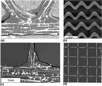
As observed in SPT and CPT plates, also the sandwich structures showed typical C/C–SiC microstructures, with most of the C fibers well protected from Si attack by the formation of dense C/C bundles, in both, the three-layer based skins as well as in the one layer based core (Fig. 2).
Joining of (a, b) FC and (c, d) GC to the skin. (a, c) SEM images of the cross section of the C/C–SiC sandwich structure, showing dense segments of C/C (dark gray) embedded in the SiSiC matrix (light gray) in the skins as well as in the cores. The joining area is characterized by C, SiC, and pores (black) and the meniscus formed by the joining paste is clearly visible. (b, d) The X-ray CT image of the joining area, showing a homogeneous distribution of the joining material.

During pyrolysis, the joining paste (polymer and C) was converted to a porous C, resulting in volume shrinkage of the joining material. Due to the geometrical stability of the C/C skins and core, internal stresses were built up, finally leading to microcracks in the joining material. During siliconization, the joining material was infiltrated by the Si melt and a thin layer of SiC was built up on the surfaces of the microcracks and pores. Remaining volumes in broad microcracks and large pores were filled up with Si. Additionally, pores were observed in the siliconized joining material, caused by the closed porosity in the carbonized joining paste, which was not accessible for the Si melt.
During the curing of the joining paste, a meniscus was formed due to interfacial tension, leading to an enlarged joining area at the skin as well as at the core interface. The joint of FCs was characterized by a large meniscus, formed in the angular contact zone of core and skin, and a joining width in the range of 3–5 mm. In the rectangular joint of the GC and the skins, a low amount of joining paste was observed, which led to the formation of a small meniscus and a low width of the joint of 1–2 mm. X-ray CT (X-ray computed tomography) investigation of C/C–SiC sandwich structures showed a uniform distribution of the joining material along the contact lines, and no voids were observed.
C. Failure modes of sandwich structures under bending
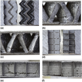
In 4 point bending, almost all FC based specimens showed skin failure mode (Fig. 3). However, in most cases, the fracture behavior was quite brittle, and therefore difficult to analyze. The first fracture was assumed to take place in tension loaded bottom skins, immediately followed by a sudden but locally limited fracture of the entire cross section of the sandwich structure. In some specimens, also a mixed failure mode with skin tension and compression failure as well as debonding of the joint between core and skin, or more precisely in the first layer of the skin, was observed. Two out of 20 specimens showed a shear failure of the core. Thereby, no complete fracture of the skins was observed. The fiber orientation in the core material, as well as the core orientation in the specimens did not influence the failure mode.
(a–c) FC and (d–f) GC based specimens after 4-point bending. (a, b) Skin tension failure of the FC based sandwich. (c) Shear failure in FC. (d) Skin tension failure of the GC based sandwich. (e) Debonding and core shear failure at the intersection combined with the quasi-ductile damage of the skins. (f) Core shear failure and crack stopped in the web.

The GC based specimens mainly failed in debonding and core shear mode, sometimes followed by skin failure (Fig. 3). The core webs oriented in parallel to the specimen length showed cracks, caused by shear stresses, in the area in-between the perpendicular webs as well as directly at the intersections. In the latter case, no crack propagation into web areas and a quasi-ductile damage behavior of the skins were observed. One out of 10 specimens showed skin failure mode and was cracked in the center of the specimen length. In any case of skin failure, the crack in the skin was located directly at, and in parallel to, the lateral webs.
D. Skin stresses and elastic moduli
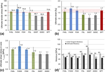
To determine the effectivity of the sandwich design, the mechanical properties of the skins, obtained by the bending tests of the sandwich specimens, were compared to the properties derived from the tensile test of SPT. For the different FC based specimens, flexural strength, which is the ultimate tensile stress in the bottom skin, was on a similar level as the tensile strength of the skin material (σu,FC = 71.2–85.9 MPa; σt,SPT = 73.9 MPa), whereas the strength of the GC based specimens was on a lower level (σu,GC = 57.3 MPa; Fig. 4). Ultimate strain was lowest for the GC based specimens (εf,G0ST = 1.06‰; εf,G0SC = 1.28‰) and F0L (εf,F0L = 1.32‰), and therefore 20–40% lower compared to the strain obtained in the tension test (εu,t,SPT = 1.69‰, Fig. 4). F45L and F0W showed an ultimate strain similar to the tensile strain of SPT, whereas for F45W, a slightly higher ultimate strain but also high scattering was observed (εf,F0W = 1.86 ± 0.49‰).
(a) Ultimate tensile stress and (b) tensile strain of C/C–SiC sandwich compared to the skin plate (SPT). (c) Ultimate shear stress in a homogenized representative core, determined by 4 point bending tests of C/C–SiC sandwich specimens. (d) Initial tangent and ultimate moduli of tension loaded skins of C/C–SiC sandwich specimens derived from 4 point bending and of SPT obtained by tensile test.

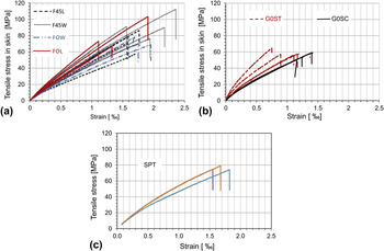
Generally, in the tensile test of solid coupons as well as in the bending test of the sandwich specimens, a nonlinear stress/strain behavior was observed (Fig. 5), characterized by a high initial tangent modulus and lower ultimate modulus. The stress/strain curves and moduli for the skins, derived from sandwich specimens, were similar to the behavior and values obtained by SPT. However, G0ST showed up to 40% higher initial tangent moduli compared to SPT, but also high scattering.
Tensile stress and strain in the skins of the C/C–SiC sandwich based on (a) FCs, (b) GCs, and (c) SPT.

E. Core shear stresses
Ultimate core shear stress was lowest for the GC based specimens (τu,core,GC = 1.1 MPa). For the FC specimens, ultimate shear stress was highest for cores oriented in the W-direction and a fiber orientation of ±45° in the core material (F45W), and lowest for the L direction and 0°/90° fiber orientation (F0L). The high shear stresses, obtained by the FC based specimens, were explained by the angular geometry of the FCs, leading to a conversion of the shear load to in-plane tensile and compressive stresses. In GC based specimens, the shear loads were converted to intralaminar shear stresses, which could be carried by the longitudinal webs, oriented in parallel to the specimen length, only. Considering the four longitudinal webs and the entire height of the core, an intralaminar shear stress in the GC webs of τu,web,GC = 42.4 MPa was obtained. In a worst case scenario, the webs were not joined at all at the intersections. This would lead to an increase of the ultimate shear stress to τu,web,GC = 84.7 MPa in the remaining, not slit half of the webs height at the intersections. Taking into account the shear strength of a typical multilayer C/C–SiC material (tu = 80 MPa Reference Hofmann, Öztürk, Koch and Voggenreiter21 ), this stress concentration would explain the observed shear failure of the core.
F. Sandwich stiffness
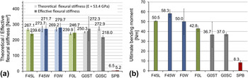
Effective flexural stiffness was in the range of 240 to 280 N m2 for the FC specimens (Fig. 6). G0ST showed higher stiffness combined with higher scattering (EIeff.,G0ST = 272.3 ± 77.0 N m2), compared to G0SC (EIeff.,G0SC = 218 ± 9.7 N m2). Taking into account the lower areal and volume mass of the GC based specimens (mA,GC = 4.2 kg/m2, ρGC = 0.28 g/cm3), compared to the FC specimens (mA,FC = 5.2 kg/m2, ρFC = 0.35 g/cm3), highest values for effective stiffness were obtained with G0ST, showing the potential of this core type for the manufacture of stiff sandwich structures. The high scattering was assumed to be caused by buckling of the thin walled longitudinal webs. F0W and F45W showed a 13% higher effective stiffness compared to specimens with the FC oriented in the L direction (F0L, F45L). No significant influence of the fiber orientation (0°/90° or ±45°) in the FC to the effective stiffness was observed.
(a) Theoretical and effective flexural stiffness and (b) ultimate bending moment of solid plate and sandwich structures based on FCs and GCs.

In most test series, effective and theoretical stiffness were similar, indicating a well-balanced sandwich design, with a low contribution of the core structure to the overall sandwich stiffness, but a proper stability of the core, ensuring a constant distance and moment of inertia of the skins, as well as a lightweight design. The slightly higher effective stiffness compared to theoretical stiffness (F0W, G0ST) is generally indicating high stiffness of the core structure, whereas in the opposite case, the lower effective stiffness (F45L: −9%, G0SC: −26%) was assumed to be caused by an instable or weak core with low shear and compression stiffness. Additionally, deviation in skin properties may be a reason for the differences between theoretical and effective stiffness, as well as for the deviations of the effective stiffness in each of the test series, and has to be further investigated.
G. Comparison to solid plate
Comparing the different designs on the basis of a similar area density, sandwich structures (5.7 kg/m2, h = 15 mm), offered significantly higher mechanical properties, compared to the thin walled, solid C/C–SiC panel SPB (5.5 kg/m2, t = 3 mm), as expected. Effective flexural stiffness of sandwich specimens was up to 54 times higher, and bending moment at fracture (Fig. 6) was up to 7 times higher compared to the solid specimens from SPB.
H. Comparison of FC and GC based sandwich structures
FC and GC based sandwich structures showed significantly different failure behavior and mechanical performance. This was due to the different properties of the core structures. In FCs, the webs were oriented in an angular geometry, acting as a lattice, and transforming the shear loads into in-plane tension and compression loads. In combination with the continuous fiber reinforcement, high structural core stiffness and core shear strength were obtained.
In contrast, GCs were characterized by straight webs, oriented perpendicular to the skins. Thereby, the shear loads were transformed to intralaminar shear stresses which could be carried by only one-half of the bidirectional webs, i.e., the longitudinal webs, oriented in parallel to the load direction. Additionally, the webs had to be slit at the intersections for assembly. Due to the fact, that no joining paste was used at the slits, the joining of the web intersections was insufficient, which halved the load carrying cross section of the webs at the slits, and finally lead to shear stresses well above the materials shear strength. Additionally, the GCs induced stress peaks, due to the sharp change in structural stiffness at the lateral webs, and a local increase of skin thickness, caused by the joining material of the lateral webs. In contrast, the angular design and the zigzag course of the joining lines of the FCs offered a more homogeneous load transfer between skin and core, compared to the straight joining lines of the GCs. Furthermore, using the FCs, a higher amount of joining paste was taken up, which lead to a larger joining area, and finally to higher shear strength, as well as out-of-plane tension strength, of the FC joint compared to the joint of the GCs.
Due to the resulting core shear and debonding failure at low bending loads, the mechanical performance, offered by the skins, could not be fully utilized in GC sandwich structures. Therefore, the ultimate stress and strain in the skins, as well as ultimate bending moment was lower compared to FC based structures, as well as lower as expected from the tensile properties of the skin material.
Effective flexural stiffness of FC and GC based sandwich specimens was on a comparable level. However, the stiffness of G0SC was on a lower level, compared to G0ST and FC based structures, which was explained by the slits located in the compression zone.
V. CONCLUSION
CMC sandwich structures were manufactured via the LSI process and in situ joining technology. Thereby, it was demonstrated that even very thin walled CFRP preforms based on a single layer of C fiber fabric and a wall thickness of 0.3 mm can be transformed to a typical C/C–SiC material by reactive melt infiltration. Compared to commonly used multilayer materials, the mechanical properties of single layer C/C–SiC decreased, due to an increased conversion of C fibers to SiC, but still offered a typical C/C–SiC behavior, characterized by reasonable strength, low modulus, and a damage tolerant, quasi-ductile fracture behavior.
Lightweight C/C–SiC core structures could be manufactured by a near net shape folding technology, as well as by assembling grid structures, using slit webs, cut out of C/C preform plates via laser beam. Despite small contact areas, especially for the line contact of the GCs, homogeneous and reliable joining of the filigree core structures to the skins could be achieved by a modified in situ joining technique, based on dip coating.
Four point bending tests showed that the selected sandwich design, with an overall thickness of 15 mm, a skin thickness of 1 mm, and a core density of 0.09 g/cm3 (90 kg/m3), was well balanced, and the mechanical properties of the skin material, like tension strength, ultimate strain, and elastic modulus, could be fully transferred to the sandwich structure, especially for the FC based structures. Flexural stiffness of different sandwich structures was on a comparable level. However, G0SC showed a lower stiffness, due to a weaker core structure with the web slits located in the compression zone. Because of the low shear strength of the GCs, the properties of the skins could not be fully utilized in the sandwich structures, and ultimate bending moment was lower, compared to the loads obtained with FC based sandwich specimens.
Despite these drawbacks, GC based sandwich structures were easy to manufacture and offered reasonable flexural stiffness, especially taking into account the 23% lower density compared to the FC based specimens. Both of the core types, FCs as well as GCs, are promising candidates for the development of highly stiff and lightweight C/C–SiC structures.
Future work will concentrate on the further development of lightweight FCs for increased sandwich thickness as well as on the improvement of shear strength of GCs. For the latter, webs with the fibers oriented in ±45° and improved joining methods for increased joint strength at the web intersections are in the focus.
Supplementary Material
To view supplementary material for this article, please visit https://doi.org/10.1557/jmr.2017.208.