Climbing the dimension ladder
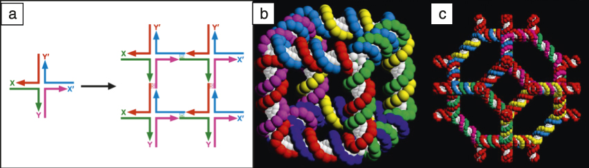
The basic notion of DNA nanotechnology requires two concepts—branched DNA and “sticky ends.” The ways in which the sequence of DNA strands could be designed, such that multiple strands could self-assemble into branched molecules rather than linear molecules, have been detailed. Reference Seeman1 Branched molecules are designed to contain three to 12 arms, Reference Seeman1 though the most commonly used branched molecules correspond to the four-arm Holliday junction recombination intermediate ( Figure 1a). Sticky ends are short, single-stranded overhangs that extend from the end of a double helical DNA molecule; they result from one strand being longer at that site than the other. They can pair with each other just like other DNA strands, but, as seen in Figure 1a, they control intermolecular interactions. As a consequence, it is possible to imagine assembling branched molecules into larger assemblies. All the strands discussed for the self-assemblies here are synthetic, so it is easy to program the sticky ends, and the interactions they promote, as desired. The branched molecule in Figure 1a has sticky ends on all its extremities, and four of these are shown on the right side, having been assembled into a quadrilateral with many more sticky ends on the outside, suggesting the possibility of forming a lattice. The four-arm junction is not as rigid as might be desired, so over the history of DNA nanotechnology, other motifs have been sought and found.
The central concept of structural DNA nanotechnology—combining branched junctions into larger constructs. (a) (Left) Branched junction with four sticky ends, X, Y, and their complements, X′ and Y′. (Right) Four of these junctions have been combined to form a quadrilateral. Reference Seeman1,Reference Seeman52 However, there are many sticky ends that are unsatisfied, so the construct could be extended to form a lattice in 2D. Since the ladder-like representation of DNA shown is not appropriate to its double helical structure, it is possible to form 3D lattices from branched DNA molecules. (b) DNA molecule with the connectivity of a cube. Reference Fu and Seeman4,Reference Seeman52 (c) Molecule with the connectivity of a truncated octahedron. Reference Zhang and Seeman3
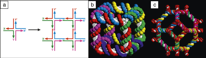
The first notable object to be constructed by DNA nanotechnology methods was a DNA molecule with the connectivity of a stick-cube or a stick-rhombohedron, see Figure 1b. Reference Chen and Seeman2 This is a “zero-dimensional object,” because it is entirely closed and cannot be extended to form a one-dimensional (1D), two-dimensional (2D), or three-dimensional (3D) species. Each vertex corresponds to a three-arm branched junction, and each edge consists of two turns of double helical DNA. The angles between edges are variable, therefore there is no control on the absolute shape. In a sense, this is a topological construction, because the shape is not guaranteed, but the linking and branching are predetermined from the design. Each of the six faces corresponds to a cyclic single strand of DNA (single strand of DNA joined to itself from the beginning to the end, to form a cycle), and each strand is linked twice (because the edges are two turns long) to each of the four faces that flank it. For example, the front face corresponds to the red strand, and it is linked twice to the green strand, the cyan strand, the magenta strand, and the dark blue strands that flank it.
In the hope that a macromolecular version of zeolite A could be synthesized, a truncated octahedron (Figure 1c) was constructed using a solid support methodology. Reference Zhang and Seeman3 The yield of one of the ligations was only 1%, although the rest were nearly 100%. At that time (in the early 1990s), before atomic force microscopy (AFM) was commonly used, the only way to demonstrate the successful synthesis of the target object was by selective cleavage of edges to yield predicted catenanes, linked cyclic objects held together like the links of a chain. It was clear that complex syntheses to produce starting materials were not going to be effective. It was necessary to find a reliable, simple, and robust starting material that could be produced in high yield.
After a certain amount of experimentation, the double crossover (DX) molecule, Reference Fu and Seeman4 an analogue of an intermediate in genetic recombination, was found to have all the desired rigidity properties needed to serve as a starting material for 1D or 2D crystallization. Reference Li, Yang, Qi and Seeman5 This molecule consists of two coplanar double helices joined at least twice. It is stiff, with a persistence length (measure of its stiffness) of approximately 100 nm, Reference Sa-Ardyen, Vologodskii and Seeman6 and there are no floppy angles (angles flank branch points and may be stiff or floppy) that were such a concern with the objects of Figure 1b–c.
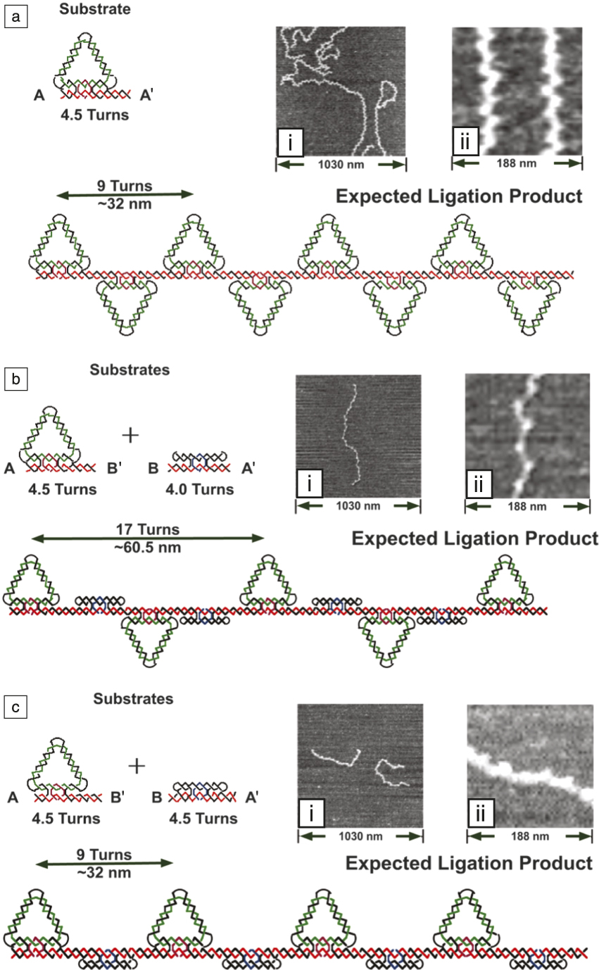
An example of 1D self-assembly Reference Yang, Wenzler, Qi, Li and Seeman7 using the DX molecule is shown in Figure 2a. A triangle with a 4.5-turn DX molecule on its bottom is polymerized into a long molecule and then examined by AFM. The top schematic shows that the triangle should switch orientations with each addition. This is seen in the AFM images on the right. To confirm that the image is not an artifact, a second 1D self-assembly was performed by inserting a 4-turn DX molecule between the triangles, nearly doubling the triangle periodicity (Figure 2b). At the bottom (Figure 2c), a 4.5-turn DX insert returns the spacing to the original spacing, but now all the triangles are pointing the same way, as seen in the AFM images.
Ligation of DNA triangles containing a double crossover (DX) domain. Reference Yang, Wenzler, Qi, Li and Seeman7 (a) (Top) Only the triangle is ligated. Sticky end A and its complement A′ are separated by 4.5 turns, leading to (bottom) a zigzag pattern. At right, (i) a zigzag molecule is visible, and (ii) the higher magnification image reveals that the points of the triangles are separated by the expected nine-turn separation of ∼32 nm. (b) (Top) A triangle and DX molecules are ligated in an alternating pattern. The DX adds four turns to the separation, maintaining (bottom) the zigzag pattern, but almost doubling the separation. At right, (ii) the higher magnification image reveals that the separation of points is nearly double. (c) (Top) The triangle and a 4.5-turn DX are ligated in an alternating pattern. The extra half-turn in the DX now (bottom) eliminates the zigzag pattern and puts all the triangles on the same side of the continuous shaft. This is visible on the right, where the original separation is seen in the atomic force microscope image, but one side is smooth.

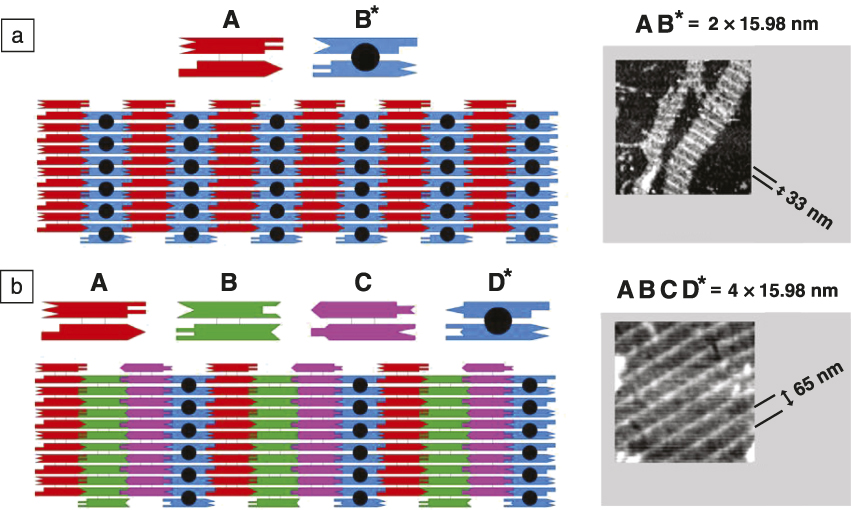
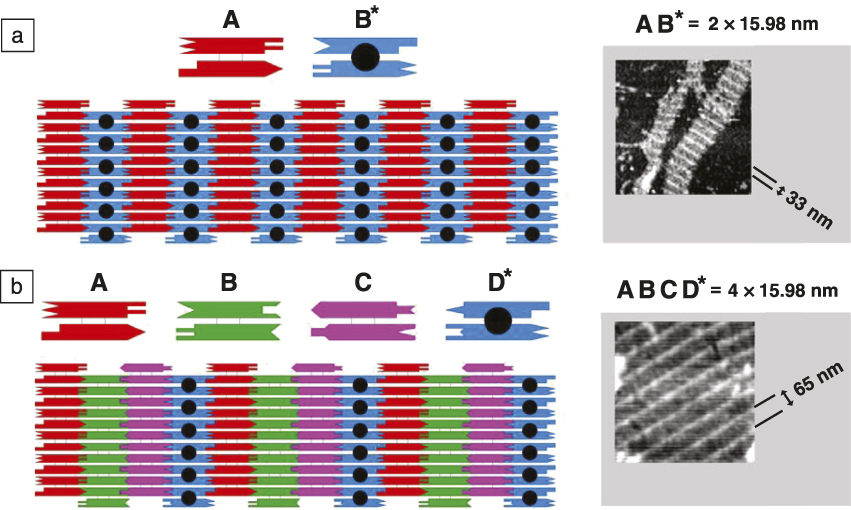
The use of the DX molecule as the repeat component of a 2D lattice has been extremely successful. Reference Winfree, Liu, Wenzler and Seeman8 An example is shown in Figure 3 . The analysis of 2D lattices has been greatly facilitated by the combination of the DX molecule with DX + J molecules, molecules containing one or two hairpin double helices covalently attached and perpendicular to the plane of the DX helix axes. These features lead to stripes in the 2D crystalline pattern, readily visible in the AFM image. The systematic variation of the number of DX and DX + J leads to stripes with predictable separations. Figure 3a shows a schematic in which 16-nm-wide DX and DX + J molecules alternate in a 2D pattern, leading to a stripe that repeats approximately every 32 nm in the AFM micrograph. Figure 3b shows a schematic of four 16-nm-wide DX molecules, in which a DX + J occurs every fourth molecule, such that the AFM pattern shows a stripe that repeats every 64 nm. Numerous other 2D systems have been constructed with small tiles. Reference LaBean, Yan, Kopatsch, Liu, Winfree, Reif and Seeman9,Reference Mao, Sun and Seeman10
Two-dimensional (2D)-DNA arrays. Reference Winfree, Liu, Wenzler and Seeman8 (a) Two double crossover (DX) molecules tile the plane. (Left) A conventional DX molecule, A, and a DX + J molecule, B*, tile the plane. The extra domain (black sphere) on B* leads to stripes. The molecules are 4 × 16 nm, so the stripes are ∼32 nm apart, as seen in (right) the atomic force microscope image. (b) Four DX molecules tile the plane. This arrangement is similar to (a), but there is only one DX + J molecule, D*, so the stripes are separated by ∼64 nm, as seen on the right (AFM image).
DNA-guided nanoparticle 3D assembly
Inspired by the programmability of DNA interactions, the idea of using DNA to guide assembly of nanoparticles was proposed about two decades ago. Reference Alivisatos, Johnsson, Peng, Wilson, Loweth, Bruchez and Schultz11,Reference Mirkin, Letsinger, Mucic and Storhoff12 In comparison to the DNA constructs previously discussed, a nanoparticle, with one of many single- or double-stranded DNA attached to its surface, looks relatively simple. Nevertheless, it turns out to be notoriously difficult to reveal system design requirements and conditions required for 3D crystallization of such systems. We discuss a number of efforts developed in the field for transferring the programmability of interparticle bonds to structural control of 3D nanoparticle lattices.
The major problem encountered in the early days of DNA-nanoparticle crystallization experiments is that complementary DNA-functionalized nanoparticles when hybridizing typically form a 3D disordered aggregate. It was realized that obtaining a crystalline lattice from DNA-grafted nanoparticles is difficult due to the complex interplay of interactions and entropic effects, in addition to the kinetic traps, because of multiple hybridizations between particles. Experimentally, two major schemes were explored for particle assembly, direct hybridization (DH) and linker-mediated hybridization (LH). If complementary DNA strands are grafted onto surfaces of the two respective particles, particles can bind via DH. For LH, strands on particles are not complementary, but specific linkers are required for interparticle hybridization.
For both cases, the interparticle connection rules and distances can be programmed through the choice of DNA motif. Moreover, more than one DNA sequence type can be placed on a particle to provide different addressability (or so-called “colors”) of interactions. Due to the relatively high binding energy of nanoparticles interacting via particle-grafted DNA (∼1–2 kT per base pair), hybridizations of multiple strands among particles, chain entropy and entanglement effects, and particle interactions that charge DNA chains, kinetically arrested disordered states are common. Together with the many-body character of DNA-mediated nanoparticle interactions and their intricate distance and environmental dependence, only amorphous 3D assembly was observed for a long time.
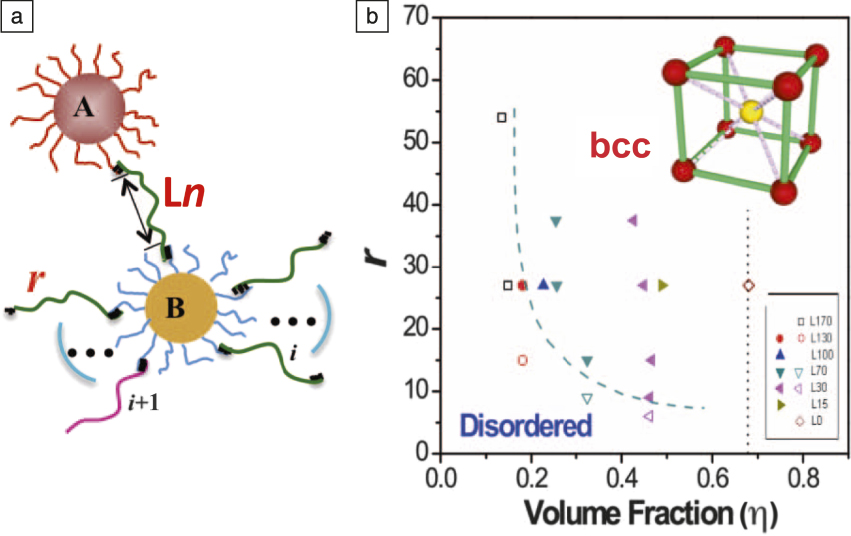
In 2008, Gang’s Reference Nykypanchuk, Maye, van der Lelie and Gang13,Reference Xiong, van der Lelie and Gang14 and Mirkin’s Reference Park, Lytton-Jean, Lee, Weigand, Schatz and Mirkin15 groups were able to demonstrate DNA-driven gold nanoparticle crystallization by adjusting the design of the particle’s DNA shell and the thermal-annealing procedure used. It was also shown theoretically that ordered structures can form appropriate interparticle interaction potentials. Reference Tkachenko16 Through systematic study of the relationship between DNA shell design and phase behavior, two important parameters, DNA linker length and number of linkers per particle ( Figure 4 ), were examined. Reference Xiong, van der Lelie and Gang14,Reference Xiong, van der Lelie and Gang17 Formation of crystalline body-centered-cubic (bcc) nanoparticle lattice occurs for a range of linker lengths, and a minimal number of linkers per particle is required for crystallization. In addition, the order–disorder transition shifts to a higher number of linkers for longer lengths, since an increased entropic elasticity of single-stranded chains can be compensated by a larger number of linker hybridizations. The annealing pathway should allow for de- and re-hybridization between particles in order to achieve an equilibrium state, and this is crucial for establishing crystalline order for those systems whose designs satisfy the appropriate interaction potentials.
Phase diagram of 3D linker-mediated assembly of nanoparticles grafted with DNA. Reference Xiong, van der Lelie and Gang17 (a) The assembly of two types of gold nanoparticles (A and B, grafted with different types of single-stranded DNA) is promoted by a single-stranded DNA linker Ln (n is the number of bases not participating in the hybridization), whose ends are complementary to the strands on A and B. For a range of DNA lengths, (b) (inset) the crystalline body-centered-cubic (bcc) lattice is formed, as confirmed by small-angle x-ray scattering. (b) The phase diagram of the assembled state was studied as a function of the number of DNA linkers (r) and their lengths (n from 0 to 170), which relate to the volume fraction of particles in the lattice and the boundary between disordered and ordered phases was determined (dashed blue line). Reprinted with permission from Reference Reference Xiong, van der Lelie and Gang17. © 2009 American Physical Society. Note: i, index for a DNA out of a total of r DNA on a particle.

Beyond the face-centered cubic (fcc) and bcc phases, the phase diagram can be diversified even for nanoparticles isotopically functionalized with DNA using binary mixtures of nanoparticles of different sizes, where either inorganic nanoparticle core or DNA shell can be used for changing the particle diameter through increasing the nanoparticle size or the number of bases for grafted DNA chains in a shell. Reference Macfarlane, Jones, Senesi, Young, Lee, Wu and Mirkin18 The extended phase diagram of binary spherical DNA-coated nanoparticles, considering stoichiometric mixtures, was also determined. Reference Srinivasan, Vo, Zhang, Gang, Kumar and Venkatasubramanian19,Reference Vo, Venkatasubramanian, Kumar, Srinivasan, Pal, Zhang and Gang20 It is important to stress that use of in situ small-angle x-ray scattering for probing the 3D aggregates under relevant environmental conditions was crucial for revealing crystallization pathways and system design requirements.
The DNA-based approaches developed for gold nanoparticles can be extended to nanoparticles of other materials, when DNA can be attached to the particle surface. Moreover, lattices containing different particles from different materials can be generated, and DNA plays an integral role in uniformly mixing particle types. Several approaches were recently demonstrated for creating such lattices, for instance, bcc superlattices were assembled from amino-DNA functionalized quantum dot and thiolated-DNA covered gold particles. Reference Sun and Gang21 Both carboxylic-based conjugation Reference Sun and Gang21,Reference Zhang, Lu, Yager, van der Lelie and Gang22 and covalent attachment with click-chemistry Reference Zhang, Macfarlane, Young, Choi, Hao, Auyeung, Liu, Zhou and Mirkin23–Reference Heuer-Jungemann, Kirkwood, El-Sagheer, Brown and Kanaras25 methods were used for grafting DNA to nanoparticles. Accordingly, heterogeneous superlattices from functional nanoparticles, including plasmonic, magnetic, catalytic, and luminescent, were formed. In addition to positional order, compositional order (i.e., placement of particles in a unit cell according to their DNA encoding) was also examined for such lattices. It was found that larger single-stranded DNA shells lead to compositional disorder, and the number of DNA strands in a shell affect crystallization. Reference Zhang, Lu, Yager, van der Lelie and Gang22
Three-dimensional self-assembled crystals
Three-dimensional self-assembly of purely DNA systems is different from DNA-functionalized nanoparticles; the criteria for clear observations are typically much stricter for molecular systems versus nanoparticle structures or 2D crystals, due to the much smaller unit cell of DNA crystals and the existing criteria for crystal structures. The atomic force microscope has a typical resolution of 70–100 Å under normal conditions. This resolution is certainly sufficient to differentiate, for instance, the species shown in Figure 3. However, in three dimensions, it is necessary to achieve resolutions better than 10 Å (and preferably better than 5 Å) to observe the product by the only means available, x-ray crystallography. This requires robust motifs that can self-assemble without much floppiness.
To date, there is only one motif that has been designed successfully to provide crystals that diffract x-rays adequately. This is the “tensegrity triangle,” developed by the Mao group. Reference Liu, Wang, Deng, Walulu and Mao26 This motif contains three double helices whose axes are directed in linearly independent directions. Reference Zheng, Birktoft, Chen, Wang, Sha, Constantinou, Ginell, Mao and Seeman27 It has been scaled to contain two turns, three turns, or four turns of the DNA double helix, and it is the basis of almost all 3D crystalline DNA self-assemblies. A second motif, the Paukstelis motif Reference Paukstelis, Nowakowski, Birktoft and Seeman28 was discovered accidentally, and it also can be scaled somewhat to differently sized units. Other DNA motifs have been reported, Reference Simmons, Zhang, Birktoft, Qi, Han, Liu, Sha, Abdallah, Hernandez, Ohayon, Seeman and Yan29 but they do not represent crystals that assume the structures for which they have been designed. From these different crystals, researchers have learned the crystals contain both DNA and solvent. The more of the crystal that is DNA, the better the resolution.
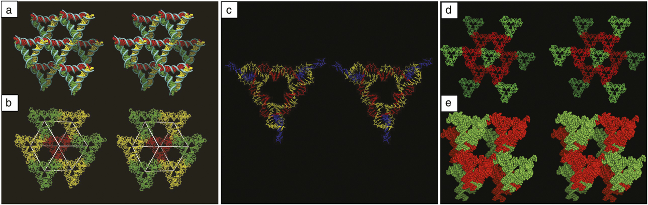
Figure 5a illustrates two different views of a two-turn tensegrity triangle crystal. It shows a tensegrity triangle and its six nearest neighbors, with each of their helix axes differently colored. It is clear that the red helices proceed infinitely in one direction, the green helices in a second direction, and the yellow helices in yet a third direction. They are all held together by sticky ends. Thus, the tensegrity triangles can self-assemble to fill three-space and form a repeating pattern. It is simple to self-assemble rhombohedral crystals that are visible to the naked eye, hundreds of micrometers in a linear dimension. Figure 5b illustrates seven triangles selected differently from those in Figure 5a. These flank a rhombohedral cavity within the crystal, shown in white. The red triangle flanks the rear vertex of the rhombohedron; it is connected to the three yellow triangles that flank vertices somewhat closer to the viewer. The yellow triangles are connected to the green vertices that are closer yet to the viewer. An eighth triangle, not shown for clarity, flanks the front vertex. The central cavity has a volume of ∼200 nm3. The cavity volume for the three-turn triangle lattice is ∼800 nm3 and for the four-turn it is ∼2000 nm3. The crystal structure of a three-turn triangle is shown in Figure 5c; the helical strands are yellow, the cyclic central strand is red, and the crossover strands at the periphery are blue. Reference Nguyen, Birktoft, Sha, Wang, Zheng, Constantinou, Ginell, Chen, Mao and Seeman30
Stereoscopic images of the two-turn tensegrity triangle crystal structure. (a) Each triangle is joined to six other triangles by sticky-ended cohesion. Reference Zheng, Birktoft, Chen, Wang, Sha, Constantinou, Ginell, Mao and Seeman27 The schematic shows that the three directions defined by the helix axes span three-space. The red, green, and yellow directions go from rear to front. (b) Eight triangles surround the vertices of a rhombohedron. The red triangle sits on the rear vertex of a rhombohedron. It is connected to the three yellow triangles that flank vertices nearer to the viewer. The yellow triangles are connected to the green triangles that flank vertices nearer yet to the viewer. The front vertex has been left vacant for clarity, but would contain another red triangle. (c) Stereoscopic image of the three-turn tensegrity triangle. Reference Nguyen, Birktoft, Sha, Wang, Zheng, Constantinou, Ginell, Chen, Mao and Seeman30 The helical strands are shown in yellow, the central nicked cyclic strand is shown in red, and the crossover strands at the periphery are shown in blue. (d) A crystal programmed to contain two molecules per asymmetric unit. Reference Wang, Sha, Birktoft, Zheng, Mao and Seeman31 Both panels are stereographic images of the crystal structure. The green triangle in the center is connected to six red triangles. The next nearest neighbors in the same direction (only) are shown in green. (e) The rhombohedron formed by four molecules of each kind. Eight molecules are shown. The opposite vertices along each edge contain different species of triangles.
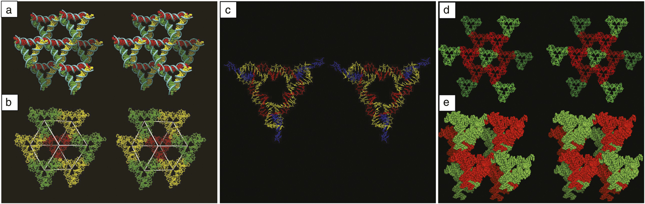
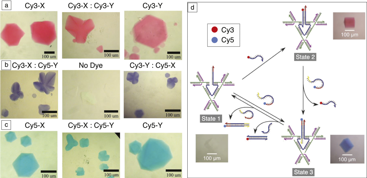
One advantage of using sticky ends to self-assemble crystals is that they enable the choice of the number of molecules in the crystallographic repeat. Reference Wang, Sha, Birktoft, Zheng, Mao and Seeman31 Figure 5d shows a crystal designed to contain two molecules per asymmetric unit, a green molecule (Figure 5d) and a red molecule (Figure 5e). Figure 5d shows a molecular stick diagram, and Figure 5e shows the same system in a space-filling model. The two different molecules can be designed to have different chemistries. For example, Figure 6a illustrates crystals in which the X molecule (left), the Y molecule (right), or both (center) have a pink dye (Cy3) attached to them, and all three sets of crystals are pink. Figure 6c shows the same order of crystals to which a blue dye (Cy5) has been attached, leading to blue crystals. In Figure 6b, the left image has Cy3 attached to the X molecule and Cy5 attached to the Y molecule; in the right image, the order of attachment is reversed. In both cases, the crystals are purple.
Controlling the color—A macroscopic property of a crystal is programmed via the independent addition of two different dye molecules, Cy3 (pink) and Cy5 (blue). Reference Wang, Sha, Birktoft, Zheng, Mao and Seeman31 (a) The X-molecule (left), the Y-molecule (right) or both (center) have Cy3 attached; the crystals are consequently colored pink. (b) The left image has Cy3 attached to the X molecule and Cy5 attached to the Y molecule, whereas the order has been reversed on the right; the crystals are colored purple, as expected. The central image contains control crystals to which no dye was attached. (c) The X-molecule (left), the Y-molecule (right) or both (center) have Cy3 attached; the crystals are now colored blue. (d) Operation of a 3D three-state color device. Reference Hao, Kristiansen, Sha, Birktoft, Hernandez, Mao and Seeman32 The three states (1, 2, and 3) are labeled in gray, and the corresponding crystal images are shown next to the states. The Cy3 and Cy5 fluorescent dyes are covalently attached to the set strands, as indicated by the red and blue dots, respectively. The single strand extending from the triangle in State 1 is complementary to sections of the strands that contain Cy3 or Cy5; the remaining sections act as “toeholds.” The addition of the Cy3-containing strand leads to State 2, leaving the displaced Cy3-containing strand in the mother liquor. Addition of the Cy5-containing strand (able to exploit the red toehold) leads to State 3. The same crystal is shown for each state.
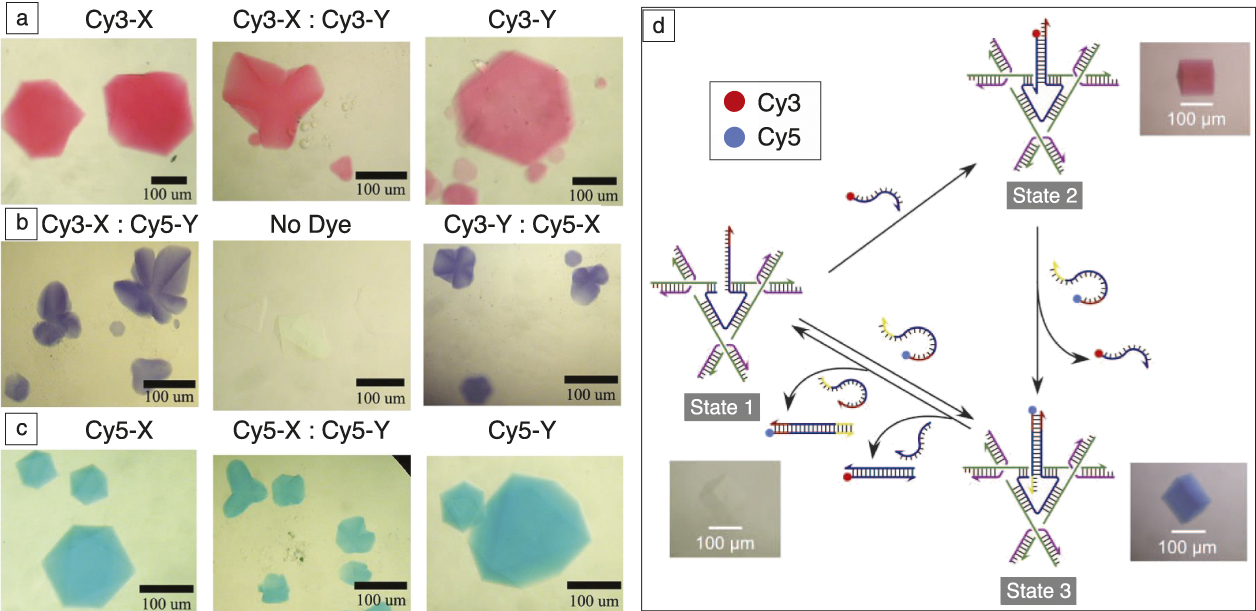
It is beyond the scope of this article to discuss nanomechanical devices in detail. Nevertheless, it is worth mentioning that most interesting devices can be controlled in a sequence-dependent fashion. But can this be done in 3D? Figure 6d illustrates a three-step cycle involving a crystal that can be dyed in a dynamic fashion with the addition of a dye-bearing strand. Reference Hao, Kristiansen, Sha, Birktoft, Hernandez, Mao and Seeman32 State 1 (lower left corner) shows a colorless crystal in which the central strand of a tensegrity triangle has been elongated. A strand bearing the Cy3 dye is added in the transition to State 2 (upper right) of the crystal. The crystal is seen to change from colorless to red. In the transition from State 2 to State 3 (lower right), the Cy3 strand is removed, and a Cy5 strand replaces it, turning the crystal blue. This system can be cycled numerous times.
In recent work, nanoparticles, semiconductors, Reference Wang, Sha, Kristiansen, Hernandez, Hao, Mao, Canary and Seeman33 and triplex-forming oligonucleotide Reference Rusling, Chandrasekaran, Ohayon, Brown, Fox, Sha, Mao and Seeman34 strands have been added to tensegrity triangle crystals. In this issue, the theme articles describe DNA origami to be a great platform for the attachment of specific molecular species, particularly to planar and tubular structures, as well as for 3D particle crystals. However, it is important to remember that 3D crystalline arrays are also amenable to the placement of molecular species, and these can be characterized by x-ray crystallography. A wide variety of specific 3D targets can be produced readily using the self-assembly methods of DNA nanotechnology.
Toward designed nanoparticle lattices
Although the DNA shell of nanoparticles can be considerably tailored through sequence design and the composition and length of the strands, it is difficult to diversify the symmetry of the formed lattices this way. It is even more challenging to realize designed lattices where the objective is to organize the same nanoparticles into prescribed lattice types. Establishing approaches for the creation of designed nanoparticle lattices is invaluable for nanomaterial applications, from metamaterial to mechanics and magnetic materials to membranes, which is a strong motivator for continued effort. The key point for achieving this level of structural control is to combine bond directionality and DNA addressability provided by its sequence encoded interactions. In this respect, we discuss several recently developed approaches.
Extremely rich phase behavior was shown computationally for solid polyhedra due to the interplay of entropic and packing effects. Reference Jones, Macfarlane, Lee, Zhang, Young, Senesi and Mirkin35 For shaped DNA-functionalized nanoparticles, enthalpic and polymeric contributions can result in substantial modification of the predicted phases. DNA-guided assembly of shaped nanoparticles drives systems to the phases in which hybridization between complementary chains is maximized. Reference Jones, Macfarlane, Lee, Zhang, Young, Senesi and Mirkin35 For example, rods form hexagonally packed layers, and prisms form linear arrays. The details of the DNA design are critical for the formed phases—for rigid DNA motifs, the phases might resemble those observed for attractive solid objects since rigid motifs do not contribute significantly to repulsion, but for single-stranded motifs, due to their polymeric nature, unusual assembly behavior is observed. Reference Vial, Nykypanchuk, Yager, Tkachenko and Gang36 For instance, spontaneous symmetry breaking and consequent formation of linear arrays occurs for radially isotropic rods or mixtures of rods and spheres. Reference Vial, Nykypanchuk, Yager, Tkachenko and Gang36
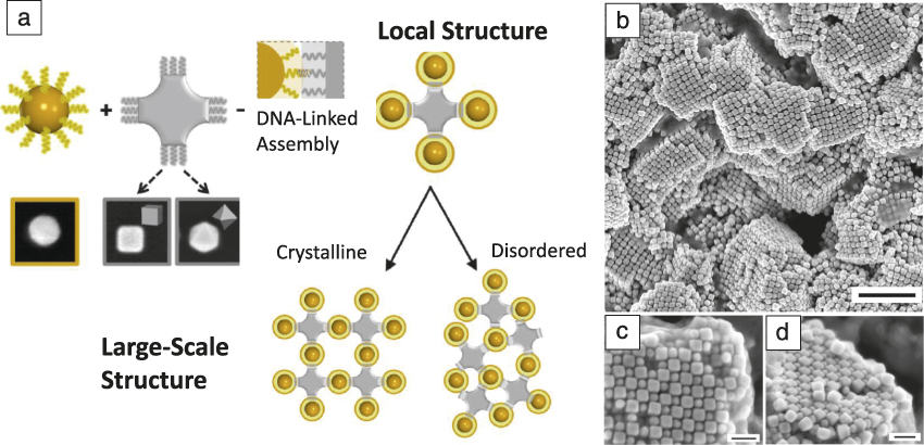
The directionality of interactions imposed by the shaped nanoparticles can be used to coordinate isotropic spherical particles in lattices, which typically do not occur for spheres. For example, cubes and octahedra will coordinate spheres into sixfold or eightfold symmetry, respectively, due to their shape and DNA-hybridization between DNA attached correspondingly to shaped and spherical nanoparticles. Reference Lu, Yager, Zhang, Xin and Gang37 For the appropriate choice of particle sizes and DNA motifs, this local coordination is translated into lattices ( Figure 7 ), which are not native for spheres, but rather, dictated by the shapes of nanoparticles. For instance, simple cubic arrangement was observed Reference Srinivasan, Vo, Zhang, Gang, Kumar and Venkatasubramanian19 for the mixture of complementary functionalized cubes and spheres. However, the crystallization in such systems might be more intricate since (1) particles have to be properly oriented, and thus annealing is more complex for finding both particle position and orientation in a lattice in comparison to systems of spherical particle where only the position is important; (2) differently shaped particles provide substrates of different curvature for grafted DNA that produce a heterogeneous environment for chains between particles; and (3) relative particle sizes affect bond directionality.
Formation of lattices through directional bonds of shaped and spherical DNA-encoded nanoparticles. Reference Lu, Yager, Zhang, Xin and Gang37 (a) Spherical nanoparticles (yellow) are isotropic nano-objects and are coordinated by anisotropic nanoparticles (gray) that have a low-order symmetry. The interactions between isotropic and anisotropic particles are regulated by complementary DNA strands. The directional bonding of anisotropic particles coordinates sphere clusters with a particular local symmetry. The local coordination can be translated into the formation of large-scale 3D assemblies with either disordered or ordered phases, depending on the DNA shell design and particle sizes. For the electron microcope images, the inner frame of images is 100 nm). (b) Large-scale view of the formed lattice as imaged by scanning electron microcopy; scale bar is 500 nm. (c) and (d) Top and side views, respectively, of the crystalline domains; scale bars are 100 nm.

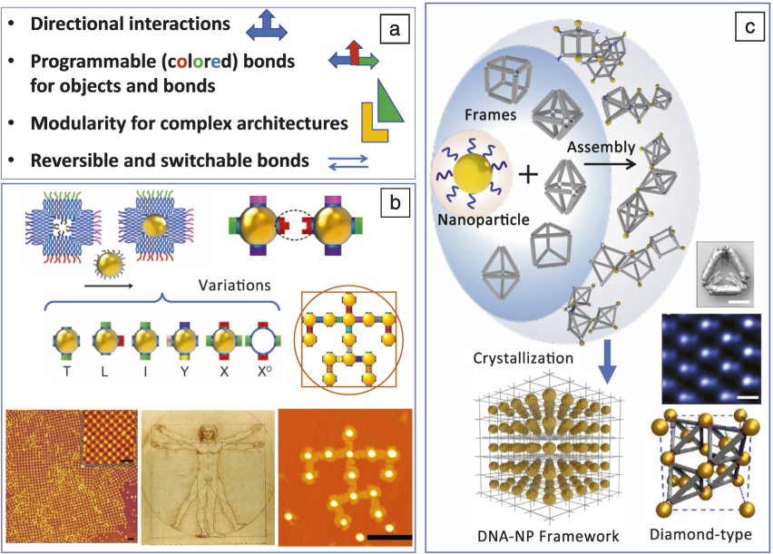
To further extend this idea of combining DNA-programmable bonds and geometrical constraint for nanoparticle assembly, shaped DNA constructs can be used as a building block in assembly of nanoparticle-based 2D and 3D lattices. Figure 8a summarized exciting features of systems of nanoparticles combined with well-defined DNA constructs. The integration creates a highly versatile and functional nanoscale systems—tailorable interactions are provided by DNA, and functions are determined by the nanoparticles—that promise new perspectives for materials scientists for building 3D architectures in a designed manner. For example, nanoparticles can be connected in clusters or low-dimensional arrays using 3D origami polyhedral frames. Reference Tian, Wang, Liu, Xin, Li, Ke, Shih and Gang38 The proposed DNA-nanoparticle framework assembly strategy Reference Liu, Tagawa, Xin, Wang, Emamy, Li, Yager, Starr, Tkachenko and Gang39,Reference Tian, Zhang, Wang, Xin, Li and Gang40 relies on the ability to control the symmetry of the nanoparticles lattices through the introduction of specific shapes of polyhedra DNA frames that link particles (Figure 8c). The frames can be designed using the 3D DNA origami approach. Reference Douglas, Dietz, Liedl, Hogberg, Graf and Shih41 In this assembly strategy, particles hybridize to vertices of DNA frames, but the topology of interparticle connections and, ultimately, the lattice symmetry depends on the particular frame shape. Reference Tian, Zhang, Wang, Xin, Li and Gang40 The crystallization of DNA-nanoparticle frameworks was observed for particular frame shapes (cube, octahedra, prism, elongated octahedra), while using some polyhedra did not result in a crystalline structure, possibly due to the complex and not yet understood interplay of enthalpic and entropic effects. Also, there are certain requirements for DNA motifs that link particle to origami for the formation of crystalline phases. Crystallization occurs for single-stranded linkages of moderate lengths. Reference Tian, Zhang, Wang, Xin, Li and Gang40 Overall, this strategy paves the road for the assembly of designed lattices via engineered frame geometries and location of DNA-encoded spots for particle attachment.
(a) The integration of nanoparticles with DNA constructs for assembly of designed lattices and architectures. Major design parameters for controlling the assembly of DNA-driven nanoparticle systems. (b) Arbitrary architectures from polychromatic modules integrate planar DNA frame and nanoparticles. Reference Liu, Halverson, Tian, Tkachenko and Gang44 Each module possesses both directional and “colored” interactions (different topological types are shown: T, L, I, Y, X, XO). This allows for the assembly of different types of modules into diverse architectures such as (bottom left) a periodic lattice, (bottom middle) Leonardo da Vinci’s Vitruvian Man figure, and (bottom right) as imaged by AFM. (c) The strategy for the assembly of 3D nanoparticle lattices using DNA origami 3D frames. Reference Tian, Zhang, Wang, Xin, Li and Gang40 (Top) Nanoparticles assembled in ordered 3D DNA-NP frameworks by origami polyhedra of different shapes that provide a local particle coordination, consequently leading to (bottom left) the formation of different lattice symmetries. (Bottom right) Diamond-type lattice from gold nanoparticles is obtained when (middle right) a tetrahedral DNA frame (scale bar is 20 nm) is used to connect particles at vertices, and a particle is also inserted inside a tetrahedral frame. Reference Liu, Tagawa, Xin, Wang, Emamy, Li, Yager, Starr, Tkachenko and Gang39 (Top right) TEM image visualizes the 110 plane of the diamond lattice of gold particles; scale bar is 50 nm.

The next level of lattice engineering can be achieved by integrating particles and the DNA frame; Reference Licata and Tkachenko42,Reference Li, Liu, Yu, Jiang and Mao43 in this case, DNA-coated nanoparticles are hybridized with DNA strands inside a DNA frame. This provides particles with anisotropic interactions defined by the cage geometry, while the frames are connected by particles as described previously. Such an approach was realized for solving the long-standing challenge in colloidal science, the assembly of diamond-type lattices from nanoparticles. Reference Liu, Tagawa, Xin, Wang, Emamy, Li, Yager, Starr, Tkachenko and Gang39 In this case, isotropic spherical nanoparticles and nanoparticles encaged by a tetrahedral origami frame formed a particle diamond lattice due to the peculiar binding between truncated tetrahedral vertices and particles and the resulting arrangements of tetrahedra bonds at vertices. Reference Diao, Zhou, Kurosawa, Shaw, Wang, Park, Guo, Reinspach, Gu, Gu, Tee, Pang, Yan, Zhao, Toney, Mannsfeld and Bao24,Reference Heuer-Jungemann, Kirkwood, El-Sagheer, Brown and Kanaras25
To meet the challenges of building nanoscale periodic arrays with an even greater degree of complexity, including quasiperiodic lattices, multiscale organization, and control over the orientation of particles, the addressability (“color”) can be used for hybridization differentiation. Recently, an idea (Figure 8b) was explored for the formation of planar arbitrarily designed clusters and lattices through the use of origami-nanoparticle modules with different addressable bonds, so-called polychromatic modules. Reference Liu, Halverson, Tian, Tkachenko and Gang44 By mixing various topological types of these modules and by controlling their stoichiometric ratio in the hetero-mixture, the assembly process can be directed toward the desired architectures. Both periodic and arbitrarily prescribed planar nanoparticle assemblies were generated, including non-trivial structures such as a nanoscale version of Leonardo da Vinci’s Vitruvian Man. The approach can be potentially extended to 3D. Such multicolored addressability and directionality might require developing new principles for structure design and assembly in order to minimize the number of building elements and error rates. Reference Liu, Halverson, Tian, Tkachenko and Gang44
Finally, given the plasticity of DNA, reconfigurable particle superlattices can be created using induced changes in DNA that link particles. For example, osmotic pressure, molecular intercalation, Reference Pal, Zhang, Kumar and Gang45 and salt concentration Reference Xiong, Sfeir and Gang46–Reference Srivastava, Nykypanchuk, Fukuto and Gang48 were used to manipulate lattice constants. A specific response (25% interparticle distance change) to reactive strands was shown for nanoparticles linked in a lattice with a switchable DNA “device.” Reference Maye, Kumara, Nykypanchuk, Sherman and Gang49 To go beyond lattice constant manipulation, a novel concept of programmable switching of particle lattice symmetry by reprogramming interparticle bonds was demonstrated. Reference Zhang, Srinivasan, Vo, Pal, Kumar and Gang50,Reference Kim, Macfarlane, Jones and Mirkin51 The approach opens opportunities for creating switchable 3D particle lattices with regulated material performance.
Summary and outlook
Structural DNA nanotechnology began as an idea to rationalize an organization of molecular and nanoscale components in 3D arrays using DNA scaffolds for solving problems in protein crystallography and challenges in nanomaterial fabrication. The strength of DNA-based methods for controlling an organization of matter on small scales in 3D became evident in the last decade, when ordered molecular, nano- and micro-scale systems were demonstrated. With its ability to assemble a broad range of functional components (e.g., fluorophores fluorophores, plasmonic, or light-emitting nanoparticles), DNA entered the materials science arena as a powerful tool for 3D material creation. The common trend of recent years is aspiring to achieve a high level of designer control over the 3D DNA arrays and the components they can organize. In this respect, isolated DNA constructs, such as DNA motifs of various types and DNA origami, can serve as an organization of 3D lattices. In the future, we envision that DNA addressability combined with the diversity of its constructs will allow for the 3D “self-printing” of functional materials by means of DNA-powered self-assembly.
Acknowledgments
N.S. has been supported by the following grants: GM-29554 from NIGMS, Grants EFRI-1332411, and CCF-1526650 from the NSF, Multidisciplinary University Research Initiatives (MURI) W911NF-11–1-0024 from the Army Research Office, MURI N000140911118 from the Office of Naval Research, DE-SC0007991 from the US Department of Energy (DOE) for DNA synthesis and partial salary support, and Grant GBMF3849 from the Gordon and Betty Moore Foundation. O.G. has been supported by the US DOE, Office of Basic Energy Sciences, Grant DE-SC0008772. The research was conducted at the Center for Functional Nanomaterials, which is a US DOE Office of Science Facility, operated at Brookhaven National Laboratory under Contract No. DE-SC0012704.

Nadrian C. Seeman is the Margaret and Herman Sokol Professor of Chemistry at New York University. Following a BS degree in biochemistry from The University of Chicago, he received his PhD degree in biological crystallography from the University of Pittsburgh. His postdoctoral training, at Columbia University and Massachusetts Institute of Technology, emphasized nucleic acid crystallography. Seeman has published more than 300 papers and has won several awards, including the Feynman Prize, the Emerging Technologies Award, the Rozenberg Tulip Award in DNA Computing, the World Technology Network Award in Biotechnology, the ISNSCE Nanoscience Prize, and The Kavli Prize in Nanoscience. He is a Thomson-Reuters Citation laureate, has been elected a Fellow of the AAAS, the Royal Society of Chemistry, and the American Crystallographic Association, and he has been inducted into the American Academy of Arts & Sciences. Seeman can be reached by email at ncs1@nyu.edu.

Oleg Gang is a professor of chemical engineering and applied physics and materials science at Columbia University, and a group leader at the Center for Functional Nanomaterials (CFN) at Brookhaven National Laboratory. He received his PhD degree in physics from Bar-Ilan University, Israel, in 2000, and was a postdoctoral Rothschild Fellow at Harvard University. He joined Brookhaven National Laboratory in 2002 as a Goldhaber Distinguished Fellow. Since 2008, he has led CFN’s Soft and Biological Nanomaterials Group. He joined the Department of Chemical Engineering and the Department of Applied Physics and Applied Mathematics at Columbia University in 2016. His research interests focus on structural and self-assembly properties of soft matter. His awards include the Gordon Battelle Prize for Scientific Discovery and Battelle Inventor of the Year. He is a Fellow of the American Physical Society. Gang can be reached by email at og2226@columbia.edu.