1 Introduction
Ion streaming instability can be excited at arbitrary places in a plasma where there is a relative motion of the ions with respect to the resting plasma system (Miyamoto Reference Miyamoto1980; Chen Reference Chen2016). In the plasma bulk region, the ion streaming instability was predicted in many plasma environments, e.g. magnetized dusty plasmas (Rosenberg & Shukla Reference Rosenberg and Shukla2004; Shukla et al. Reference Shukla, Shukla, Brodin and Stenflo2008), auroral-acceleration-zone plasmas (Muschietti & Roth Reference Muschietti and Roth2008), complex plasmas with non-Maxwellian ions (Kählert Reference Kählert2015; Quest, Rosenberg & Kercher Reference Quest, Rosenberg and Kercher2017), negative ion source plasmas (Barminova & Chikhachev Reference Barminova and Chikhachev2016; Kumar & Mathew Reference Kumar and Mathew2017), electron–positron–ion plasmas (Saleem & Khan Reference Saleem and Khan2005) and ion beam propagation in inertial fusion plasmas (Tokluoglu et al. Reference Tokluoglu, Kaganovich, Carlsson, Hara and Startsev2018). In the plasma presheath region (i.e. the region between bulk plasma and near-wall sheath), the ion–ion two-stream instability enhanced friction was theoretically and numerically (Baalrud, Hegna & Callen Reference Baalrud, Hegna and Callen2009; Baalrud, Callen & Hegna Reference Baalrud, Callen and Hegna2010; Baalrud et al. Reference Baalrud, Lafleur, Fox and Germaschewski2015; Baalrud Reference Baalrud2016) demonstrated to explain many experimental observations (Hershkowitz Reference Hershkowitz2005; Hershkowitz et al. Reference Hershkowitz, Ko, Wang and Hala2005; Wang & Hershkowitz Reference Wang and Hershkowitz2006; Lee, Hershkowitz & Severn Reference Lee, Hershkowitz and Severn2007a ; Lee, Oksuz & Hershkowitz Reference Lee, Oksuz and Hershkowitz2007b ; Oksuz, Lee & Hershkowitz Reference Oksuz, Lee and Hershkowitz2008) that each species of ion entered the sheath edge nearly at the same ‘system’ ion sound velocity, rather than their individual Bohm velocities; while recent experiment showed that the ion–neutral collisions can decay this two-stream instability, and thus the ions enter the sheath edge with their own Bohm velocities (Kim et al. Reference Kim, Song, Roh, Jang, Ryu, Huh and Kim2017).
In fact, these theoretical analyses of the ion streaming instability were based on the dispersion relation in uniform plasmas (Baalrud et al. Reference Baalrud, Hegna and Callen2009, Reference Baalrud, Callen and Hegna2010, Reference Baalrud, Lafleur, Fox and Germaschewski2015; Baalrud Reference Baalrud2016), but in the non-uniform plasma sheath region, the ion streaming instability should be a typical eigenvalue problem due to the sharp parameter variation. In Zhang & Wang (Reference Zhang and Wang2012), the ion–ion two-stream instability in a classic sheath was studied as an eigenvalue problem, and an instability with frequencies well below the ion plasma frequency arose. However, the response of electrons was neglected. This then motivated us to study the ion–electron two-stream instability in existing three sheath structures (i.e. classic, inverse and space-charge limited (SCL) sheaths). The ion–electron two-stream instability has been well studied in uniform plasmas (e.g. Chen Reference Chen2016), while this work focuses on this problem in non-uniform plasma sheaths.
In general, the three sheath structures can be formed near a floating plasma–wall boundary. In the static regime, the charge balance at the wall should be satisfied,
 $$\begin{eqnarray}\displaystyle J_{\text{ion}}=J_{\text{ein}}-J_{\text{ee}}=J_{\text{ein}}(1-\unicode[STIX]{x1D6E4}), & & \displaystyle\end{eqnarray}$$
where,
 $J_{\text{ein}}~({\geqslant}0)$
is the total incident electron flux,
 $J_{\text{ee}}~({\geqslant}0)$
is the total emitted electron flux and
 $\unicode[STIX]{x1D6E4}=J_{\text{ee}}/J_{\text{ein}}$
is the total electron emission coefficient,
 $J_{\text{ion}}~({\geqslant}0)$
is the total ion flux at wall (assuming that the ions are univalent, i.e. single charged). When the wall electron emission is weak or negligible (e.g.
 $\unicode[STIX]{x1D6E4}\ll 1$
), the charge balance at the wall can be maintained, and the plasma sheath presents a classic sheath structure with a monotonically decreasing potential distribution perpendicular to wall (Langmuir Reference Langmuir1928; Tonks & Langmuir Reference Tonks and Langmuir1929; Bohm Reference Bohm, Guthrie and Wakerling1949; Riemann Reference Riemann1991), as shown in figure 1(a). However, when the wall boundary presents strong electron emission (e.g.
 $\unicode[STIX]{x1D6E4}>1$
), the charge balance at wall cannot be satisfied, and thus structure transition of the classic sheath will occur, which widely exists in laboratory and space plasma boundaries, e.g. the photoelectron sheath near the lunar surface (Nitter, Havnes & Melandsø Reference Nitter, Havnes and Melandsø1998), the thermoelectric emissive solid surface (Takamura et al.
Reference Takamura, Ohno, Ye and Kuwabara2004) and emissive probe (Sheehan & Hershkowitz Reference Sheehan and Hershkowitz2011), the Hall thruster (Sydorenko et al.
Reference Sydorenko, Kaganovich, Raitses and Smolyakov2009; Taccogna Reference Taccogna2014) and the fusion reactor (Lee & Krasheninnikov Reference Lee and Krasheninnikov2013; Vaverka et al.
Reference Vaverka, Richterová, Vyšinka, Pavlů, Šafránková and Němeček2014).
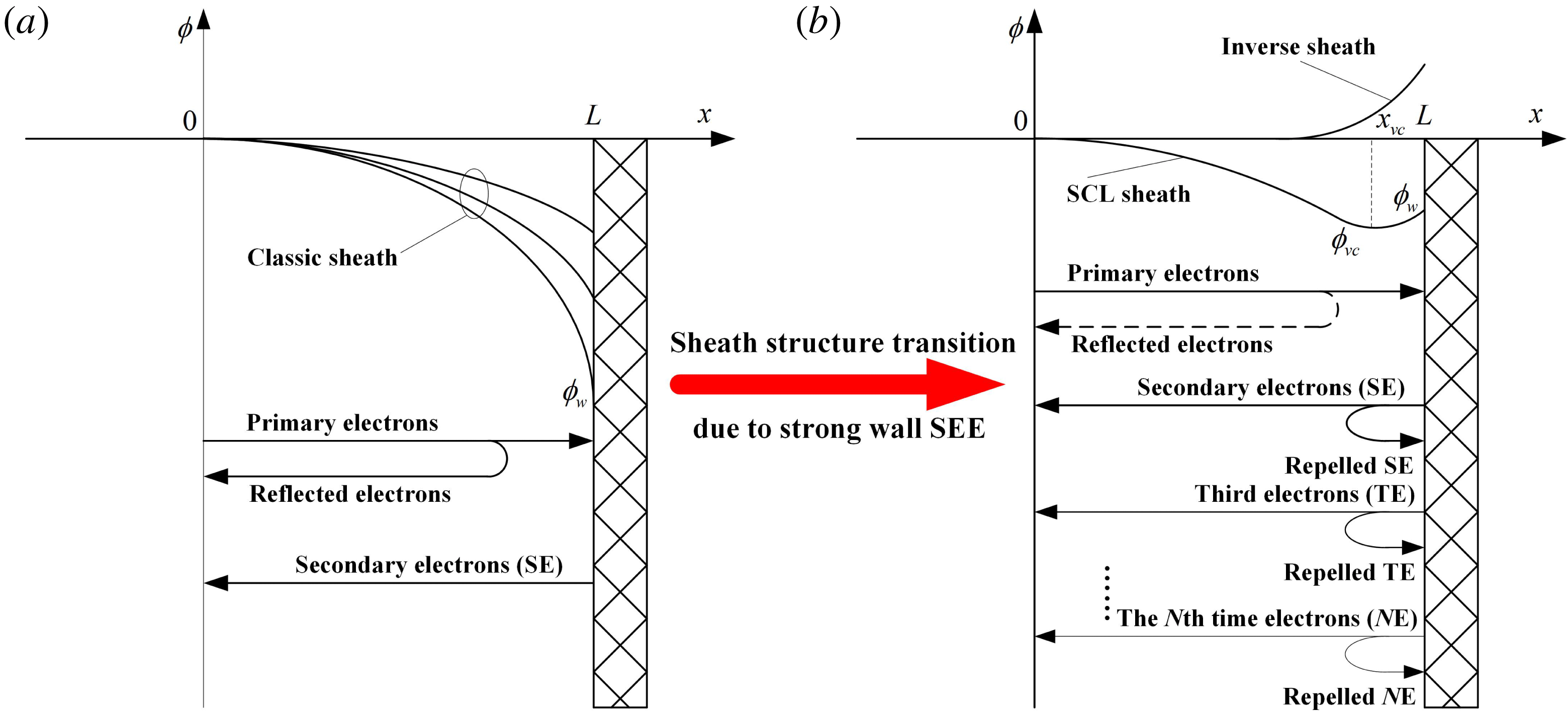
Schematic potential distribution and SEE process in different sheaths near a floating wall: (a) classic sheath configuration with single-step SEE process, and (b) SCL and inverse sheath configurations with multistep SEE process, the dashed line means that the flux of reflected primary electrons only exists in the SCL sheath regime.
 $x=0$
and
 $x=L$
are sheath edge and wall surface respectively,
 $\unicode[STIX]{x1D719}_{w}$
and
 $\unicode[STIX]{x1D719}_{\text{vc}}$
are the electric potentials at the wall and virtual cathode (i.e.
 $x=x_{\text{vc}}$
) respectively.

Figure 1(b) shows two possible transited sheath structures which have a near-wall increasing potential distribution in order to repel emitted electrons back to wall, i.e. increase
 $J_{\text{ein}}$
and thus make
 $\unicode[STIX]{x1D6E4}\leqslant 1$
. Hobbs & Wesson (Reference Hobbs and Wesson1967) first predicted that the wall potential
 $\unicode[STIX]{x1D719}_{w}$
increases with enhancement of the wall electron emission, and the classic sheath will transit into a SCL sheath regime when
 $\unicode[STIX]{x1D6E4}$
exceeds a critical value
 $\unicode[STIX]{x1D6E4}_{c,\text{SCL}}=1-8.3(m_{e}/m_{i})^{0.5}$
, where
 $m_{e}$
and
 $m_{i}$
are the masses of the electron and ion respectively. In their work, the energy of the emitted electrons at the wall was neglected. With a half-Maxwellian distribution assumption for thermionic emission electrons, Sheehan et al. (Reference Sheehan, Hershkowitz, Kaganovich, Wang, Raitses, Barnat, Weatherford and Sydorenko2013, Reference Sheehan, Kaganovich, Wang, Sydorenko, Raitses and Hershkowitz2014) found that the critical SCL sheath has a solution if the temperature ratio of plasma electrons to emitted electrons is no less than unity. Qing & Hu (Reference Qing and Hu2017) found that different assumptions of the total emitted electron velocity distribution (EEVD) can significantly affect the range of average energy ratio of emitted electrons to primary electrons, in which the critical SCL sheath has a solution. This then indicates that the classic sheath may transit to an inverse sheath structure when the ratio is out of the range. In fact, Campanell (Reference Campanell2013) has predicted an entirely inverse sheath structure with no ions through the sheath region by an analytical sheath model, with an assumption that the emitted electrons have a half-Maxwellian distribution. Recently, Qing & Wu (Reference Qing and Wu2018) found that, with the enhancement of electron emission at a floating dielectric wall, the classic sheath will transit to an inverse sheath regime due to the relatively large average energy of emitted secondary electrons, while the classic sheath near a thermionic emitting surface will transit to a SCL sheath regime due to the ‘cold’ emitted electrons. Moreover, it was found that the inverse sheath and SCL sheath can emerge in pairs (Qing & Zhao Reference Qing and Zhao2018), and the SCL sheath will transit to the inverse sheath regime due to the ionization and charge exchange collisions in the sheath region (Campanell & Umansky Reference Campanell and Umansky2016, Reference Campanell and Umansky2017).
In this paper, we are dedicated to distinguishing the ion–electron two-stream instability in different sheaths formed between a Maxwellian plasma source and a dielectric wall with secondary electron emission (SEE). It is found that the sheath structures influence the ion streaming instability dramatically. This paper is organized as follows. In § 2, the background parameter distributions such as electric potential, ion velocity and the densities of ions and electrons in the sheath region are solved based on recent developed 1D3V (one-dimensional space and three-dimensional velocities), static collisionless kinetic sheath model (Qing & Wu Reference Qing and Wu2018; Qing & Zhao Reference Qing and Zhao2018). In § 3, the eigenvalue problem model of the ion–electron two-stream instability in the sheath region is described. In § 4, the numerical results of the eigenvalue equations and ion–electron two-stream instability growth rate or damping in the three sheath regimes are presented and discussed. Conclusions are given in § 5.
2 Steady-state solutions of different sheath structures near a dielectric wall with SEE
In order to reveal the ion streaming instability in the sheath region, we need first to obtain the steady-state parameter distributions, i.e. the background plasma sheath system that a perturbation will propagate in. Considering that the background parameter distributions in the sheath may have a significant influence on the perturbation propagation process, we adopt a well-developed 1D3V kinetic sheath model with a fully self-consistent wall SEE condition to calculate the steady-state parameter distributions in sheath.
2.1 The 1D3V kinetic sheath model with fully self-consistent wall SEE condition
The detailed 1D3V, static, collisionless kinetic sheath model between a Maxwellian plasma source and a dielectric wall with a fully self-consistent SEE condition was proposed in Qing & Wu (Reference Qing and Wu2018) and Qing & Zhao (Reference Qing and Zhao2018). Here we briefly introduce it as follows.
As shown in figure 1(a,b), at the surface of a finite, smooth, floating dielectric wall (i.e. boron nitride (BN) ceramic), the condition of a quasineutral plasma with Maxwellian electrons and pure univalent (i.e. single-charged) cold ions may be satisfied. The sheath forms between the upstream plasma and the dielectric wall surface. The potential
 $\unicode[STIX]{x1D719}(x)$
in the sheath region satisfies Poisson’s equation,
 $$\begin{eqnarray}\displaystyle \frac{\text{d}^{2}\unicode[STIX]{x1D719}}{\text{d}x^{2}}=-\frac{e}{\unicode[STIX]{x1D700}_{0}}(n_{i}-n_{\text{pe}}-n_{\text{ee}}), & & \displaystyle\end{eqnarray}$$
where,
 $\unicode[STIX]{x1D700}_{0}$
is the permittivity of free space,
 $n_{i}$
is the ion density,
 $n_{\text{pe}}$
is the density of electrons arriving from the upstream plasma,
 $n_{\text{ee}}$
is the density of electrons arriving from surface emission and
 $n_{\text{pe}}+n_{\text{ee}}=n_{e}$
is the total electron density.
The electric potentials at
 $x=0$
and
 $x=L$
are set as
 $\unicode[STIX]{x1D719}(0)=0$
,
 $\unicode[STIX]{x1D719}(L)=\unicode[STIX]{x1D719}_{w}$
respectively. At the dielectric wall surface (i.e.
 $x=L$
), the current balance condition of (1.1) should be satisfied. And at the sheath edge (i.e.
 $x=0$
), the quasineutral condition and the Bohm criterion should be satisfied respectively,
 $$\begin{eqnarray}\displaystyle & \displaystyle n_{i}(0)=n_{0}=n_{\text{pe}}(0)+n_{\text{ee}}(0), & \displaystyle\end{eqnarray}$$
 $$\begin{eqnarray}\displaystyle & \displaystyle \lim _{x\rightarrow 0^{+}}\left[\left(\frac{\text{d}n_{i}}{\text{d}\unicode[STIX]{x1D719}}-\frac{\text{d}n_{\text{pe}}}{\text{d}\unicode[STIX]{x1D719}}-\frac{\text{d}n_{\text{ee}}}{\text{d}\unicode[STIX]{x1D719}}\right)\unicode[STIX]{x1D719}\right]\geqslant 0. & \displaystyle\end{eqnarray}$$
The univalent ions are assumed to be cold with an energy
 $E=m_{i}v_{i0}^{2}/2$
at the sheath edge, where
 $v_{i0}$
is the ion velocity. The source electrons at the plasma region are assumed to have an isotropic Maxwellian distribution with temperature
 $T_{e}$
, in units of eV. Therefore, the primary electrons at the sheath edge with velocity
 $V_{x}\geqslant 0$
approximately obey a half-Maxwellian distribution in the
 $x$
direction,
 $$\begin{eqnarray}\displaystyle f_{\text{pe}}(x=0,V_{x})=n_{e0}\left(\frac{m_{e}}{2\unicode[STIX]{x03C0}T_{e}}\right)^{1/2}\exp \left(-\frac{m_{e}V_{x}^{2}}{2T_{e}}\right),\quad V_{x}\geqslant 0. & & \displaystyle\end{eqnarray}$$
It needs to be noted that, under the classic sheath and SCL sheath regimes, the primary electrons at the sheath edge obey a cutoff Maxwellian distribution due to the repelling of plasma electrons in the sheath region by the potential barrier; however, under the inverse sheath regime, the plasma electrons are accelerated to the wall with no reflected primary electrons, as shown in figure 1(b).
Then, for a given sheath structure in figure 1, the primary electron velocity distribution
 $f_{\text{pe}}(x=L,V_{x})$
at the wall and the corresponding normalized flux probability density
 $\overset{\frown }{F}_{\!\text{pe}}(L,V_{x})$
can be expressed. And, based on the detailed SEE probabilistic model of the BN ceramic and the corresponding Monte Carlo simulation method described in Qing & Wu (Reference Qing and Wu2018), the fully self-consistent normalized total EEVD
 $\overset{\frown }{f}_{\!\text{ee}}(x=L,V_{x}<0)$
and total SEE coefficient
 $\unicode[STIX]{x1D6E4}$
can be obtained. It is worth noting that the multistep electron emission (MEE) phenomenon due to the near-wall potential increment of the inverse sheath and SCL sheath is also considered self-consistently. The detailed parameters of
 $\overset{\frown }{f}_{\!\text{ee}}(x=L,V_{x}<0)$
and
 $\unicode[STIX]{x1D6E4}$
for a wide range of
 $T_{e}$
were listed in Qing & Wu (Reference Qing and Wu2018) and Qing & Zhao (Reference Qing and Zhao2018), and the detailed control equations for the three sheaths were described.
Below, we present the solved steady-state parameter distributions such as electric potential
 $\unicode[STIX]{x1D719}$
, electron density
 $n_{e}$
and ion density
 $n_{i}$
and velocity
 $v_{i}$
in the three sheath regions respectively, within a wide range of
 $T_{e}$
. Here we set
 $L=100\unicode[STIX]{x1D706}_{\text{D}}$
which is enough to include the sheath region and partial presheath region, where
 $\unicode[STIX]{x1D706}_{\text{D}}=\sqrt{T_{e}\unicode[STIX]{x1D700}_{0}/n_{0}e^{2}}$
is the Debye length and
 $e$
is the unit charge.
2.2 Steady-state parameter distributions in a classic sheath
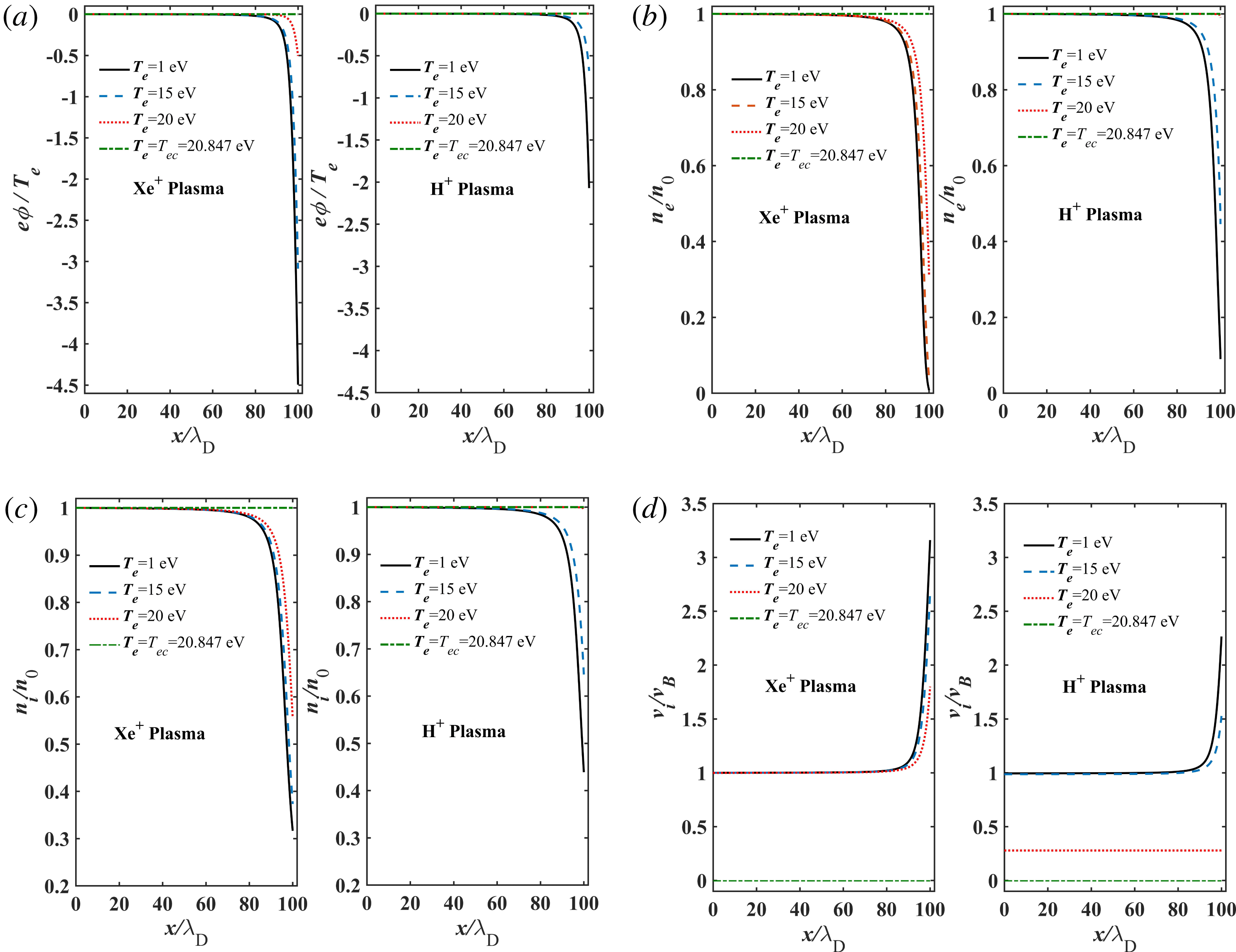
Figure 2 shows the solved parameter distributions in a classic sheath when
 $T_{e}<T_{ec}=20.847~\text{eV}$
(Qing & Wu Reference Qing and Wu2018). For each case of
 $T_{e}$
, the potential
 $\unicode[STIX]{x1D719}$
and densities of electrons
 $n_{e}$
and ions
 $n_{i}$
decrease monotonically toward the wall, while the dimensionless ion velocity
 $v_{i}/v_{B}$
increases due to the accelerating electric field, where
 $v_{B}=\sqrt{T_{e}/m_{i}}$
. As
 $T_{e}$
increases, the wall potential
 $\unicode[STIX]{x1D719}_{w}$
increases due to the enhanced wall SEE (i.e. large
 $\unicode[STIX]{x1D6E4}$
); for this reason,
 $\unicode[STIX]{x1D719}$
,
 $n_{e}$
and
 $n_{i}$
in the sheath region increase, while
 $v_{i}/v_{B}$
decreases. The ions mass has a significant influence on the parameters in the sheath, when
 $T_{e}$
is fixed: (i) a lighter plasma (e.g. H+ plasma) has larger
 $\unicode[STIX]{x1D719}_{w}$
than that of a heavier plasma (e.g. Xe+ plasma), and thus
 $\unicode[STIX]{x1D719}$
,
 $n_{e}$
and
 $n_{i}$
in the sheath region are obviously different for a H+ plasma and a Xe+ plasma; (ii)
 $E$
and
 $v_{i}/v_{B}$
for a H+ plasma are smaller than those of a Xe+ plasma.
The steady-state distributions of (a) electric potential
 $\unicode[STIX]{x1D719}$
, (b) total electron density
 $n_{e}$
and (c) ion density
 $n_{i}$
and (d) ion velocity
 $v_{i}$
in the classic sheath, for the cases of a Xe+ plasma and a H+ plasma,
 $T_{e}=1$
, 15, 20, 20.847 eV.

As
 $T_{e}$
increases to the critical value
 $T_{ec}$
(i.e.
 $\unicode[STIX]{x1D6E4}=\unicode[STIX]{x1D6E4}_{c}=1$
), the sheath boundary parameters (i.e.
 $\unicode[STIX]{x1D719}_{w}$
and
 $E$
) gradually reach zero; when
 $T_{e}=T_{ec}$
, all the parameters in the sheath region are invariant and
 $n_{e}=n_{i}$
, which indicates that the sheath has disappeared.
2.3 Steady-state parameter distributions in an inverse sheath
When
 $T_{e}>T_{ec}$
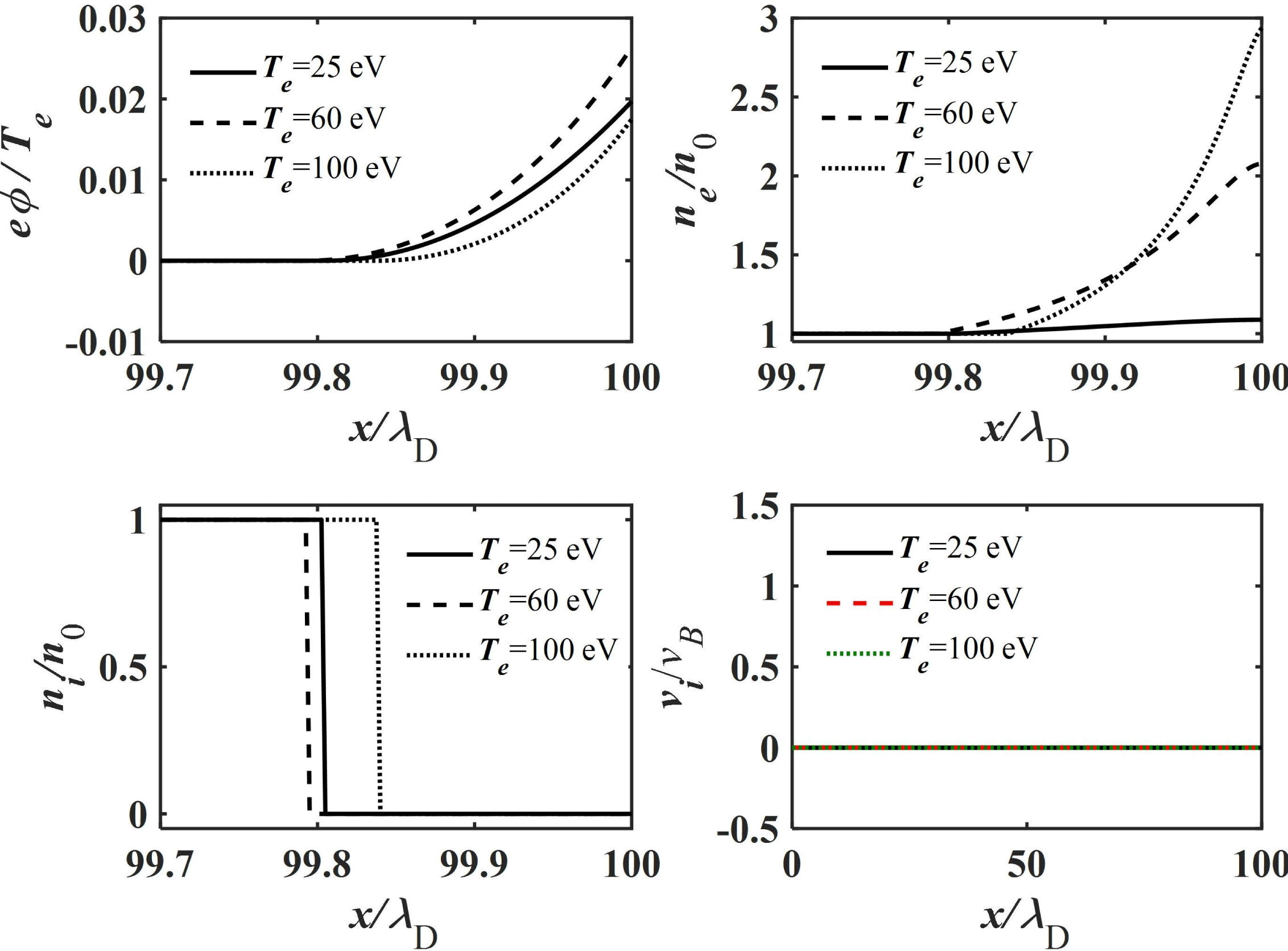
, the ions are fully reflected and the sheath becomes much narrower, scaling as the electron Debye length. We call this the ‘inverse sheath’ regime. As shown in figure 3,
 $\unicode[STIX]{x1D719}$
increases monotonically toward the wall, and
 $n_{e}$
increases too. The wall potential
 $\unicode[STIX]{x1D719}_{w}$
is just 0.01–0.03
 $T_{e}/e$
. However, it is enough to repel most of the emitted secondary electrons. The repelled secondary electrons will bombard the wall surface, thus leading to new emitted electrons, and repeat in this way, which is known as the MEE phenomenon (see figure 1
b). Therefore,
 $n_{e}$
increases sharply in the sheath region.
The steady-state distributions of electric potential
 $\unicode[STIX]{x1D719}$
, electron density
 $n_{e}$
and ion density
 $n_{i}$
and ion velocity
 $v_{i}$
in the inverse sheath for the cases of
 $T_{e}=25$
, 60, 100 eV.

Note that
 $n_{i}$
and
 $v_{i}$
are equal zero, i.e. no ion enters into the inverse sheath region. The ion density at the sheath edge changes sharply (i.e. step change). Since
 $v_{i}(0)=0$
and the plasma ions are assumed to be cold, there would be no presheath before the inverse sheath region.
2.4 Steady-state parameter distributions in an SCL sheath
When
 $T_{e}\geqslant T_{e\text{SCL}}\approx 60$
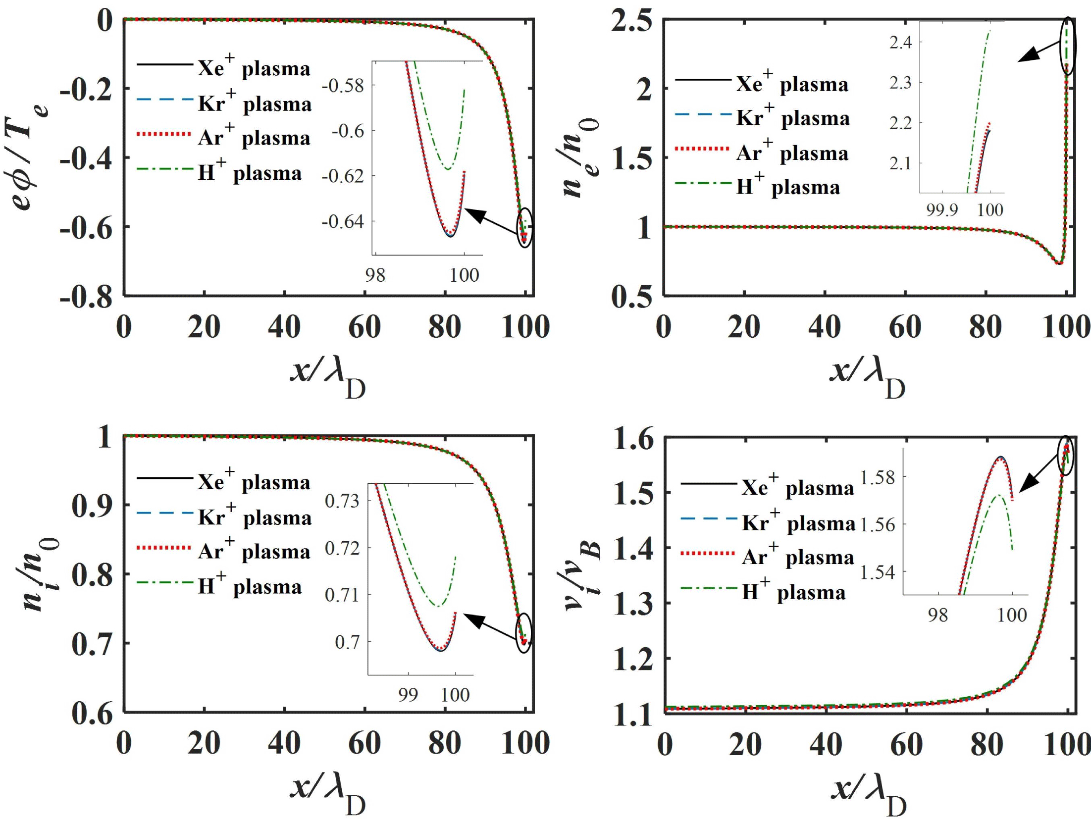
eV, excepting the solution for an inverse sheath, another solution for an SCL sheath emerges. As shown in figure 4,
 $\unicode[STIX]{x1D719}$
presents non-monotonic variation, it at first decreases to a minimum value and then increases slightly toward the wall. With such a potential distribution,
 $n_{e}$
increases sharply at the near-wall sheath region due to the MEE phenomenon. An ion entering the sheath will be accelerated at first and then decelerated by the near-wall potential increment. Therefore,
 $n_{i}$
decreases at first in the near-sheath-edge region and then increases in the near-wall sheath region based on the ion flux conservation (i.e.
 $n_{i}(x)v_{i}(x)=n_{0}v_{i0}$
).
The steady-state distributions of electric potential
 $\unicode[STIX]{x1D719}$
, electron density
 $n_{e}$
and ion density
 $n_{i}$
and ion velocity
 $v_{i}$
in the SCL sheath for the cases of a Xe+ plasma, Kr+ plasma, Ar+ plasma and H+ plasma when
 $T_{e}=60$
eV.

3 Eigenvalue problem model of an ion–electron two-stream instability in the sheath
In the model, a plasma with negative electrons and positive, single-charged, pure, cold ions is considered. To focus on finding the ion streaming instability, the source and collision terms in the model are neglected. Following the one-dimensional model described in § 2, the one-dimensional problem of an ion fluid and electron fluid is considered. Then, the fluid equations for ions and electrons are,
 $$\begin{eqnarray}\displaystyle & \displaystyle \frac{\unicode[STIX]{x2202}n_{i}}{\unicode[STIX]{x2202}t}+\frac{\unicode[STIX]{x2202}}{\unicode[STIX]{x2202}x}(n_{i}v_{i})=0, & \displaystyle\end{eqnarray}$$
 $$\begin{eqnarray}\displaystyle & \displaystyle \frac{\unicode[STIX]{x2202}n_{e}}{\unicode[STIX]{x2202}t}+\frac{\unicode[STIX]{x2202}}{\unicode[STIX]{x2202}x}(n_{e}v_{e})=0, & \displaystyle\end{eqnarray}$$
 $$\begin{eqnarray}\displaystyle & \displaystyle \frac{\unicode[STIX]{x2202}v_{i}}{\unicode[STIX]{x2202}t}+v_{i}\frac{\unicode[STIX]{x2202}v_{i}}{\unicode[STIX]{x2202}x}=-\frac{e}{m_{i}}\frac{\unicode[STIX]{x2202}\unicode[STIX]{x1D719}}{\unicode[STIX]{x2202}x}, & \displaystyle\end{eqnarray}$$
 $$\begin{eqnarray}\displaystyle & \displaystyle \frac{\unicode[STIX]{x2202}v_{e}}{\unicode[STIX]{x2202}t}+v_{e}\frac{\unicode[STIX]{x2202}v_{e}}{\unicode[STIX]{x2202}x}=\frac{e}{m_{e}}\frac{\unicode[STIX]{x2202}\unicode[STIX]{x1D719}}{\unicode[STIX]{x2202}x}-\frac{1}{m_{e}n_{e}}\frac{\unicode[STIX]{x2202}(n_{e}T_{e})}{\unicode[STIX]{x2202}x}, & \displaystyle\end{eqnarray}$$
 $$\begin{eqnarray}\displaystyle & \displaystyle \unicode[STIX]{x1D700}_{0}\frac{\unicode[STIX]{x2202}^{2}\unicode[STIX]{x1D719}}{\unicode[STIX]{x2202}x^{2}}=e(n_{e}-n_{i}). & \displaystyle\end{eqnarray}$$
3.1 Linearized eigenvalue equations
In a non-uniform plasma sheath region, with a perturbation to the steady-state equilibrium, a function of
 $f(x,t)$
can be divided into two parts as
 $f(x,t)=f_{s}(x)+\tilde{f}(x,t)$
, where
 $f_{s}(x)$
is the steady-state term and
 $\tilde{f}(x,t)$
is the perturbation term which can be written as
 $\tilde{f}(x,t)=\tilde{f}(x)\text{e}^{-\text{i}\unicode[STIX]{x1D714}t}$
. In the low frequency regime (i.e. the perturbation frequency
 $\unicode[STIX]{x1D714}\sim \unicode[STIX]{x1D714}_{\text{pi}}$
, where
 $\unicode[STIX]{x1D714}_{\text{pi}}=\sqrt{n_{0}e^{2}/m_{i}\unicode[STIX]{x1D700}_{0}}$
is the plasma ion frequency) considering the response of ions and electrons, we can obtain,
 $$\begin{eqnarray}\displaystyle & \displaystyle n_{i}(x,t)=n_{is}(x)+{\tilde{n}}_{i}(x)\text{e}^{-\text{i}\unicode[STIX]{x1D714}t}, & \displaystyle\end{eqnarray}$$
 $$\begin{eqnarray}\displaystyle & \displaystyle n_{e}(x,t)=n_{es}(x)+{\tilde{n}}_{e}(x)\text{e}^{-\text{i}\unicode[STIX]{x1D714}t}, & \displaystyle\end{eqnarray}$$
 $$\begin{eqnarray}\displaystyle & \displaystyle v_{i}(x,t)=v_{is}(x)+\tilde{v}_{i}(x)\text{e}^{-\text{i}\unicode[STIX]{x1D714}t}, & \displaystyle\end{eqnarray}$$
 $$\begin{eqnarray}\displaystyle & \displaystyle v_{e}(x,t)=v_{es}(x)+\tilde{v}_{e}(x)\text{e}^{-\text{i}\unicode[STIX]{x1D714}t}, & \displaystyle\end{eqnarray}$$
 $$\begin{eqnarray}\displaystyle & \displaystyle \unicode[STIX]{x1D719}(x,t)=\unicode[STIX]{x1D719}_{s}(x)+\tilde{\unicode[STIX]{x1D719}}(x)\text{e}^{-\text{i}\unicode[STIX]{x1D714}t}. & \displaystyle\end{eqnarray}$$
For an electron fluid, the density-inhomogeneity-induced diffusion is considered, while the temperature inhomogeneity and steady-state drift velocity are neglected (i.e.
 $\unicode[STIX]{x2202}T_{e}/\unicode[STIX]{x2202}x=0$
,
 $v_{es}=0$
) since the positive sheath electric field can only slow down the primary electrons but cannot change the configuration of the primary electron velocity distribution. Therefore, substituting equations (3.2a
)–(3.2e
) into (3.1a
)–(3.1e
), the linearized eigenvalue equations are,
 $$\begin{eqnarray}\displaystyle & \displaystyle -\text{i}\unicode[STIX]{x1D714}{\tilde{n}}_{i}+\tilde{v}_{i}\frac{\unicode[STIX]{x2202}n_{is}}{\unicode[STIX]{x2202}x}+n_{is}\frac{\unicode[STIX]{x2202}\tilde{v}_{i}}{\unicode[STIX]{x2202}x}+v_{is}\frac{\unicode[STIX]{x2202}{\tilde{n}}_{i}}{\unicode[STIX]{x2202}x}+{\tilde{n}}_{i}\frac{\unicode[STIX]{x2202}v_{is}}{\unicode[STIX]{x2202}x}=0, & \displaystyle\end{eqnarray}$$
 $$\begin{eqnarray}\displaystyle & \displaystyle -\text{i}\unicode[STIX]{x1D714}{\tilde{n}}_{e}+\tilde{v}_{e}\frac{\unicode[STIX]{x2202}n_{es}}{\unicode[STIX]{x2202}x}+n_{es}\frac{\unicode[STIX]{x2202}\tilde{v}_{e}}{\unicode[STIX]{x2202}x}=0, & \displaystyle\end{eqnarray}$$
 $$\begin{eqnarray}\displaystyle & \displaystyle -\text{i}\unicode[STIX]{x1D714}\tilde{v}_{i}+v_{is}\frac{\unicode[STIX]{x2202}\tilde{v}_{i}}{\unicode[STIX]{x2202}x}+\tilde{v}_{i}\frac{\unicode[STIX]{x2202}v_{is}}{\unicode[STIX]{x2202}x}=-\frac{e}{m_{i}}\frac{\unicode[STIX]{x2202}\tilde{\unicode[STIX]{x1D719}}}{\unicode[STIX]{x2202}x}, & \displaystyle\end{eqnarray}$$
 $$\begin{eqnarray}\displaystyle & \displaystyle -\text{i}\unicode[STIX]{x1D714}\tilde{v}_{e}=\frac{e}{m_{e}}\frac{\unicode[STIX]{x2202}\tilde{\unicode[STIX]{x1D719}}}{\unicode[STIX]{x2202}x}-\frac{T_{e}}{m_{e}n_{es}}\frac{\unicode[STIX]{x2202}{\tilde{n}}_{e}}{\unicode[STIX]{x2202}x}, & \displaystyle\end{eqnarray}$$
 $$\begin{eqnarray}\displaystyle & \displaystyle \unicode[STIX]{x1D700}_{0}\frac{\unicode[STIX]{x2202}^{2}\tilde{\unicode[STIX]{x1D719}}}{\unicode[STIX]{x2202}x^{2}}=e({\tilde{n}}_{e}-{\tilde{n}}_{i}). & \displaystyle\end{eqnarray}$$
 ${\tilde{n}}_{i}$
,
 $\tilde{v}_{i}$
,
 ${\tilde{n}}_{e}$
,
 $\tilde{v}_{e}$
and
 $\tilde{\unicode[STIX]{x1D719}}$
are the eigenfunctions, and the eigenvalue
 $\unicode[STIX]{x1D714}=\unicode[STIX]{x1D714}_{R}+\text{i}\unicode[STIX]{x1D714}_{I}$
. When the imaginary part of
 $\unicode[STIX]{x1D714}$
, i.e.
 $\unicode[STIX]{x1D714}_{I}$
is positive, there is then an instability due to the ions streaming relative to the electrons. Otherwise, the fluctuations are damped and the sheath is stable.
3.2 Dimensionless eigenvalue equations
For convenience of numerical calculation, the eigenvalue equations (3.3a )–(3.3e ) are normalized with the following dimensionless quantities:
 $$\begin{eqnarray}\displaystyle \left.\begin{array}{@{}c@{}}\displaystyle {\tilde{N}}_{i}={\tilde{n}}_{i}/n_{0},\quad {\tilde{N}}_{e}={\tilde{n}}_{e}/n_{0},\quad N_{is}=n_{is}/n_{0},\quad N_{es}=n_{es}/n_{0},\quad \tilde{V}_{i}=\tilde{v}_{i}/v_{B},\\ \displaystyle \tilde{V}_{e}=\tilde{v}_{e}/v_{B},\quad V_{is}=v_{is}/v_{B},\quad \tilde{\unicode[STIX]{x1D6F7}}=e\tilde{\unicode[STIX]{x1D719}}/T_{e},\quad \unicode[STIX]{x1D709}=x/\unicode[STIX]{x1D706}_{\text{D}},\quad \overline{\unicode[STIX]{x1D714}}=\unicode[STIX]{x1D714}/\unicode[STIX]{x1D714}_{\text{pi}}.\end{array}\right\} & & \displaystyle\end{eqnarray}$$
Then, the normalized eigenvalue equations are,
 $$\begin{eqnarray}\displaystyle & \displaystyle -\text{i}\overline{\unicode[STIX]{x1D714}}{\tilde{N}}_{i}+\tilde{V}_{i}\frac{\unicode[STIX]{x2202}N_{is}}{\unicode[STIX]{x2202}\unicode[STIX]{x1D709}}+N_{is}\frac{\unicode[STIX]{x2202}\tilde{V}_{i}}{\unicode[STIX]{x2202}\unicode[STIX]{x1D709}}+V_{is}\frac{\unicode[STIX]{x2202}{\tilde{N}}_{i}}{\unicode[STIX]{x2202}\unicode[STIX]{x1D709}}+{\tilde{N}}_{i}\frac{\unicode[STIX]{x2202}V_{is}}{\unicode[STIX]{x2202}\unicode[STIX]{x1D709}}=0, & \displaystyle\end{eqnarray}$$
 $$\begin{eqnarray}\displaystyle & \displaystyle -\text{i}\overline{\unicode[STIX]{x1D714}}{\tilde{N}}_{e}+\tilde{V}_{e}\frac{\unicode[STIX]{x2202}N_{es}}{\unicode[STIX]{x2202}\unicode[STIX]{x1D709}}+N_{es}\frac{\unicode[STIX]{x2202}\tilde{V}_{e}}{\unicode[STIX]{x2202}\unicode[STIX]{x1D709}}=0, & \displaystyle\end{eqnarray}$$
 $$\begin{eqnarray}\displaystyle & \displaystyle -\text{i}\overline{\unicode[STIX]{x1D714}}\tilde{V}_{i}+V_{is}\frac{\unicode[STIX]{x2202}\tilde{V}_{i}}{\unicode[STIX]{x2202}\unicode[STIX]{x1D709}}+\tilde{V}_{i}\frac{\unicode[STIX]{x2202}V_{is}}{\unicode[STIX]{x2202}\unicode[STIX]{x1D709}}=-\frac{\unicode[STIX]{x2202}\tilde{\unicode[STIX]{x1D6F7}}}{\unicode[STIX]{x2202}\unicode[STIX]{x1D709}}, & \displaystyle\end{eqnarray}$$
 $$\begin{eqnarray}\displaystyle & \displaystyle -\text{i}\overline{\unicode[STIX]{x1D714}}\tilde{V}_{e}=\frac{m_{i}}{m_{e}}\frac{\unicode[STIX]{x2202}\tilde{\unicode[STIX]{x1D6F7}}}{\unicode[STIX]{x2202}\unicode[STIX]{x1D709}}-\frac{m_{i}}{m_{e}N_{es}}\frac{\unicode[STIX]{x2202}{\tilde{N}}_{e}}{\unicode[STIX]{x2202}\unicode[STIX]{x1D709}}, & \displaystyle\end{eqnarray}$$
 $$\begin{eqnarray}\displaystyle & \displaystyle \frac{\unicode[STIX]{x2202}^{2}\tilde{\unicode[STIX]{x1D6F7}}}{\unicode[STIX]{x2202}\unicode[STIX]{x1D709}^{2}}={\tilde{N}}_{e}-{\tilde{N}}_{i}. & \displaystyle\end{eqnarray}$$
4 Numerical results and discussion
In this section, the eigenvalue equations will be solved numerically. By applying the steady-state solutions in § 2 to (3.5a
)–(3.5e
), the linear eigenvalue problem can be solved easily. To consider instabilities in the sheath regions, we integrate the equations from the plasma–sheath interface at approximately
 $\unicode[STIX]{x1D709}=60$
, with the boundary conditions
 $$\begin{eqnarray}\displaystyle \left.\begin{array}{@{}c@{}}\displaystyle {\tilde{N}}_{i}(60)=0,\quad \text{d}{\tilde{N}}_{i}/\text{d}\unicode[STIX]{x1D709}|_{\unicode[STIX]{x1D709}=60}=0,\\ \displaystyle {\tilde{N}}_{e}(60)=0,\quad \text{d}{\tilde{N}}_{e}/\text{d}\unicode[STIX]{x1D709}|_{\unicode[STIX]{x1D709}=60}=0,\\ \displaystyle \tilde{V}_{i}(60)=0,\quad \text{d}\tilde{V}_{i}/\text{d}\unicode[STIX]{x1D709}|_{\unicode[STIX]{x1D709}=60}=0,\\ \displaystyle \tilde{V}_{e}(60)=0,\quad \text{d}\tilde{V}_{e}/\text{d}\unicode[STIX]{x1D709}|_{\unicode[STIX]{x1D709}=60}=0,\\ \tilde{\unicode[STIX]{x1D6F7}}(60)=0,\quad \text{d}\tilde{\unicode[STIX]{x1D6F7}}/\text{d}\unicode[STIX]{x1D709}|_{\unicode[STIX]{x1D709}=60}=\unicode[STIX]{x1D6FF},\end{array}\right\} & & \displaystyle\end{eqnarray}$$
where
 $|\unicode[STIX]{x1D6FF}|\ll 1$
is a non-zero boundary condition.
On the wall
 $\tilde{\unicode[STIX]{x1D6F7}}(L)$
is set free but is limited to the linear regime with
 $\tilde{\unicode[STIX]{x1D6F7}}(L)\ll 1$
. Then, for arbitrary
 $\overline{\unicode[STIX]{x1D714}}$
, we can integrate equations (3.5a
)–(3.5e
) along the x direction. In particular, if
 $\tilde{\unicode[STIX]{x1D6F7}}(L)$
is convergent to zero in the neighbourhood of
 $\overline{\unicode[STIX]{x1D714}}$
, we can obtain the linear solutions of the eigenfunctions
 $\tilde{\unicode[STIX]{x1D6F7}}$
,
 ${\tilde{N}}_{i}$
and
 $\tilde{V}_{i}$
,
 ${\tilde{N}}_{e}$
and
 $\tilde{V}_{e}$
and the dimensionless growth rate or damping
 $\overline{\unicode[STIX]{x1D6FE}}=\unicode[STIX]{x1D6FE}/\unicode[STIX]{x1D714}_{\text{pi}}=\overline{\unicode[STIX]{x1D714}}_{I}$
.
4.1 Ion–electron two-stream instability in a classic sheath
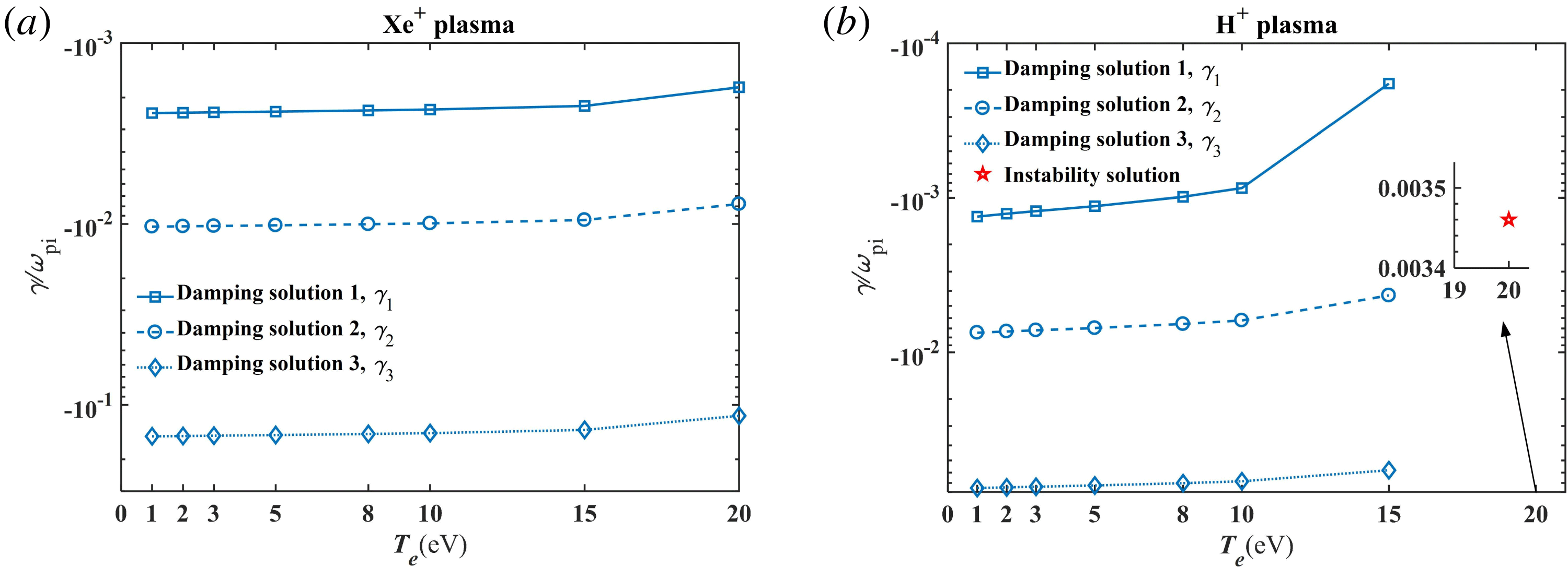
Figure 5(a) shows the eigenvalues for a Xe+ plasma (heavier ion), with the cases of
 $T_{e}=1$
, 2, 3, 5, 8, 10, 15, 20 eV. Three damping solutions, i.e.
 $\unicode[STIX]{x1D6FE}_{1}$
,
 $\unicode[STIX]{x1D6FE}_{2}$
and
 $\unicode[STIX]{x1D6FE}_{3}$
are found;
 $\unicode[STIX]{x1D6FE}_{1}$
is only approximately two tenths of a per cent of the plasma ion frequency,
 $\unicode[STIX]{x1D6FE}_{2}$
is approximately one per cent of the plasma ion frequency, while
 $\unicode[STIX]{x1D6FE}_{3}$
is more than ten per cent of the plasma ion frequency; as
 $T_{e}$
increases, the three damping solutions increase slowly.
The three damping solutions, namely
 $\unicode[STIX]{x1D6FE}_{1}$
,
 $\unicode[STIX]{x1D6FE}_{2}$
and
 $\unicode[STIX]{x1D6FE}_{3}$
, under the classic sheath regime versus the Maxwellian plasma electron temperature
 $T_{e}$
for the cases of (a) Xe+ plasma, (b) H+ plasma. Note that there is an instability solution for a H+ plasma when
 $T_{e}=20$
eV.

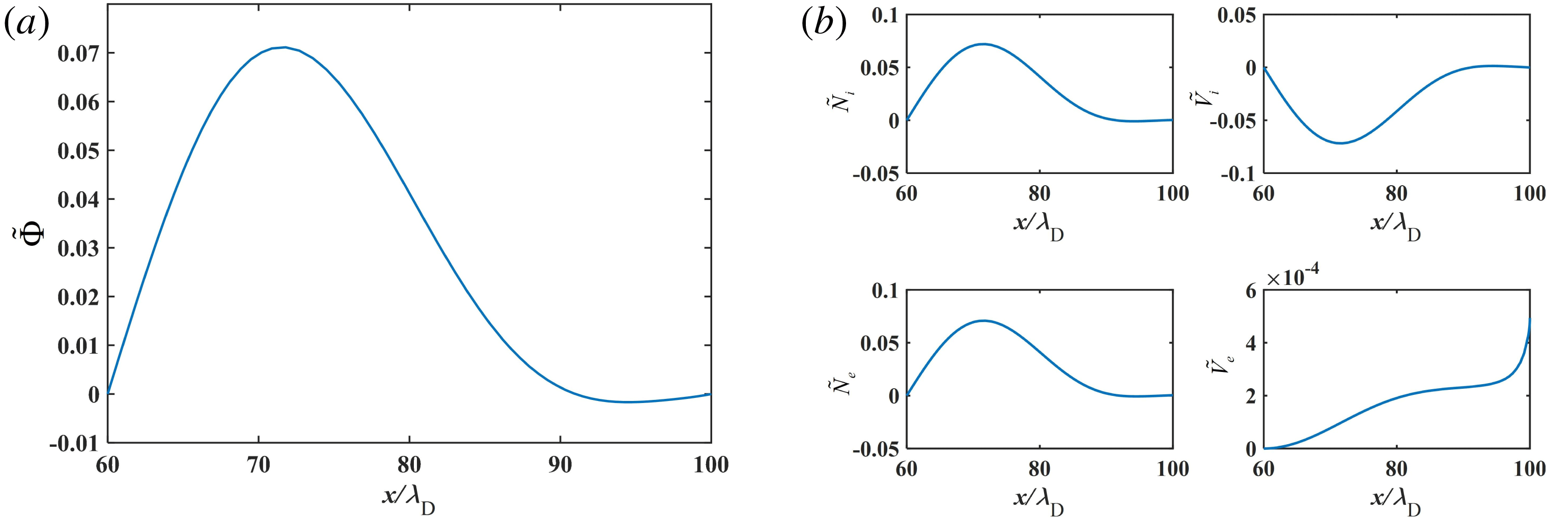
The eigenfunction distributions of (a)
 $\tilde{\unicode[STIX]{x1D6F7}}$
, and (b)
 ${\tilde{N}}_{i}$
,
 $\tilde{V}_{i}$
,
 ${\tilde{N}}_{e}$
and
 $\tilde{V}_{e}$
under the classic sheath regime, with the damping solution 1, i.e.
 $\unicode[STIX]{x1D6FE}_{1}=-0.000182402\unicode[STIX]{x1D714}_{\text{pi}}$
, for the case of a H+ plasma,
 $T_{e}=15$
eV.

Figure 5(b) shows the eigenvalues for a H+ plasma (lighter ion). The three damping solutions are also found for the cases of
 $T_{e}\leqslant 15$
eV;
 $\unicode[STIX]{x1D6FE}_{1}$
,
 $\unicode[STIX]{x1D6FE}_{2}$
and
 $\unicode[STIX]{x1D6FE}_{3}$
are bigger than those of a Xe+ plasma; as
 $T_{e}$
increases, the three damping solutions increase faster than those of a Xe+ plasma. The eigenfunctions
 $\tilde{\unicode[STIX]{x1D6F7}}$
,
 ${\tilde{N}}_{i}$
and
 $\tilde{V}_{i}$
,
 ${\tilde{N}}_{e}$
and
 $\tilde{V}_{e}$
corresponding to the three damping solutions, namely
 $\unicode[STIX]{x1D6FE}_{1}=-0.000182402\unicode[STIX]{x1D714}_{\text{pi}}$
,
 $\unicode[STIX]{x1D6FE}_{2}=-0.004279169\unicode[STIX]{x1D714}_{\text{pi}}$
and
 $\unicode[STIX]{x1D6FE}_{3}=-0.05785627\unicode[STIX]{x1D714}_{\text{pi}}$
, for the case of a H+ plasma,
 $T_{e}=15$
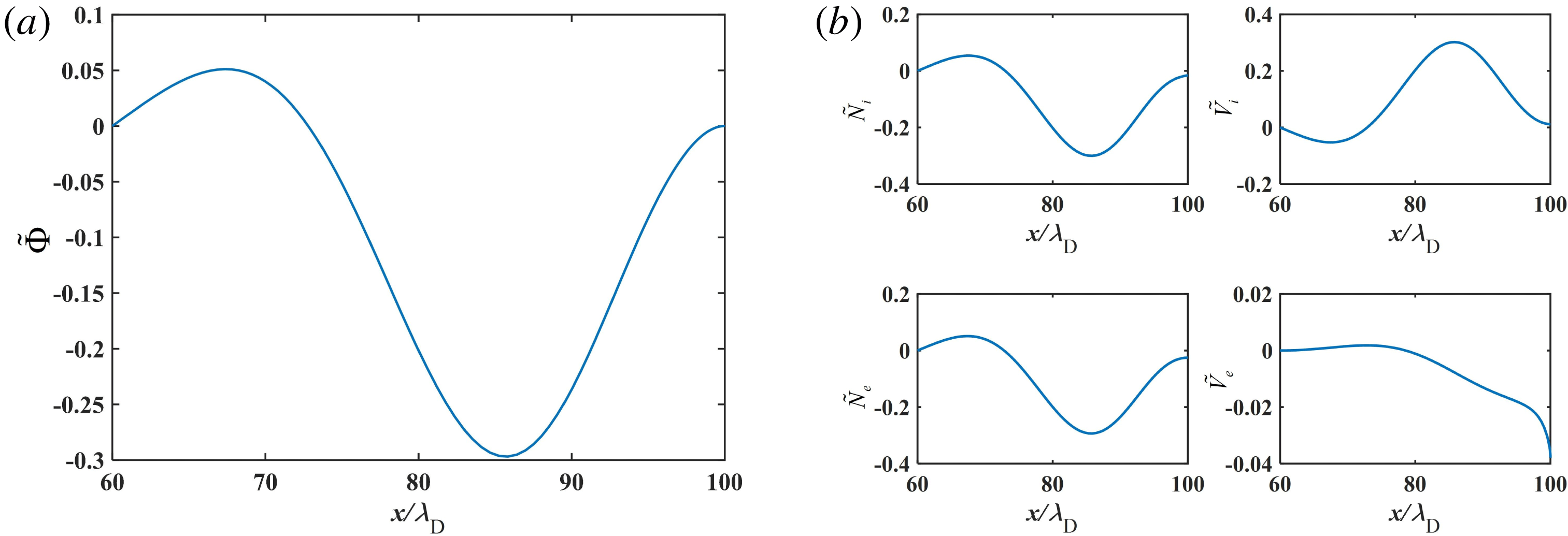
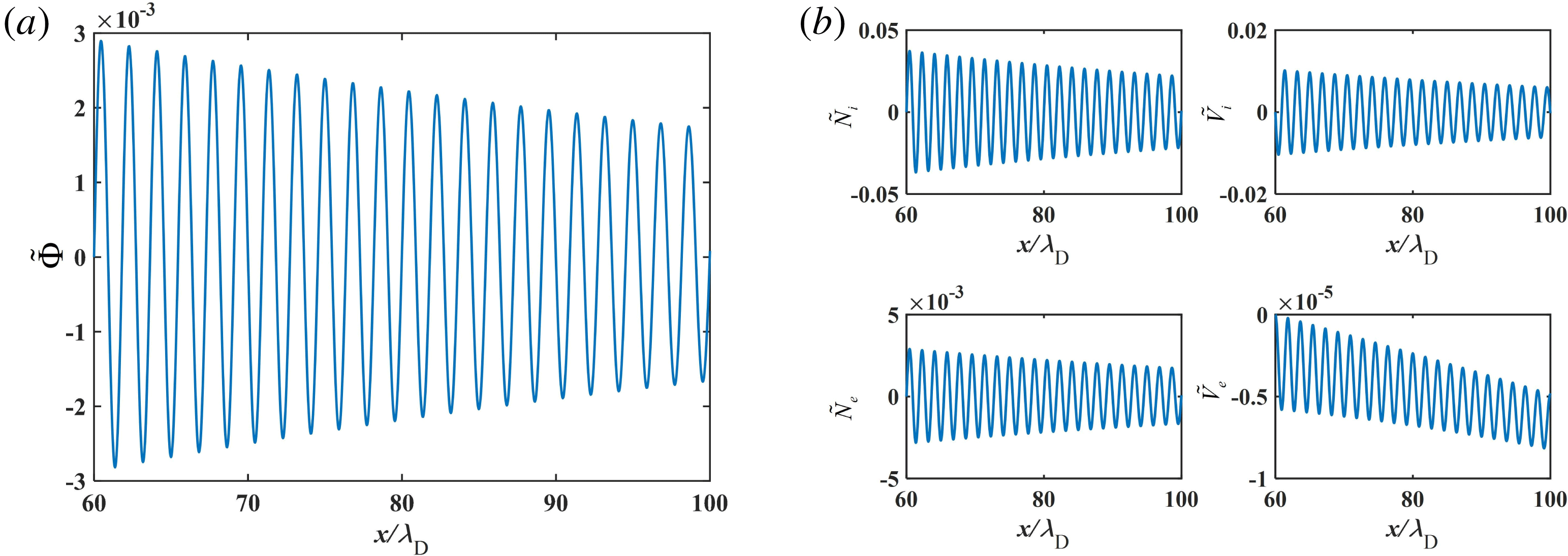
eV, are respectively shown in figures 6–8. We can see that these eigenfunctions are different, in particular, the amplitude of variation increases significantly as the damping solution decreases. And when
 $T_{e}=20$
eV, the damping solution disappears, and instead a growth-rate solution appears. The eigenfunctions
 $\tilde{\unicode[STIX]{x1D6F7}}$
,
 ${\tilde{N}}_{i}$
and
 $\tilde{V}_{i}$
,
 ${\tilde{N}}_{e}$
and
 $\tilde{V}_{e}$
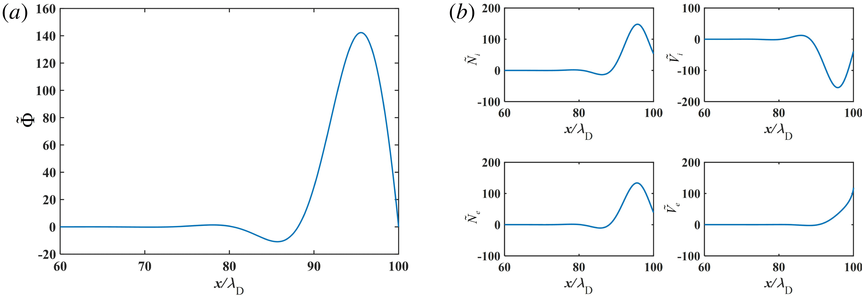
corresponding to the instability solution, namely
 $\unicode[STIX]{x1D6FE}=0.00346\unicode[STIX]{x1D714}_{\text{pi}}$
, for the case of a H+ plasma,
 $T_{e}=20$
eV, are shown in figure 9. We note that these eigenfunctions present rapid variation in the sheath region.
The eigenfunction distributions of (a)
 $\tilde{\unicode[STIX]{x1D6F7}}$
, and (b)
 ${\tilde{N}}_{i}$
,
 $\tilde{V}_{i}$
,
 ${\tilde{N}}_{e}$
and
 $\tilde{V}_{e}$
under the classic sheath regime, with the damping solution 2, i.e.
 $\unicode[STIX]{x1D6FE}_{2}=-0.004279169\unicode[STIX]{x1D714}_{\text{pi}}$
, for the case of a H+ plasma,
 $T_{e}=15$
eV.

The eigenfunction distributions of (a)
 $\tilde{\unicode[STIX]{x1D6F7}}$
, and (b)
 ${\tilde{N}}_{i}$
,
 $\tilde{V}_{i}$
,
 ${\tilde{N}}_{e}$
and
 $\tilde{V}_{e}$
under the classic sheath regime, with the damping solution 3, i.e.
 $\unicode[STIX]{x1D6FE}_{3}=-0.05785627\unicode[STIX]{x1D714}_{\text{pi}}$
, for the case of a H+ plasma,
 $T_{e}=15$
eV.

The eigenfunction distributions of (a)
 $\tilde{\unicode[STIX]{x1D6F7}}$
, and (b)
 ${\tilde{N}}_{i}$
,
 $\tilde{V}_{i}$
,
 ${\tilde{N}}_{e}$
and
 $\tilde{V}_{e}$
under the classic sheath regime, with the growth rate
 $\unicode[STIX]{x1D6FE}=0.00346\unicode[STIX]{x1D714}_{\text{pi}}$
, for the case of a H+ plasma,
 $T_{e}=20$
eV.

The results in figures 5(a) and 5(b) indicate that both the ion mass and
 $T_{e}$
have a significant influence on the ion–electron two-stream instability. In fact, the heavier ion has a higher dimensionless drift velocity than that of the lighter ion, as shown in figure 2(d). Therefore, due to the higher drift energy and bigger inertia of the heavier ions, the ion–electron stream in a sheath with a heavier ion species should have a stronger stability, i.e. smaller damping solution. Also, we can see from figure 2(a–d), that the inhomogeneity of the sheath parameters decreases significantly as
 $T_{e}$
increases. As a result, the three damping solutions increase with the increment of
 $T_{e}$
. In particular, when
 $T_{e}\rightarrow T_{ec}$
, e.g.
 $T_{e}=20$
eV, for lighter ions (i.e. a H+ plasma), the wall potential
 $\unicode[STIX]{x1D719}_{w}=-3.38\times 10^{-4}T_{e}/e$
and ion drift energy at the sheath edge
 $E=0.0386T_{e}$
are very close to zero, resulting in a very small inhomogeneity of the sheath (i.e. the sheath approximately degenerates into a uniform quasi-neutral region). In this case, the ion–electron two-stream instability in the sheath region is approximately equivalent to that in a uniform plasma region, i.e. the instability growth rate can be roughly estimated
 $\unicode[STIX]{x1D6FE}\sim kv_{i0}\unicode[STIX]{x1D714}_{\text{pi}}/\unicode[STIX]{x1D714}_{\text{pe}}$
. For our simulation parameters,
 $kv_{i0}=k\sqrt{2E/m_{i}}=0.2778kv_{B}\sim 0.2778v_{B}/\unicode[STIX]{x1D706}_{\text{D}}\sim 0.2778\unicode[STIX]{x1D714}_{\text{pi}}$
, we can get the estimate of
 $\unicode[STIX]{x1D6FE}/\unicode[STIX]{x1D714}_{\text{pi}}\sim 0.2778\sqrt{m_{e}/m_{i}}\sim 10^{-3}$
, of the same order as the instability growth rate of the red star shown in figure 5(b).
At the sheath-structure transition point, i.e. the case of
 $T_{e}=T_{ec}$
in figure 2, the sheath disappears: (i) the electron density equals the ion density; (ii) the electric potential and the ion velocity equal zero.
4.2 Ion–electron two-stream instability in inverse and SCL sheaths
Under the inverse sheath regime, due to the steady-state ion density and velocity being equal to zero in the whole sheath region (see figure 3), the normalized eigenvalue equations (3.5a
)–(3.5e
) can be significantly simplified and the dimensionless growth rate equals zero. This indicates that, for the case of an entirely inverse sheath with no ions in the sheath region, the ion streaming instability cannot propagate there, and thus
 $\unicode[STIX]{x1D6FE}=0$
.
Under the SCL sheath regime, the steady-state parameters in the sheath region present non-monotonic distributions, as shown in figure 4. Although the near-wall electric potential increment is very small, the remarkably increased electron density distribution in the near-wall region may have a significant influence on the solutions of the eigenvalue equations, in comparison with that of a classic sheath (see figure 2).
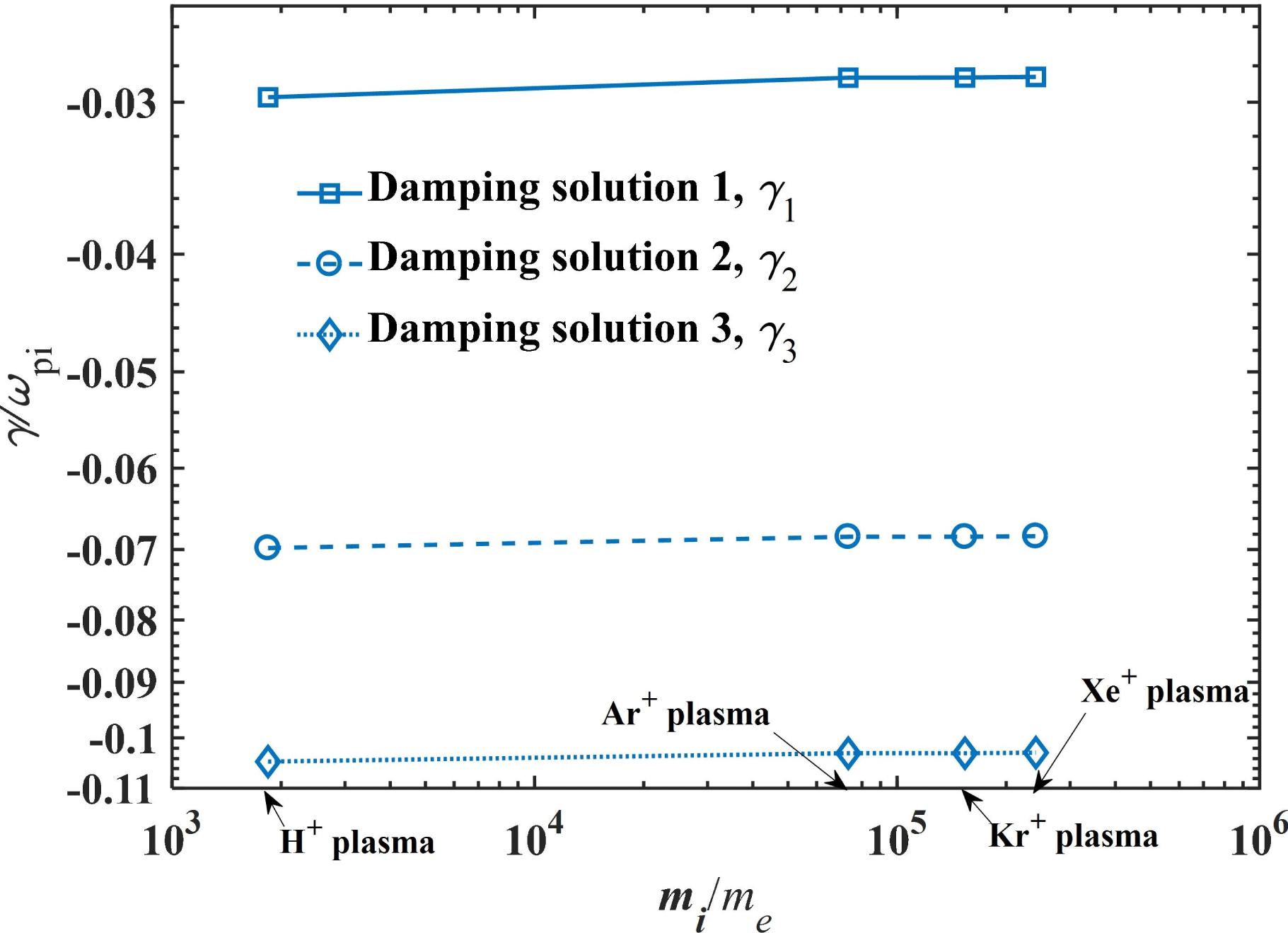
As shown in figure 10, the three damping solutions
 $\unicode[STIX]{x1D6FE}_{1}$
,
 $\unicode[STIX]{x1D6FE}_{2}$
and
 $\unicode[STIX]{x1D6FE}_{3}$
in the SCL sheath are obviously smaller than those under a classic sheath (see figure 5
b). The three damping solutions in the SCL sheath are nearly independent of the ion mass, i.e.
 $\overline{\unicode[STIX]{x1D6FE}}_{1}\approx -3\,\%$
,
 $\overline{\unicode[STIX]{x1D6FE}}_{2}\approx -7\,\%$
and
 $\overline{\unicode[STIX]{x1D6FE}}_{3}\approx -10\,\%$
, since the steady-state distributions of ion density, electron density and ion velocity are very close for different cases of ion mass (see figure 4).
The three damping solutions, namely
 $\unicode[STIX]{x1D6FE}_{1}$
,
 $\unicode[STIX]{x1D6FE}_{2}$
and
 $\unicode[STIX]{x1D6FE}_{3}$
, under the SCL sheath regime versus the mass ratio
 $m_{i}/m_{e}$
when
 $T_{e}=60$
eV.

5 Conclusions
In summary, the ion–electron two-stream instability in three existing types of plasma sheath structure, i.e. classic, inverse and SCL sheaths formed between a Maxwellian plasma source and a dielectric wall with SEE is investigated as an eigenvalue problem. The steady-state parameter distributions in the three sheaths with pure, single-charged, positive, cold ions have been solved by the 1D3V, collisionless kinetic sheath model (Qing & Wu Reference Qing and Wu2018; Qing & Zhao Reference Qing and Zhao2018), within a wide range of Maxwellian plasma electron temperature
 $T_{e}$
. The eigenvalue equations of the perturbations of electric potential, ion density and velocity and electron density and velocity in the background plasma system have been derived. The eigenfunctions through the three sheaths and the corresponding eigenvalues are solved numerically. Under the classic sheath regime (i.e.
 $T_{e}<T_{ec}$
(the first threshold)), it is found that both
 $T_{e}$
and ion species have significant influence on the dimensionless solution
 $\overline{\unicode[STIX]{x1D6FE}}$
: (i) there are three damping solutions, i.e.
 $\overline{\unicode[STIX]{x1D6FE}}_{1}$
,
 $\overline{\unicode[STIX]{x1D6FE}}_{2}$
and
 $\overline{\unicode[STIX]{x1D6FE}}_{3}$
(
 $0>\overline{\unicode[STIX]{x1D6FE}}_{1}>\overline{\unicode[STIX]{x1D6FE}}_{2}>\overline{\unicode[STIX]{x1D6FE}}_{3}$
) for most cases of
 $T_{e}<T_{ec}$
(i.e.
 $\unicode[STIX]{x1D6E4}<1$
), but there is only one growth-rate solution
 $\unicode[STIX]{x1D6FE}$
when
 $T_{e}\rightarrow T_{ec}$
(i.e. the inhomogeneity of the sheath is very weak); (ii) as
 $m_{i}$
increases, the three damping solutions increase.
This indicates that the inhomogeneity in the sheath has a tendency to enhance the stability of the sheath itself. When
 $T_{e}$
increases to
 $T_{ec}$
gradually, the inhomogeneity becomes weaker and weaker, and eventually the sheath can be approximately equivalent to a quasi-neutral plasma region which has a very small growth-rate solution of ion–electron two-stream instability.
Due to the ion mass having a very weak influence on the inhomogeneity of the SCL sheath, i.e. it only slightly changes the steady-state dimensionless parameter distributions of ion density, electron density and ion velocity, the three damping solutions present negligible variation as ion mass increases, i.e.
 $\overline{\unicode[STIX]{x1D6FE}}_{1}\approx -3\,\%$
,
 $\overline{\unicode[STIX]{x1D6FE}}_{2}\approx -7\,\%$
and
 $\overline{\unicode[STIX]{x1D6FE}}_{3}\approx -10\,\%$
.
Under the inverse sheath regime,
 $\overline{\unicode[STIX]{x1D6FE}}=0$
since there are no background ions in the sheath region (i.e. the steady-state ion density and velocity are equal to zero in the whole sheath region). However, for a real plasma, the ions are not cold, i.e. a minor portion of ions with enough high velocity would reach the dielectric wall, and thus the ion–electron two-stream instability may still exist. We leave this investigation to future work.
Acknowledgement
This work was supported by the National Natural Science Foundation of China (grant no. 11605018 and 11975062).