Nomenclature
- Ob
-
Reference point of the base
- Ob
-
Reference point of the base
- Op
-
Reference point of the platform
- Sb (Ob, x b, y b, z b)
-
Reference system fixed to the base
- Sp (Op, x b, y b, z b)
-
Reference system fixed to the platform.
- S1i (Ai, x i1, y i1, z i1)
-
Frame attached to the link (2) in the i-th leg
- S2i (Fi, x i3, y i2, z i2)
-
Frame attached to the bars (3) in the i-th leg
- S3i (Fi, x i3, y i1, z i3)
-
Frame describing the orientation of the parallelogram plane (Σ)in the i-th leg αi Angular position of the i-th leg
-
 $\unicode{x03C6}$
1i,
$\unicode{x03C6}$
2i,
$\unicode{x03C6}$
3i
-
Three angles defining the configuration of the i-th leg
- rb
-
Radius of the base
- rp
-
Radius of the platform
-
$\unicode{x03B8}$
1
-
Orientation error of the platform around x b-axis
-
$\unicode{x03B8}$
2
-
Orientation error of the platform around y b-axis
-
$\unicode{x03B8}$
3
-
Orientation error of the platform around z b-axis
- l2
-
Length of the link
- l3
-
Length of the bars
- a
-
Width of the parallelogram
- λ
-
Half of the pin length of the revolute joint
-
$\unicode{x025B}$
dji
-
Radial clearance in the j-th revolute joint in the i-th leg
-
$\unicode{x025B}$
aji
-
Axial clearance in the j-th revolute joint in the i-th leg
-
$\unicode{x025B}$
ji
-
Clearance in the j-th spherical joint in the i-th leg
-
$\unicode{x1D6D5}$
ext
-
External wrenches applied to the reference point of the platform Op
-
$\unicode{x1D6D5}$
ji
-
wrench transmitted by the j-th joint in the i-th leg
-
$\boldsymbol{\Delta}\unicode{x1D6C5}$
ji
-
Local pose error due to the clearances in the j-th joint in the i-th leg
-
$\boldsymbol{\Delta\Gamma}$
-
Pose error (position and orientation errors) of the platform


1. Introduction
Parallel manipulators with less than six Degrees of Freedom (DOF) have attracted more attention thanks to their improved characteristics such as high accuracy and rigidity. In particular, 3-DOF parallel mechanisms, which provide a pure translation to the platform [Reference Romdhane, Affi and Fayet1–Reference Clavel3], a pure rotation [Reference Kh. Al-Widyan and Angeles4, Reference Chaker, Mlika, Laribib, Romdhane and Zeghloul5] or both of them [Reference ArunSrivatsan and Bandyopadhyay6, Reference Wang, Xu, Guan and Zhi7], have been studied in the literature.
The accuracy of parallel mechanism can be altered by the uncertainties of the geometric parameters, joint clearances or both of them [Reference Kh. Al-Widyan and Angeles4, Reference Chaker, Mlika, Laribib, Romdhane and Zeghloul5, Reference Ding, Lyu, Da, Wang and Chirikjian8–Reference Liu, Lu and Ding14]. Indeed, Al-Widyan et al. [Reference Kh. Al-Widyan and Angeles4] proposed a statistical approach to determine the optimum clearances of the unactuated cylindrical joints for the 3-DOF spherical manipulators. Using a screw theory method, Chaker et al. [Reference Chaker, Mlika, Laribib, Romdhane and Zeghloul5] determined the pose error of a 3-RCC spherical parallel manipulator due to the geometric parameters uncertainties and joint clearances. Ding et al. [Reference Ding, Lyu, Da, Wang and Chirikjian8] presented a geometric method to estimate the error space of 3-DOF planar mechanisms by considering the joint clearances and actuator errors uncertainty. In fact, the Interval Analysis method has been used to verify the efficiency of this method. The static model of the isostatic parallel manipulator and the virtual work principle have been adopted to determine an analytical model of the pose error of the platform due to the clearance in the passive joints [Reference Chebbi, Affi and Romdhane2, Reference Chebbi, Chouaibi, Affi and Romdhane9–Reference Chouaibi, Chebbi, Affi and Romdhane11]. Sun et al. [Reference Sun and Chen12] considered the epistemic and random uncertainty to introduce a general method of kinematic accuracy analysis of mechanisms with clearance. Zhan et al. [Reference Zhan, Zhang, Jian and Zhang13] developed an analytical method to analyze the motion reliability of a planar parallel manipulator (PPM) with parameter uncertainties. The total motion error of the manipulator is the sum of two error types. One caused by only random variables (the geometric variables of the linkages) and the other caused by only interval variables (the joint clearance). Liu et al. [Reference Liu, Lu and Ding14] presented the error equivalent model of the revolute joint with clearances by using the virtual bar method. This model considered the radial and axial clearances to compute the error in the revolute joint.
In order to help the designer to choose a better structure, it is necessary to present a comparison analysis. Various earlier studies have focused on comparison of PPMs. For example, Binaud et al. [Reference Binaud, Caro and Wenger15, Reference Binaud, Caro and Wenger16] presented a methodology to compare PPMs based on the sensitivity coefficients of the platform pose to variations in their design parameters and workspace size. Wu et al. [Reference Wu, Li, Wang and Wang17] developed a comparison method based on the conditioning, velocity, payload and stiffness to compare the performance of PPMs. They took into consideration the well-conditioned workspace, stiffness and inertia properties. Zhan et al. [Reference Zhan, Zhang, Zhang and Chen18] presented a comparison study of PPMs with interval joint clearances by using the Global Conditioning Index, Local Conditioning Index and motion reliability. The uncertainties of manufacturing and inputs were also scrutinized. Quintero et al. [Reference Quintero, Mejia and Diaz-Rodriguez19] proposed a comparative analysis of the sensitivity in the end-effector position of PPMs with 2-DOF due to the joint clearances.
Due to the fast development, researchers have shown an interest in comparing the performance of TPMs. Indeed, Tsai et al. [Reference Tsai and Joshi20, Reference Joshi and Tsai21] presented a comparison study of three (DOF) translational parallel manipulators. The maximum workspace, the stiffness and inertia properties are used as criteria to compare four 3-DOF TPMs. Hu et al. [Reference Hu, Yao, Wu and Y.Lu22] presented a comparison study of singularity configuration, constrained forces/torques situations and stiffness of two 3-UPU parallel manipulators which have identical pure translational DOFs. Prause et al. [Reference Prause, Eddine and Corves23] used force, velocity, power, dexterity and accuracy as criteria to evaluate and compare the performance of symmetrical parallel kinematic machines with three translational DOF. Nayak [Reference Nayak, Caro and Wenger24] used the singularity-free workspace, the parasitic motions and complexity to compare the 3-[PP]S parallel manipulators under special conditions. Ben Hamida et al. [Reference Hamida, Laribi, Mlika, Romdhane and Zeghloul25] introduces a performance evaluation of four TPMs by using global dexterity and compactness as criteria to compare the performances of structures.
As described previously, it should be noted that the available research works have mainly focused on the comparison of accuracy of TPMs without considering the orientation errors due to joint clearances. Therefore, in this paper, we propose a new method to compare the accuracy of two isostatic 3-DOFs TPMs based on the analytical model of the orientation errors due to joint clearances. For this reason, two criteria are used. The first one is the maximum orientation errors estimated by solving an optimization problem of the analytical model. The second one is the condition index, which is used to analyze the sensitivity of orientation errors to variations in the geometric parameters and joint clearances of manipulators. The advantage of this method is taken into consideration the joint clearances, the geometric parameters and the external wrenches applied to the platform in order to compute the maximum and the sensitivity of the orientation errors.
Hence, the manuscript is organized as follows. In Sections 2 and 3, the kinematic and the static models of the two translational parallel manipulators are developed, respectively. In Section 4, the model that determines the orientation error of the manipulator is presented in an analytical form. In Section 5, two indices are suggested to compare two 3-DOF TPMs based on the analytical model of the orientation error. The first index is the maximum orientation errors. The second index is the sensitivity of orientation errors, which is divided in two parts, one related to the sensitivity of the orientation errors to the geometric parameters and another one related to the sensitivity of the orientation errors to the joint clearances. Finally, a comparison study of the DELTA robot and the RAF manipulator is carried out and some interpretations are concluded. The DELTA robot is one of the most well-known translational parallel manipulators [Reference Clavel3]. Many studies have been done in the literature on the optimization of this manipulator [Reference Laribi, Romdhane and Zeghloul26–28]. Laribi et al. [Reference Laribi, Romdhane and Zeghloul26], proposed an optimal design for the DELTA robot to have a specified workspace. A genetic algorithm was used to solve the optimization problem. Zhao [Reference Zhao27] proposed a methodology of the dynamic optimum design of the DELTA robot while considering an isotropic property. Kelaiaia et al. [28] proposed an approach of multi-objective optimization of the different criteria of performance, such as stiffness, the kinematic and dynamic performances using the genetic algorithms. The 3-DOF TPM (RAF) was proposed by Romdhane et al. [Reference Romdhane, Affi and Fayet1]. Chebbi et al. [Reference Chebbi, Chouaibi, Affi and Romdhane9] presented a sensitivity analysis and prediction of the orientation error limits of the RAF robot. An algorithm based on the interval analysis was used to predict the bounds of the orientation error of the manipulator. Affi et al. [Reference Affi and Romdhane29] developed an analytical model that computes the orientation error of the RAF robot. Laribi et al. [Reference Laribi et al.30] proposed a procedure based on the genetic algorithm for the optimal design of the RAF robot.
2. Kinematic model of the parallel manipulatos
2.1. Architecture of the parallel manipulators
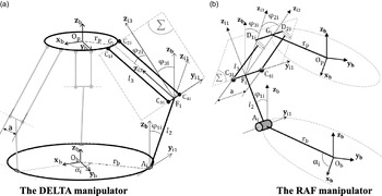
The 3-DOF translational parallel manipulator DELTA was proposed by Clavel [Reference Clavel3]. As shown in Fig. 1(a), the considered manipulator is composed of a platform connected to the base by three kinematic legs. Each i-th leg is composed of a link (2) connected to the base by an active revolute pair (Ai) with axis Δi. Two bars (3) and (3′) are connected to the link (2) by two spherical joints centered at C3i and C4i. The line C3iC4i is taken parallel to Δi. These two bars (3) and (3′) are also connected to the moving platform (4) by two spherical joints centered at C1i and C2i. The points C1iC2iC3iC4i form a parallelogram structure. The points Gi and Fi correspond to the middles of C1iC2i and C3iC4i, respectively.
Architecture of two 3-DOF translational parallel manipulators.

The 3-Translational Parallel Manipulator (RAF) was proposed by Romdhane et al. [Reference Romdhane, Affi and Fayet1] (Fig. 1(b)). The platform (4) is connected to the base (1) by three active legs of type SPS (S and P stand for spherical and active prismatic pairs, respectively) and two passive kinematic legs (PKLs), which eliminate all possible rotations of the platform with respect to the base. Each i-th PKL is composed of a link (2) connected to the base (1) by a revolute pair (Ai) with axis Δi. Two bars (3) and (3
 $^{\prime}$
) are connected to the link (2) by two spherical joints centered at C3i and C4i, respectively, and to the platform (4) by two revolute joints (D1i and D2i) with axes orthogonal to Δi. Thus, a parallelogram form is obtained by the points D1iD2iC3iC4i. The body (5′), which is connected to the platform by a revolute joint (G
 $^{\prime}$
i) with orthogonal axis is used to solve the over constrained problem. The two points Gi and Fi are, respectively, the midpoints of segment D1iD2i and segment C3iC4i.
2.2. Inverse kinematic model of the manipulators
In this section, the inverse kinematic model for both parallel manipulators is demonstrated. The following model will be used in order to show the orientation error of the manipulators due to the passive joint clearances.
For the three legs of the DELTA manipulator and the two passive kinematic legs (PKLs) of the RAF manipulator (Fig. 2), the position of the platform with respect to the reference system fixed to the base is given by the following equation:
 \begin{equation}\mathbf{O}_{\mathrm{b}}\mathbf{O}_{\mathrm{p}}=\mathbf{O}_{\mathrm{b}}\mathbf{A}_{\mathrm{i}}+\mathbf{A}_{\mathrm{i}}\mathbf{F}_{\mathrm{i}}+\mathbf{F}_{\mathrm{i}}\mathbf{G}_{\mathrm{i}}+\mathbf{G}_{\mathrm{i}}\mathbf{O}_{\mathrm{p}}\end{equation}
By Projection of the Eq. (1) on the x b, y b and z b axes, the expression of the coordinates of the reference point Op is given as follows:
 \begin{equation} \begin{cases} x=\cos \unicode{x03B1} _{\mathrm{i}}.\left(\mathrm{r}+\mathrm{l}_{2}.\sin \unicode{x03C6} _{1\mathrm{i}}+\mathrm{l}_{3}.\cos \unicode{x03C6} _{2\mathrm{i}}.\sin \unicode{x03C6} _{3\mathrm{i}}\right)-\mathrm{l}_{3}.\sin \unicode{x03B1} _{\mathrm{i}}.\sin \unicode{x03C6} _{2\mathrm{i}}\\[3pt] y=\sin \unicode{x03B1} _{\mathrm{i}}.\left(\mathrm{r}+\mathrm{l}_{2}.\sin \unicode{x03C6} _{1\mathrm{i}}+\mathrm{l}_{3}.\cos \unicode{x03C6} _{2\mathrm{i}}.\sin \unicode{x03C6} _{3\mathrm{i}}\right)+\mathrm{l}_{3}.\cos \unicode{x03B1} _{\mathrm{i}}.\sin \unicode{x03C6} _{2\mathrm{i}}\\[3pt] z=\mathrm{l}_{2}.\cos \unicode{x03C6} _{1\mathrm{i}}+\mathrm{l}_{3}.\cos \unicode{x03C6} _{3\mathrm{i}}.\cos \unicode{x03C6} _{2\mathrm{i}} \end{cases} \end{equation}
Geometric model of translational parallel manipulators

(i = 1, 2, 3 for DELTA manipulator, i = 1, 2 for RAF manipulator)
Where
 \begin{equation}\mathrm{r}=\mathrm{r}_{\mathrm{b}}-\mathrm{r}_{\mathrm{p}}\end{equation}
By solving the system of equation given before, two possible solutions are obtained for the angle
 $\unicode{x03C6}$
2i:
 \begin{equation}\unicode{x03C6} _{2\mathrm{i}}=\left\{\arcsin \left(\frac{\mathrm{y}.\cos \unicode{x03B1} _{\mathrm{i}}-\mathrm{x}.\sin \unicode{x03B1} _{\mathrm{i}}}{\mathrm{l}_{3}}\right),\unicode{x03C0} -\arcsin \left(\frac{\mathrm{y}.\cos \unicode{x03B1} _{\mathrm{i}}-\mathrm{x}.\sin \unicode{x03B1} _{\mathrm{i}}}{\mathrm{l}_{3}}\right)\right\}\end{equation}
According to the limits of the parallelogram, the solution that satisfied the condition–(π/2) <
 $\unicode{x03C6}$
2i < (π/2) is considered.
For the angle
 $\unicode{x03C6}$
i3, two possible solutions can be obtained:
 \begin{align}&\unicode{x03C6} _{3\mathrm{i}}=\left\{\arccos \left(\frac{\unicode{x03C7} _{\mathrm{i}}}{\sqrt{\left(\mathrm{x}.\cos \unicode{x03B1} _{\mathrm{i}}+\mathrm{y}.\sin \unicode{x03B1} _{\mathrm{i}}-\mathrm{r}\right)^{2}+\mathrm{z}^{2}}}\right)+\unicode{x03B2} _{\mathrm{i}},\right.\nonumber\\[3pt] &\left.-\arccos \left(\frac{\unicode{x03C7} _{\mathrm{i}}}{\sqrt{\left(\mathrm{x}.\cos \unicode{x03B1} _{\mathrm{i}}+\mathrm{y}.\sin \unicode{x03B1} _{\mathrm{i}}-\mathrm{r}\right)^{2}+\mathrm{z}^{2}}}\right)+\unicode{x03B2} _{\mathrm{i}}\right\}\end{align}
where
 \begin{equation}\unicode{x03C7} _{\mathrm{i}}=\frac{\left(\mathrm{x}.\cos \unicode{x03B1} _{\mathrm{i}}+\mathrm{y}.\sin \unicode{x03B1} _{\mathrm{i}}-\mathrm{r}\right)^{2}+\mathrm{z}^{2}+\left(\mathrm{l}_{3}.\cos \unicode{x03C6} _{2\mathrm{i}}\right)^{2}-{\mathrm{l}}_{2}^{2}}{2.\mathrm{l}_{2}.\cos \unicode{x03C6} _{2\mathrm{i}}}\end{equation}
 \begin{equation}\unicode{x03B2} _{\mathrm{i}}=\arctan \left(\frac{\mathrm{x}.\cos \unicode{x03B1} _{\mathrm{i}}+\mathrm{y}.\sin \unicode{x03B1} _{\mathrm{i}}-\mathrm{r}}{\mathrm{z}}\right)\end{equation}
For a given
 $\unicode{x03C6}$
i3, one possible solution is obtained for
 $\unicode{x03C6}$
i1:
 \begin{equation}\unicode{x03C6} _{1\mathrm{i}}=2.\arctan \left(\frac{2.\mathrm{l}_{2}.\mathrm{z}-\sqrt{{\Gamma }_{\mathrm{i}}^{2}+4\left(\mathrm{l}_{2}.\mathrm{z}\right)^{2}-{\mathrm{E }}_{\mathrm{i}}^{2}}}{\mathrm{E }_{\mathrm{i}}-\Gamma _{\mathrm{i}}}\right)\end{equation}
where
 \begin{equation}\Gamma _{\mathrm{i}}=2.\mathrm{l}_{2}.\left(\mathrm{r}-\mathrm{x}.\cos \unicode{x03B1} _{\mathrm{i}}-\mathrm{y}.\sin \unicode{x03B1} _{\mathrm{i}}\right)\end{equation}
 \begin{equation}\mathrm{E }_{\mathrm{i}}=\mathrm{r}^{2}+\mathrm{x}^{2}+\mathrm{y}^{2}+\mathrm{z}^{2}+{\mathrm{l}}_{2}^{2}-{\mathrm{l}}_{3}^{2}-2.\mathrm{r}.\left(\mathrm{x}.\cos \unicode{x03B1} _{\mathrm{i}}+\mathrm{y}.\sin \unicode{x03B1} _{\mathrm{i}}\right)\end{equation}
According to Eq. (8), the inverse kinematic model of the manipulator has a solution when the following relationship is fulfilled:
 \begin{equation}{\Gamma }_{\mathrm{i}}^{2}+4\!\left(\mathrm{l}_{2}.\mathrm{z}\right)^{2}-{\mathrm{E }}_{\mathrm{i}}^{2}\geq 0\end{equation}
3. Static model of the manipulators
In this section, the static model of the manipulators is developed.
3.1. Static model of DELTA manipulator
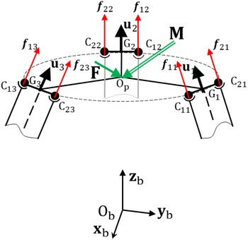
For the DELTA manipulator, the goal is to determine the forces and moments transmitted by the joints of the three legs. This model will be used for computing the orientation error of the manipulator caused by the clearance in the passive joints.
Let
 $\unicode{x1D6D5}$
ext = [F M]T be the external wrenches applied to the reference point of the platform Op (Fig. 3). The forces transmitted by the spherical joints centered at C1i and C2i in the i-th leg can be written, respectively, as
 \begin{equation}{\unicode{x1D6D5} }_{1\mathrm{i}}=\left[\begin{array}{c} \mathrm{f}_{1\mathrm{i}}\,{.}\,\mathbf{u}_{\mathrm{i}}\\ \\[-9pt] \mathbf{0} \end{array}\right];\quad {\unicode{x1D6D5} }_{2\mathrm{i}}=\left[\begin{array}{c} \mathrm{f}_{2\mathrm{i}}\,{.}\,\mathbf{u}_{\mathrm{i}}\\ \\[-9pt] \mathbf{0} \end{array}\right]\end{equation}
where u i is the unit vector of the direction of the bars (3). The analytic expression of vector u i is given as
 \begin{equation}\mathbf{u}_{\mathrm{i}}=\left[\begin{array}{c} \cos \unicode{x03B1} _{\mathrm{i}}.\cos \unicode{x03C6} _{2\mathrm{i}}.\sin \unicode{x03C6} _{3\mathrm{i}}+\sin \unicode{x03B1} _{\mathrm{i}}.\sin \unicode{x03C6} _{2\mathrm{i}}\\ \\[-9pt] \sin \unicode{x03B1} _{\mathrm{i}}.\sin \unicode{x03C6} _{3\mathrm{i}}.\cos \unicode{x03C6} _{2\mathrm{i}}+\cos \unicode{x03B1} _{\mathrm{i}}.\sin \unicode{x03C6} _{2\mathrm{i}}\\ \\[-9pt] \cos \unicode{x03C6} _{3\mathrm{i}}.\cos \unicode{x03C6} _{2\mathrm{i}} \end{array}\right]\end{equation}
Forces and moments applied on the moving platform.

According to the equilibrium of the platform (4), one can obtain
 \begin{align}\begin{cases} {\sum }_{\mathrm{i}=1}^{3}\!\left(\mathrm{f}_{1\mathrm{i}}+\mathrm{f}_{2\mathrm{i}}\right).\ \mathbf{u}_{\mathrm{i}}-\mathbf{F}=\mathbf{0}\\ \\[-8pt] {\sum }_{\mathrm{i}=1}^{3}\!\left(\mathrm{f}_{1\mathrm{i}}.\mathbf{v}_{1\mathrm{i}}\times \mathbf{u}_{\mathrm{i}}+\mathrm{f}_{2\mathrm{i}}.\mathbf{v}_{2\mathrm{i}}\times \mathbf{u}_{\mathrm{i}}\right)-\mathbf{M}=\mathbf{0} \end{cases}\end{align}
Where the analytic expression of the vectors v 1i and v 2i are given as
 \begin{equation}\mathbf{v}_{1\mathrm{i}}=\mathbf{O}_{\mathbf{p}}\mathbf{C}_{1\mathrm{i}}=\left[\begin{array}{c} \mathrm{r}_{\mathrm{p}}.\cos \unicode{x03B1} _{\mathrm{i}}-\dfrac{\mathrm{a}}{2}\sin \unicode{x03B1} _{\mathrm{i}}\\ \\[-7pt] \mathrm{r}_{\mathrm{p}}.\sin \unicode{x03B1} _{\mathrm{i}}+\dfrac{\mathrm{a}}{2}\cos \unicode{x03B1} _{\mathrm{i}}\\ \\[-7pt] 0 \end{array}\right];\quad \mathbf{v}_{2\mathrm{i}}=\mathbf{O}_{\mathbf{p}}\mathbf{C}_{2\mathrm{i}}=\left[\begin{array}{c} \mathrm{r}_{\mathrm{p}}.\cos \unicode{x03B1} _{\mathrm{i}}+\dfrac{\mathrm{a}}{2}\sin \unicode{x03B1} _{\mathrm{i}}\\ \\[-7pt] \mathrm{r}_{\mathrm{p}}.\sin \unicode{x03B1} _{\mathrm{i}}-\dfrac{\mathrm{a}}{2}\cos \unicode{x03B1} _{\mathrm{i}}\\ \\[-7pt] 0 \end{array}\right]\end{equation}
The system of Eq. (14) can be written in matrix form:
 \begin{equation}\left[\begin{array}{c@{\quad}c} \mathbf{A} & \mathbf{A}\\ \\[-9pt] \mathbf{B} & \mathbf{C} \end{array}\right]\left[\begin{array}{c@{\quad}c@{\quad}c@{\quad}c@{\quad}c@{\quad}c} \mathrm{f}_{11} & \mathrm{f}_{12} & \mathrm{f}_{13} & \mathrm{f}_{21} & \mathrm{f}_{22} & \mathrm{f}_{23} \end{array}\right]^{\mathrm{T}}=\left[\begin{array}{c} \mathbf{F}\\ \\[-9pt] \mathbf{M} \end{array}\right]\end{equation}
Where the expression of the matrices A, B and C are given as follows:
 \begin{equation}\mathbf{A}=\left[\begin{array}{c@{\quad}c@{\quad}c} \mathbf{u}_{1} & \mathbf{u}_{2} & \mathbf{u}_{3} \end{array}\right]\end{equation}
 \begin{equation}\mathbf{B}=\left[\begin{array}{c@{\quad}c@{\quad}c} \mathbf{v}_{\mathbf{11}}\times \mathbf{u}_{\mathbf{1}} & \mathbf{v}_{\mathbf{12}}\times \mathbf{u}_{\mathbf{2}} & \mathbf{v}_{\mathbf{13}}\times \mathbf{u}_{\mathbf{3}} \end{array}\right]\end{equation}
 \begin{equation}\mathbf{C}=\left[\begin{array}{c@{\quad}c@{\quad}c} \mathbf{v}_{\mathbf{21}}\times \mathbf{u}_{\mathbf{1}} & \mathbf{v}_{\mathbf{22}}\times \mathbf{u}_{\mathbf{2}} & \mathbf{v}_{\mathbf{23}}\times \mathbf{u}_{\mathbf{3}} \end{array}\right]\end{equation}
Thus, the forces transmitted by the spherical joint connected to the platform are computed (the matrices A and C-B must be non-singular):
 \begin{equation}\left[\begin{array}{c} \mathbf{f}_{\mathbf{11}}\\ \\[-9pt]\mathbf{f}_{\mathbf{12}}\\ \\[-9pt]\mathbf{f}_{\mathbf{13}}\\ \\[-9pt]\mathbf{f}_{\mathbf{21}}\\ \\[-9pt]\mathbf{f}_{\mathbf{22}}\\ \\[-9pt]\mathbf{f}_{\mathbf{23}} \end{array}\right]=\left[\begin{array}{c@{\quad}c} \mathbf{A}^{-\mathbf{1}}+\left(\mathbf{C}-\mathbf{B}\right)^{-\mathbf{1}}\mathbf{B}\mathbf{A}^{-\mathbf{1}} & -\left(\mathbf{C}-\mathbf{B}\right)^{-\mathbf{1}}\\ \\[-9pt]-\left(\mathbf{C}-\mathbf{B}\right)^{-\mathbf{1}}\mathbf{B}\mathbf{A}^{-\mathbf{1}} & \left(\mathbf{C}-\mathbf{B}\right)^{-\mathbf{1}} \end{array}\right]\left[\begin{array}{c} \mathbf{F}\\ \\[-9pt] \mathbf{M} \end{array}\right]\end{equation}
The expressions of the forces transmitted by the i-th leg are
 \begin{equation}\mathbf{f}_{\mathbf{1}\mathbf{i}}=\left[\mathbf{L}_{\mathbf{i}}\right]\left[\begin{array}{c} \mathbf{F}\\ \\[-9pt] \mathbf{M} \end{array}\right];\quad \mathbf{f}_{\mathbf{2}\mathbf{i}}=\left[\mathbf{L}_{\mathbf{i}+\mathbf{3}}\right]\left[\begin{array}{c} \mathbf{F}\\ \\[-9pt] \mathbf{M} \end{array}\right]\end{equation}
Where Li and Li + 3 are, respectively, the i-th and (i + 3)-th line vectors (1
 $\,{\times}\,$
6) from the matrix (6
 $\,{\times}\,$
6) defined in Eq. (20).
According to the Eqs. (12, 21), the forces transmitted by the spherical joint centered at C1i and C2i are given by
 \begin{equation}{\unicode{x1D6D5} }_{1\mathrm{i}}=\mathbf{H}_{1\mathrm{i}}\left[\begin{array}{c} \mathbf{F}\\ \\[-9pt] \mathbf{M} \end{array}\right];\quad {\unicode{x1D6D5} }_{2\mathrm{i}}=\mathbf{H}_{2\mathrm{i}}\left[\begin{array}{c} \mathbf{F}\\ \\[-9pt] \mathbf{M} \end{array}\right]\end{equation}
Where
 \begin{equation}\mathbf{H}_{1\mathrm{i}}=\left[\begin{array}{c@{\quad}c} \mathbf{u}_{\mathrm{i}} & \mathbf{0}\\ \\[-9pt] \mathbf{0} & \mathbf{0} \end{array}\right]\left[\begin{array}{c} \mathbf{L}_{\mathrm{i}}\\ \\[-9pt] \mathbf{0} \end{array}\right];\quad \mathbf{H}_{2\mathrm{i}}=\left[\begin{array}{c@{\quad}c} \mathbf{u}_{\mathrm{i}} & \mathbf{0}\\ \\[-9pt] \mathbf{0} & \mathbf{0} \end{array}\right]\left[\begin{array}{c} \mathbf{L}_{\mathrm{i}+3}\\ \\[-9pt] \mathbf{0} \end{array}\right]\end{equation}
According to the equilibrium of bars (3) and (3
 $^{\prime}$
), the forces transmitted by the spherical joint centered at C3i and C4i are given, respectively, as
 \begin{equation}{\unicode{x1D6D5} }_{3\mathrm{i}}=-{\unicode{x1D6D5} }_{1\mathrm{i}};\quad {\unicode{x1D6D5} }_{4\mathrm{i}}=-{\unicode{x1D6D5} }_{2\mathrm{i}}\end{equation}
3.2. Static model of RAF manipulator
For the RAF manipulator, the static model is already developed ([Reference Chouaibi, Chebbi, Affi and Romdhane11, Reference Affi and Romdhane29] present more details).
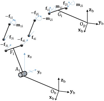
If a
 $\unicode{x1D6D5}$
ext = [F M]T is applied to Op, the forces will be transmitted by the SPS legs and the moments will be supported by the PKL legs (Fig. 4).
Forces and moments transmitted by the joints of the PKL legs.

The expression of the moments applied to the platform of the manipulator in the reference system fixed to the base can be written as
 \begin{equation}\mathbf{M}={\left[\begin{array}{c@{\quad}c@{\quad}c} \mathrm{L}_{\mathrm{p}} & \mathrm{M}_{\mathrm{p}} & \mathrm{N}_{\mathrm{p}} \end{array}\right]}_{\mathrm{S}_{\mathrm{b}}}^{\mathrm{T}}\end{equation}
According to the geometric model of both PKLs, the reaction forces and moments transmitted by the revolute joints D1i and D2i with axes
 $\mathbf{x}_{\mathrm{i}3}$
expressed in the reference system
 $\mathrm{S}_{3\mathrm{i}}$
can be written, respectively, by
 \begin{equation} {\unicode{x1D6D5} }_{\mathbf{1}\mathbf{i}}=\left[\begin{array}{c} \mathbf{f}_{\mathbf{1}\mathbf{i}}\\ \mathbf{m}_{\mathbf{1}\mathbf{i}} \end{array}\right];\quad {\unicode{x1D6D5} }_{\mathbf{2}\mathbf{i}}=\left[\begin{array}{c} \mathbf{f}_{\mathbf{2}\mathbf{i}}\\ \\[-8pt] \mathbf{m}_{\mathbf{2}\mathbf{i}} \end{array}\right]\end{equation}
The reaction forces transmitted by the spherical joints centered at points C3i and C4i expressed in the reference system
 $\mathrm{S}_{3\mathrm{i}}$
can be written, respectively, as
 \begin{equation}{\unicode{x1D6D5} }_{\mathbf{3}\mathbf{i}}=\left[\begin{array}{c} \mathbf{f}_{\mathbf{3}\mathbf{i}}\\ \mathbf{0} \end{array}\right];\quad {\unicode{x1D6D5} }_{\mathbf{4}\mathbf{i}}=\left[\begin{array}{c} \mathbf{f}_{\mathbf{4}\mathbf{i}}\\ \mathbf{0} \end{array}\right]\end{equation}
The equilibrium of the body (5), bars (3) and (3′) are, respectively, given by the following set of equations:
 \begin{align}\begin{cases} {\sum }_{\mathbf{j}=\mathbf{1}}^{\mathbf{2}}\,\mathbf{f}_{\mathbf{ji}}=\mathbf{0}\\ \\[-9pt]\mathbf{f}_{\mathbf{1}\mathbf{i}}-\mathbf{f}_{\mathbf{3}\mathbf{i}}=\mathbf{0}\\ \\[-9pt]\begin{array}{l} \mathbf{f}_{\mathbf{2}\mathbf{i}}-\mathbf{f}_{\mathbf{4}\mathbf{i}}=\mathbf{0}\\ \\[-9pt]{\sum }_{\mathbf{j}=\mathbf{1}}^{\mathbf{2}}\mathbf{m}_{\mathbf{ji}}+\mathbf{f}_{\mathbf{1}\mathbf{i}}\times \mathbf{D}_{\mathbf{1}\mathbf{i}} \mathbf{D}_{\mathbf{2}\mathbf{i}}=\left[\begin{array}{c} \mathrm{L}_{\mathrm{i}}\quad 0\quad \mathrm{N}_{\mathrm{i}} \end{array}\right]^{\mathbf{T}}\\ \\[-9pt]\begin{array}{l} \mathbf{m}_{\mathbf{1}\mathbf{i}}+\mathbf{f}_{\mathbf{1}\mathbf{i}}\times \mathbf{D}_{\mathbf{1}\mathbf{i}}\mathbf{C}_{\mathbf{3}\mathbf{i}}=\mathbf{0}\\ \\[-9pt]\mathbf{m}_{\mathbf{2}\mathbf{i}}+\mathbf{f}_{\mathbf{2}\mathbf{i}}\times \mathbf{D}_{\mathbf{2}\mathbf{i}}\mathbf{C}_{\mathbf{4}\mathbf{i}}=\mathbf{0} \end{array} \end{array} \end{cases}\end{align}
By solving the system of Eqs. (28), the forces and the moments transmitted by the joints expressed in the reference system S3i are given as
 \begin{equation}\mathbf{f}_{\mathbf{1}\mathbf{i}}=\mathbf{f}_{\mathbf{3}\mathbf{i}}=-\mathbf{f}_{\mathbf{2}\mathbf{i}}=-\mathbf{f}_{\mathbf{4}\mathbf{i}}={\left[\begin{array}{c@{\quad}c@{\quad}c} \dfrac{\mathrm{N}_{\mathrm{i}}}{\mathrm{a}} & -\dfrac{\mathrm{L}_{\mathrm{i}}}{\mathrm{a}}\tan \unicode{x03C6} _{2\mathrm{i}} & -\dfrac{\mathrm{L}_{\mathrm{i}}}{\mathrm{a}} \end{array}\right]}_{\mathbf{S}_{\mathbf{3}\mathbf{i}}}^{\mathbf{T}}\end{equation}
 \begin{equation}\mathbf{m}_{\mathbf{1}\mathbf{i}}=-\mathbf{m}_{\mathbf{2}\mathbf{i}}={\left[\begin{array}{c@{\quad}c@{\quad}c} 0 & -\dfrac{\mathrm{N}_{\mathrm{i}}}{\mathrm{a}}.\mathrm{l}_{3}.\mathrm{c}\unicode{x03C6} _{2\mathrm{i}} & \dfrac{\mathrm{N}_{\mathrm{i}}}{\mathrm{a}}.\mathrm{l}_{3}.\mathrm{s}\unicode{x03C6} _{2\mathrm{i}} \end{array}\right]}_{\mathbf{S}_{\mathbf{31}}}^{\mathbf{T}}\end{equation}
According to the equilibrium of the link (2), the reaction forces and moments transmitted by this revolute joint expressed in the reference system S3i can be determined:
 \begin{align}\begin{cases} \mathbf{f}_{{\mathbf{A}_{\mathbf{i}}}}=\mathbf{0}\\ \\[-9pt] \mathbf{m}_{{\mathbf{A}_{\mathbf{i}}}}=\left[\begin{array}{c@{\quad}c@{\quad}c} \mathrm{L}_{\mathrm{i}} & 0 & \mathrm{N}_{\mathrm{i}} \end{array}\right]^{\mathbf{T}} \end{cases} \end{align}
Li and Ni moments of the first PKL are given by
 \begin{align}\begin{cases} \mathrm{L}_{\mathrm{i}}=\left(\mathrm{L}_{\mathrm{p}}\mathrm{c}\unicode{x03B1} _{\mathrm{i}}+\mathrm{M}_{\mathrm{p}}\mathrm{s}\unicode{x03B1} _{\mathrm{i}}\right).\mathrm{c}\unicode{x03C6} _{3\mathrm{i}}\\ \\[-9pt] \mathrm{N}_{\mathrm{i}}=\left(\mathrm{L}_{\mathrm{p}}\mathrm{c}\unicode{x03B1} _{\mathrm{i}}+\mathrm{M}_{\mathrm{p}}\mathrm{s}\unicode{x03B1} _{\mathrm{i}}\right).\mathrm{s}\unicode{x03C6} _{3\mathrm{i}} \end{cases}\end{align}
Li and Ni moments of the second PKL are given by
 \begin{align}\begin{cases} \mathrm{L}_{\mathrm{i}}=\left(\mathrm{L}_{\mathrm{p}}\mathrm{c}\unicode{x03B1} _{\mathrm{i}}+\mathrm{M}_{\mathrm{p}}\mathrm{s}\unicode{x03B1} _{\mathrm{i}}\right).\mathrm{c}\unicode{x03C6} _{3\mathrm{i}}-\mathrm{N}_{\mathrm{p}}\mathrm{s}\unicode{x03C6} _{3\mathrm{i}}\\ \\[-9pt] \mathrm{N}_{\mathrm{i}}=\left(\mathrm{L}_{\mathrm{p}}\mathrm{c}\unicode{x03B1} _{\mathrm{i}}+\mathrm{M}_{\mathrm{p}}\mathrm{s}\unicode{x03B1} _{\mathrm{i}}\right).\mathrm{s}\unicode{x03C6} _{3\mathrm{i}}+\mathrm{N}_{\mathrm{p}}\mathrm{c}\unicode{x03C6} _{3\mathrm{i}} \end{cases}\end{align}
4. Orientation error of the translational parallel manipulator
In this section, an analytical model that determines the orientation error of the translational parallel manipulator due to the clearance in the passive joints, is demonstrated. The orientation error of the RAF manipulator was presented by ref. [Reference Chouaibi, Chebbi, Affi and Romdhane11].
The orientation error is a function of the nominal pose, the external wrenches applied to the platform, the clearance magnitude and the structural parameters.
The local pose error
 $\boldsymbol{\Delta}\unicode{x1D6C5}$
ji caused by the clearance in the j-th passive spherical joint in the i-th leg is determined by using the model given by ref. [Reference Chouaibi, Chebbi, Affi and Romdhane11]:
 \begin{equation}{\boldsymbol\Delta }{\unicode{x1D6C5} }_{\mathrm{ji}}=\frac{{\unicode{x1D6D5} }_{\mathrm{ji}}}{\left|\left|{\unicode{x1D6D5} }_{\mathrm{ji}}\right|\right|}.\unicode{x025B} _{\mathrm{ji}}=\frac{\mathbf{H}_{\mathrm{ji}}.{\unicode{x1D6D5} }_{\mathrm{ext}}}{\left|\left|\mathbf{H}_{\mathrm{ji}}.{\unicode{x1D6D5} }_{\mathrm{ext}}\right|\right|}.\unicode{x025B} _{\mathrm{ji}}\end{equation}
The local pose error
 $\boldsymbol{\Delta}\unicode{x1D6C5}$
ji caused by axial and radial clearance in the j-th revolute joint in the i-th leg is calculated by the model given by ref. [Reference Chouaibi, Chebbi, Affi and Romdhane11]:
 \begin{equation}{\boldsymbol\Delta }\unicode{x1D6C5}_{\mathbf{ji}}=\left({\mathbf{W}}_{\mathbf{1},\mathbf{ji}}^{\mathbf{T}}\frac{\mathbf{W}_{\mathbf{1},\mathbf{ji}}\mathbf{H}_{\mathbf{ji}}{\unicode{x1D6D5} }_{\mathbf{ext}}}{\left|\left|\mathbf{W}_{\mathbf{1},\mathbf{ji}}\mathbf{H}_{\mathbf{ji}}{\unicode{x1D6D5} }_{\mathbf{ext}}\right|\right|}+{\mathbf{W}}_{\mathbf{2},\mathbf{ji}}^{\mathbf{T}}\frac{\mathbf{W}_{\mathbf{2},\mathbf{ji}}\mathbf{H}_{\mathbf{ji}}{\unicode{x1D6D5} }_{\mathbf{ext}}}{\left|\left|\mathbf{W}_{\mathbf{2},\mathbf{ji}}\mathbf{H}_{\mathbf{ji}}{\unicode{x1D6D5} }_{\mathbf{ext}}\right|\right|}\right).{\unicode{x1D6C6} }_{\mathbf{dji}}+{\mathbf{W}}_{\mathbf{3},\mathbf{ji}}^{\mathbf{T}}\frac{\mathbf{W}_{\mathbf{3},\mathbf{ji}}\mathbf{H}_{\mathbf{ji}}{\unicode{x1D6D5} }_{\mathbf{ext}}}{\left|\left|\mathbf{W}_{\mathbf{3},\mathbf{ji}}\mathbf{H}_{\mathbf{ji}}{\unicode{x1D6D5} }_{\mathbf{ext}}\right|\right|}.{\unicode{x1D6C6} }_{\mathbf{aji}}\end{equation}
Where H
ij is a (6 × 6) matrix that relates the vector forces and moments transmitted by the j-th joint of the i-th leg (
 ${\unicode{x1D6D5} }_{\mathrm{ji}}$
) to the external wrench applied on the platform (
 ${\unicode{x1D6D5} }_{\mathrm{ext}}$
) expressed by the following equation:
 \begin{equation}{\unicode{x1D6D5} }_{\mathbf{ji}}=\mathbf{H}_{\mathbf{ji}}.{\unicode{x1D6D5} }_{\mathbf{ext}}\end{equation}
W 1,ji and W 2,ji are 3 × 6 matrices and W 3,ji is a vector of six components, which depends on the architecture and the configuration of the manipulator.
By applying the virtual work principle [Reference Chebbi, Affi and Romdhane2, Reference Parenti-Castelli and Venanzi10, Reference Chouaibi, Chebbi, Affi and Romdhane11], we get
 \begin{equation}{\unicode{x1D6D5} }_{\mathbf{ext}}^{\mathbf{T}}.\boldsymbol\Delta \boldsymbol\Gamma _{\mathbf{ij}}+{\unicode{x1D6D5} }_{\mathbf{ij}}^{\mathbf{T}}.\boldsymbol\Delta \unicode{x1D6C5} _{\mathbf{ij}}=0\end{equation}
Where
 $\boldsymbol{\Delta\Gamma}$
ji corresponds to the pose error of the platform.
Substituting
 ${\unicode{x1D6D5} }_{\mathrm{ji}}$
by its expression Eq. (36), we obtained
 \begin{equation}{\boldsymbol\Delta }{\boldsymbol\Gamma }_{\mathbf{ji}}=-{\mathbf{H}}_{\mathbf{ji}}^{\mathbf{T}}.{\boldsymbol\Delta }{\unicode{x1D6C5} }_{\mathbf{ji}}\end{equation}
Thus, the platform pose error that is due to the clearance in all the joints is given by [Reference Binaud, Caro and Wenger15–Reference Wu, Li, Wang and Wang17]
 \begin{equation}{\boldsymbol\Delta \Gamma }=-\sum\nolimits_{i}\sum\nolimits_{j}{\mathbf{H}}_{\mathbf{ji}}^{\mathbf{T}}.{\boldsymbol\Delta }{\unicode{x1D6C5} }_{\mathbf{ji}}\end{equation}
 ${\boldsymbol{\Delta \Gamma} }$
is a vector (6 × 1). The first three components representing the position errors and the last three components correspond to the orientation errors of the manipulator around the x-, y- and z-axes, respectively.
5. Proposed indices
This part is devoted to dealing with two indices, which are proposed in order to compare 3-DOF TPMs on maximum orientation error and their sensitivity to the geometric parameters and joint clearances.
5.1. Maximum orientation error
According to Eq. (39), the analytic expression of orientation error caused by the clearance in passive joints for a given external wrench applied to the reference point Op of the platform can be written as
 \begin{equation}\boldsymbol\Gamma_{\mathrm{k}}=\mathrm{h}(\mathrm{x}) \end{equation}
where
 $\boldsymbol{\Gamma}$
k (
 $\mathrm{k}=4,5,6$
) represents the k-th component of the vector
 $\boldsymbol{\Delta\Gamma}$
.
x is the vector (6 ×1) of variables which represents the external wrench applied on the reference point Op of the platform
 $\unicode{x1D6D5}$
ext.
The index intended is to find the maximum orientation error of the manipulator in each position of the workspace without depending on the direction of
 $\unicode{x1D6D5}$
ext.
The maximum orientation error corresponds to the optimization of the objective function defined by
 \begin{align}\begin{cases} \max \left(\mathrm{h}\!\left(\mathbf{x}\right)\right)\\ \\[-9pt] \mathbf{l}_{\mathrm{b}}\leq \mathbf{x}\leq \mathbf{u}_{\mathrm{b}} \end{cases}\end{align}
Where l
b and u
b correspond to the vectors of the lower and the upper bounds of the variables, respectively. Since the orientation error of the platform depends on the direction of the external wrench
 $\unicode{x1D6D5}$
ext and does not depend on its magnitude [Reference Chebbi, Affi and Romdhane2, Reference Chouaibi, Chebbi, Affi and Romdhane11]. The magnitude of the external wrench does not affect the orientation of the platform when considering the clearance in the joints. However, the direction of the external wrench can affect this orientation. Therefore, by selecting all possible values for the six components, from {–1, 0, 1} of the external wrench one can cover all its possible directions (36 = 729). Then, the vectors l
b and u
b are defined as follows:
 \begin{equation}\mathbf{u}_{\mathrm{b}}=-\mathbf{l}_{\mathrm{b}}=\left[\begin{array}{c@{\quad}c@{\quad}c@{\quad}c@{\quad}c@{\quad}c} 1 & 1 & 1 & 1 & 1 & 1 \end{array}\right]^{\mathrm{T}}\end{equation}
Using the value of the vectors u
b and l
b and taking an arbitrary initial guess, x
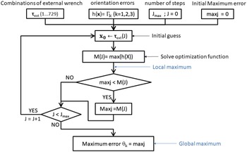
0, of the vector of variable x, the problem defined by Eq. (41) can be solved. But the obtained result represents a local maximum orientation error of the objective function h(x). One of the best alternatives to solve the problem is to consider a combination of external wrench applied to the platform
 $\unicode{x1D6D5}$
ext, as an initial guess. Thus, the maximum orientation error chosen corresponds to the maximum of all the local maxima of h(x). The maximum orientation error of the platform due to the clearance in passive joints which will be taken as index in order to compare TPMs. A flow chart of the calculation process is illustrated by Fig. 5.
Flow chart of the maximum orientation error.

The MATLAB Optimization Toolbox can be used to solve the problem defined by Eq. (41).
5.2. Condition index
In order to analyze the sensitivity of the orientation error of the manipulator to the geometric parameters variations and the clearance in the passive joints, a condition index is used [Reference Merlet31, Reference Gosselin and Angeles32]. The relationships between the variation of the orientation error and the variations of the geometric parameters and the joint clearance are given by
 \begin{equation}{\unicode{x1D6C5}{\unicode{x03B8}} }=\mathbf{J}_{1\mathrm{M}}.{\unicode{x1D6C5} }\mathbf{q}_{1}\end{equation}
 \begin{equation}{\unicode{x1D6C5}{ \unicode{x03B8}} }=\mathbf{J}_{\mathbf{2}\mathbf{M}}.{\unicode{x1D6C5} }\mathbf{q}_{\mathbf{2}}\end{equation}
Where
 $\unicode{x1D6C5}{\unicode{x03B8}}$
= [δ
 $\unicode{x03B8}$
1 δ
 $\unicode{x03B8}$
2 δ
 $\unicode{x03B8}$
3]T corresponds to the vector of the orientation errors variation of the manipulator.
J 1M and J 2M are a (3 ×np) matrices. Where np is the number of geometric parameters and joint clearances.
δq 1 and δq 2 stand for the vectors of the variations in geometric parameters and joint clearances, respectively.
The condition number of the geometric parameters and joint clearances are defined as follows:
 \begin{equation}\mathbf{k}_{\mathbf{p}}\!\left(\mathbf{J}_{\mathbf{1}\mathbf{M}}\right)=\left|\left|\mathbf{J}_{\mathbf{1}\mathbf{M}}\right|\right|.\left|\left|{\mathbf{J}}_{\mathbf{1}\mathbf{M}}^{-\mathbf{1}}\right|\right|\end{equation}
 \begin{equation}\mathbf{k}_{\mathbf{j}}\!\left(\mathbf{J}_{\mathbf{2}\mathbf{M}}\right)=\left|\left|\mathbf{J}_{\mathbf{2}\mathbf{M}}\right|\right|.\left|\left|{\mathbf{J}}_{\mathbf{2}\mathbf{M}}^{-\mathbf{1}}\right|\right|\end{equation}
kp and kj characterize the sensitivity of the orientation error of the manipulator to variations in the geometric parameters and the joint clearances.
The condition number that expresses how a relative variation in q (geometric parameters and joint clearances) gets multiplied and leads to a relative variation in
 $\unicode{x03B8}$
(orientation error) will be used as a performance index.
The condition number ranges from 1 to infinity. For more practical representation, the 1/k (0 ≤ (1/k) ≤ 1), referred to the inverse condition index, is used. When the value of (1/k) is close to 1 it indicates that the matrix is less sensitive, if it is small that means the sensitivity of the matrix to the parameters is important. The value of (1/k) is equal to zero, corresponds to a singular Jacobian matrix J. To give a physical meaning to the condition number, we have analyzed the limit values. It is apparent that the robot which has limit values close to 1 is the least sensitive.
For the RAF, the expression of the q 1(1 ×12) and q 2(1 ×22) vectors is, respectively, given by
 \begin{equation}{\unicode{x1D6C5} }\mathbf{q}_{\mathbf{1}}=\left[\begin{array}{c@{\quad}c} {{\unicode{x1D6C5} }\mathbf{q}_{\mathbf{1}}}_{\mathbf{1}} & {{\unicode{x1D6C5} }\mathbf{q}_{\mathbf{1}}}_{\mathbf{2}} \end{array}\right]^{\mathrm{T}}\end{equation}
 \begin{equation}{{\unicode{x1D6C5} }\mathbf{q}_{\mathbf{1}}}_{i}=\left[\begin{array}{c@{\quad}c} \begin{array}{c@{\quad}c@{\quad}c@{}} \unicode{x03B4} \mathrm{l}_{2\mathrm{i}} & \unicode{x03B4} \mathrm{l}_{3\mathrm{i}} & \unicode{x03B4} \mathrm{a}_{\mathrm{i}} \end{array} & \begin{array}{c@{\quad}c@{\quad}c} \unicode{x03B4} \unicode{x03BB} _{\mathrm{i}} & \unicode{x03B4} {\mathrm{r}_{\mathrm{b}}}_{\mathrm{i}} & \unicode{x03B4} {\mathrm{r}_{\mathrm{p}}}_{\mathrm{i}} \end{array} \end{array}\right]^{\mathrm{T}}\end{equation}
Where
 $\unicode{x03B4} \mathrm{l}_{2\mathrm{i}}$
,
 $\unicode{x03B4} \mathrm{l}_{3\mathrm{i}}$
,
 $\unicode{x03B4} \mathrm{a}_{\mathrm{i}}$
,
 $\unicode{x03B4} \unicode{x03BB} _{\mathrm{i}}$
,
 $\unicode{x03B4} {\mathrm{r}_{\mathrm{b}}}_{\mathrm{i}}$
and
 $\unicode{x03B4} {\mathrm{r}_{\mathrm{p}}}_{\mathrm{i}}$
describe the variations in the geometric parameters
 $\mathrm{l}_{2\mathrm{i}}$
,
 $\mathrm{l}_{3\mathrm{i}}$
,
 $\mathrm{a}_{\mathrm{i}}$
,
 $\unicode{x03BB} _{\mathrm{i}}$
,
 ${\mathrm{r}_{\mathrm{b}}}_{\mathrm{i}}$
and
 ${\mathrm{r}_{\mathrm{p}}}_{\mathrm{i}}$
, respectively, of the i-th leg.
 \begin{equation}{\unicode{x1D6C5} }\mathbf{q}_{\mathbf{2}}=\left[\begin{array}{@{}c@{\quad}c@{}} {{\unicode{x1D6C5} }\mathbf{q}_{\mathbf{2}}}_{\mathbf{1}} & {{\unicode{x1D6C5} }\mathbf{q}_{\mathbf{2}}}_{\mathbf{2}} \end{array}\right]^{\mathrm{T}}\end{equation}
 \begin{equation}{\unicode{x1D6C5} }{\mathbf{q}_{\mathbf{2}}}_{\mathbf{1}}=\left[\begin{array}{@{}c@{\quad}c@{\quad}c@{\quad}c@{\quad}c@{\quad}c@{\quad}c@{}} \unicode{x03B4} \mathbf{E}_{\mathrm{G}\mathrm{'}11} & \unicode{x03B4} \mathbf{E}_{\mathrm{G}11} & \unicode{x03B4} \mathbf{E}_{\mathrm{D}11} & \unicode{x03B4} \mathbf{E}_{\mathrm{D}21} & \unicode{x03B4} \mathrm{E}_{\mathrm{C}31} & \unicode{x03B4} \mathrm{E}_{\mathrm{C}41} & \unicode{x03B4} \mathbf{E}_{\mathrm{A}11} \end{array}\right]^{\mathrm{T}}\end{equation}
 \begin{equation}{\unicode{x1D6C5} }{\mathbf{q}_{\mathbf{2}}}_{\mathbf{2}}=\left[\begin{array}{@{}c@{\quad}c} \begin{array}{c@{\quad}c@{}} \unicode{x03B4} \mathbf{E}_{\mathrm{G}12} & \begin{array}{c@{\quad}c} \unicode{x03B4} \mathbf{E}_{\mathrm{D}12} & \unicode{x03B4} \mathbf{E}_{\mathrm{D}22} \end{array} \end{array} & \begin{array}{c@{\quad}c@{\quad}c@{}} \unicode{x03B4} \mathrm{E}_{\mathrm{C}32} & \unicode{x03B4} \mathrm{E}_{\mathrm{C}42} & \unicode{x03B4} \mathbf{E}_{\mathrm{A}12} \end{array} \end{array}\right]^{\mathrm{T}}\end{equation}
Where
 $\unicode{x03B4} \mathbf{E}_{\mathrm{G}\mathrm{'}11}=\unicode{x03B4} \mathbf{E}_{\mathrm{G}1\mathrm{i}}=\unicode{x03B4} \mathbf{E}_{\mathrm{A}1\mathrm{i}}=\unicode{x03B4} \mathbf{E}_{\mathrm{D}1\mathrm{i}}=\unicode{x03B4} \mathbf{E}_{\mathrm{D}2\mathrm{i}}=\left[\begin{array}{@{}c@{\quad}c@{}} \unicode{x03B4} \unicode{x025B} _{\mathrm{dji}} & \unicode{x03B4} \unicode{x025B} _{\mathrm{aji}} \end{array}\right]^{\mathrm{T}}$
describes the variations in the radial and axial clearances, respectively, in each j-th revolute joint of the i-th leg.
 $\unicode{x03B4} \mathrm{E}_{\mathrm{Cji}}=\unicode{x03B4} \unicode{x025B} _{\mathrm{ji}}$
describe the variations in the clearance of j-th spherical joint of the i-th leg.
The expression of the J 1M (3 ×12) and J 2M (3 ×22) matrices becomes
 \begin{equation}\mathbf{J}_{\mathbf{M}\mathbf{1}}=\left(\begin{array}{c@{\quad}c@{\quad}c} \begin{array}{c@{\quad}c@{\quad}c} \dfrac{\partial {\unicode{x1D6C9} }_{\mathbf{1}}}{\partial \mathbf{l}_{\mathbf{21}}} & \ldots & \dfrac{\partial {\unicode{x1D6C9} }_{\mathbf{1}}}{\partial {\mathbf{r}_{\mathbf{p}}}_{\mathbf{1}}}\\ \\[-7pt] \dfrac{\partial {\unicode{x1D6C9} }_{\mathbf{2}}}{\partial \mathbf{l}_{\mathbf{21}}} & \ldots & \dfrac{\partial {\unicode{x1D6C9} }_{\mathbf{2}}}{\partial {\mathbf{r}_{\mathbf{p}}}_{\mathbf{1}}}\\ \\[-7pt] \dfrac{\partial {\unicode{x1D6C9} }_{\mathbf{3}}}{\partial \mathbf{l}_{\mathbf{21}}} & \ldots & \dfrac{\partial {\unicode{x1D6C9} }_{\mathbf{3}}}{\partial {\mathbf{r}_{\mathbf{p}}}_{\mathbf{1}}} \end{array} & & \begin{array}{c@{\quad}c@{\quad}c} \dfrac{\partial {\unicode{x1D6C9} }_{\mathbf{1}}}{\partial \mathbf{l}_{\mathbf{22}}} & \ldots & \dfrac{\partial {\unicode{x1D6C9} }_{\mathbf{1}}}{\partial {\mathbf{r}_{\mathbf{p}}}_{\mathbf{2}}}\\ \\[-7pt] \dfrac{\partial {\unicode{x1D6C9} }_{\mathbf{2}}}{\partial \mathbf{l}_{\mathbf{22}}} & \ldots & \dfrac{\partial {\unicode{x1D6C9} }_{\mathbf{2}}}{\partial {\mathbf{r}_{\mathbf{p}}}_{\mathbf{2}}}\\ \\[-7pt] \dfrac{\partial {\unicode{x1D6C9} }_{\mathbf{3}}}{\partial \mathbf{l}_{\mathbf{22}}} & \ldots & \dfrac{\partial {\unicode{x1D6C9} }_{\mathbf{3}}}{\partial {\mathbf{r}_{\mathbf{p}}}_{\mathbf{2}}} \end{array} \end{array}\right)\end{equation}
 \begin{equation}\mathbf{J}_{\mathbf{M}\mathbf{2}}=\left(\begin{array}{c@{\quad}c@{\quad}c} \dfrac{\partial {\unicode{x1D6C9} }_{\mathbf{1}}}{\partial {{\unicode{x1D6C6}}_{\mathbf{d}}}_{\mathbf{G'}\mathbf{11}}} & \dfrac{\partial {\unicode{x1D6C9} }_{\mathbf{1}}}{\partial {{\unicode{x1D6C6} }_{\mathbf{a}}}_{\mathbf{G'}\mathbf{11}}} & \dfrac{\partial {\unicode{x1D6C9} }_{\mathbf{1}}}{\partial {{\unicode{x1D6C6} }_{\mathbf{d}}}_{\mathbf{G}\mathbf{11}}}\\ \\[-7pt] \dfrac{\partial {\unicode{x1D6C9} }_{\mathbf{2}}}{\partial {{\unicode{x1D6C6} }_{\mathbf{d}}}_{\mathbf{G'}\mathbf{11}}} & \dfrac{\partial {\unicode{x1D6C9} }_{\mathbf{2}}}{\partial {{\unicode{x1D6C6} }_{\mathbf{a}}}_{\mathbf{G'}\mathbf{11}}} & \dfrac{\partial {\unicode{x1D6C9} }_{\mathbf{2}}}{\partial {{\unicode{x1D6C6} }_{\mathbf{d}}}_{\mathbf{G}\mathbf{11}}}\\ \\[-7pt] \dfrac{\partial {\unicode{x1D6C9} }_{\mathbf{3}}}{\partial {{\unicode{x1D6C6} }_{\mathbf{d}}}_{\mathbf{G'}\mathbf{11}}} & \dfrac{\partial {\unicode{x1D6C9} }_{\mathbf{3}}}{\partial {{\unicode{x1D6C6} }_{\mathbf{a}}}_{\mathbf{G'}\mathbf{11}}} & \dfrac{\partial {\unicode{x1D6C9} }_{\mathbf{3}}}{\partial {{\unicode{x1D6C6} }_{\mathbf{d}}}_{\mathbf{G}\mathbf{11}}} \end{array}\begin{array}{c@{\quad}c} \begin{array}{c} \begin{array}{c} \ldots \\ \\[-7pt] \end{array}\\ \\[-7pt] \begin{array}{c} \ldots \\ \\[-7pt] \end{array}\\ \\[-7pt] \ldots \end{array} & \begin{array}{c@{\quad}c@{\quad}c} \dfrac{\partial {\unicode{x1D6C9} }_{\mathbf{1}}}{\partial {\unicode{x1D6C6} }_{\mathbf{42}}} & \dfrac{\partial {\unicode{x1D6C9} }_{\mathbf{1}}}{\partial {{\unicode{x1D6C6} }_{\mathbf{d}}}_{\mathbf{A}\mathbf{12}}} & \dfrac{\partial {\unicode{x1D6C9} }_{\mathbf{1}}}{\partial {{\unicode{x1D6C6} }_{\mathbf{a}}}_{\mathbf{A}\mathbf{12}}}\\ \\[-7pt] \dfrac{\partial {\unicode{x1D6C9} }_{\mathbf{2}}}{\partial {\unicode{x1D6C6} }_{\mathbf{42}}} & \dfrac{\partial {\unicode{x1D6C9} }_{\mathbf{2}}}{\partial {{\unicode{x1D6C6} }_{\mathbf{d}}}_{\mathbf{A}\mathbf{12}}} & \dfrac{\partial {\unicode{x1D6C9} }_{\mathbf{2}}}{\partial {{\unicode{x1D6C6} }_{\mathbf{a}}}_{\mathbf{A}\mathbf{12}}}\\ \\[-7pt] \dfrac{\partial {\unicode{x1D6C9} }_{\mathbf{3}}}{\partial {\unicode{x1D6C6} }_{\mathbf{42}}} & \dfrac{\partial {\unicode{x1D6C9} }_{\mathbf{3}}}{\partial {{\unicode{x1D6C6} }_{\mathbf{d}}}_{\mathbf{A}\mathbf{12}}} & \dfrac{\partial {\unicode{x1D6C9} }_{\mathbf{3}}}{\partial {{\unicode{x1D6C6} }_{\mathbf{a}}}_{\mathbf{A}\mathbf{12}}} \end{array} \end{array}\right)\end{equation}
For the DELTA manipulator, the components of the geometric parameters vector q 1 and the joint clearances vector q 2 are, respectively, given by
 \begin{equation}{\unicode{x1D6C5} }\mathbf{q}_{\mathbf{1}}=\left[\begin{array}{c@{\quad}c@{\quad}c} {{\unicode{x1D6C5} }\mathbf{q}_{\mathbf{1}}}_{\mathbf{1}} & {{\unicode{x1D6C5} }\mathbf{q}_{\mathbf{1}}}_{\mathbf{2}} & {{\unicode{x1D6C5} }\mathbf{q}_{\mathbf{1}}}_{\mathbf{3}} \end{array}\right]^{\mathrm{T}}\end{equation}
 \begin{equation}{{\unicode{x1D6C5} }\mathbf{q}_{\mathbf{1}}}_{i}=\left[\begin{array}{@{}c@{\quad}c} \begin{array}{c@{\quad}c@{\quad}c@{}} \unicode{x03B4} \mathrm{l}_{2\mathrm{i}} & \unicode{x03B4} \mathrm{l}_{3\mathrm{i}} & \unicode{x03B4} \mathrm{a}_{\mathrm{i}} \end{array} & \begin{array}{c@{\quad}c@{}} \unicode{x03B4} {\mathrm{r}_{\mathrm{b}}}_{\mathrm{i}} & {\unicode{x03B4} \mathrm{r}_{\mathrm{p}}}_{\mathrm{i}} \end{array} \end{array}\right]\end{equation}
Where
 $\unicode{x03B4} \mathrm{l}_{2\mathrm{i}}$
,
 $\unicode{x03B4} \mathrm{l}_{3\mathrm{i}}$
,
 $\unicode{x03B4} \mathrm{a}_{\mathrm{i}}$
,
 $\unicode{x03B4} {\mathrm{r}_{\mathrm{b}}}_{\mathrm{i}}$
and
 $\unicode{x03B4} {\mathrm{r}_{\mathrm{p}}}_{\mathrm{i}}$
depicts the variations in the geometric parameters
 $\mathrm{l}_{2\mathrm{i}}$
,
 $\mathrm{l}_{3\mathrm{i}}$
,
 $\mathrm{a}_{\mathrm{i}}$
,
 ${\mathrm{r}_{\mathrm{b}}}_{\mathrm{i}}$
and
 ${\mathrm{r}_{\mathrm{p}}}_{\mathrm{i}}$
, respectively, of the i-th leg.
 \begin{equation}{\unicode{x1D6C5} }\mathbf{q}_{\mathbf{2}}=\left[\begin{array}{c@{\quad}c@{\quad}c} {{\unicode{x1D6C5} }\mathbf{q}_{\mathbf{2}}}_{\mathbf{1}} & {{\unicode{x1D6C5} }\mathbf{q}_{\mathbf{2}}}_{\mathbf{2}} & {{\unicode{x1D6C5} }\mathbf{q}_{\mathbf{2}}}_{\mathbf{3}} \end{array}\right]^{\mathrm{T}}\end{equation}
 \begin{equation}\boldsymbol{\unicode{x03B4} }{\mathbf{q}_{\mathbf{2}}}_{i}=\left[\begin{array}{c@{\quad}c} \begin{array}{c@{\quad}c} \unicode{x03B4} \unicode{x025B} _{1\mathrm{i}} & \unicode{x03B4} \unicode{x025B} _{2\mathrm{i}} \end{array} & \begin{array}{c@{\quad}c@{}} \unicode{x03B4} \unicode{x025B} _{3\mathrm{i}} & \unicode{x03B4} \unicode{x025B} _{4\mathrm{i}} \end{array} \end{array}\right]^{\mathrm{T}}\end{equation}
The expression of the J 1M (3 ×15) and J 2M (3 ×12) matrices becomes
 \begin{equation}\mathbf{J}_{\mathbf{M}\mathbf{1}}=\left(\begin{array}{c@{\quad}c@{\quad}c} \dfrac{\partial {\unicode{x1D6C9} }_{\mathbf{1}}}{\partial \mathbf{l}_{\mathbf{21}}} & \ldots & \dfrac{\partial {\unicode{x1D6C9} }_{\mathbf{1}}}{\partial {\mathbf{r}_{\mathbf{p}}}_{\mathbf{1}}}\\ \\[-9pt] \dfrac{\partial {\unicode{x1D6C9} }_{\mathbf{2}}}{\partial \mathbf{l}_{\mathbf{21}}} & \ldots & \dfrac{\partial {\unicode{x1D6C9} }_{\mathbf{2}}}{\partial {\mathbf{r}_{\mathbf{p}}}_{\mathbf{1}}}\\ \\[-9pt] \dfrac{\partial {\unicode{x1D6C9} }_{\mathbf{3}}}{\partial \mathbf{l}_{\mathbf{21}}} & \ldots & \dfrac{\partial {\unicode{x1D6C9} }_{\mathbf{3}}}{\partial {\mathbf{r}_{\mathbf{p}}}_{\mathbf{1}}} \end{array}\begin{array}{c@{\quad}c@{\quad}c} \dfrac{\partial {\unicode{x1D6C9} }_{\mathbf{1}}}{\partial \mathbf{l}_{\mathbf{22}}} & \ldots & \dfrac{\partial {\unicode{x1D6C9} }_{\mathbf{1}}}{\partial {\mathbf{r}_{\mathbf{p}}}_{\mathbf{2}}}\\ \\[-9pt] \dfrac{\partial {\unicode{x1D6C9} }_{\mathbf{2}}}{\partial \mathbf{l}_{\mathbf{22}}} & \ldots & \dfrac{\partial {\unicode{x1D6C9} }_{\mathbf{2}}}{\partial {\mathbf{r}_{\mathbf{p}}}_{\mathbf{2}}}\\ \\[-9pt] \dfrac{\partial {\unicode{x1D6C9} }_{\mathbf{3}}}{\partial \mathbf{l}_{\mathbf{22}}} & \ldots & \dfrac{\partial {\unicode{x1D6C9} }_{\mathbf{3}}}{\partial {\mathbf{r}_{\mathbf{p}}}_{\mathbf{2}}} \end{array}\begin{array}{c@{\quad}c@{\quad}c} \dfrac{\partial {\unicode{x1D6C9} }_{\mathbf{1}}}{\partial \mathbf{l}_{\mathbf{23}}} & \ldots & \dfrac{\partial {\unicode{x1D6C9} }_{\mathbf{1}}}{\partial {\mathbf{r}_{\mathbf{p}}}_{\mathbf{3}}}\\ \\[-9pt] \dfrac{\partial {\unicode{x1D6C9} }_{\mathbf{2}}}{\partial \mathbf{l}_{\mathbf{23}}} & \ldots & \dfrac{\partial {\unicode{x1D6C9} }_{\mathbf{2}}}{\partial {\mathbf{r}_{\mathbf{p}}}_{\mathbf{3}}}\\ \\[-9pt] \dfrac{\partial {\unicode{x1D6C9} }_{\mathbf{3}}}{\partial \mathbf{l}_{\mathbf{23}}} & \ldots & \dfrac{\partial {\unicode{x1D6C9} }_{\mathbf{3}}}{\partial {\mathbf{r}_{\mathbf{p}}}_{\mathbf{3}}} \end{array}\right)\end{equation}
 \begin{align} \nonumber\\[-25pt] \mathbf{J}_{\mathbf{M}\mathbf{2}}=\left(\begin{array}{c@{\quad}c@{\quad}c} \dfrac{\partial {\unicode{x1D6C9} }_{\mathbf{1}}}{\partial {\unicode{x1D6C6} }_{\mathbf{11}}} & \ldots & \dfrac{\partial {\unicode{x1D6C9} }_{\mathbf{1}}}{\partial {\unicode{x1D6C6} }_{\mathbf{41}}}\\ \\[-7pt] \dfrac{\partial {\unicode{x1D6C9} }_{\mathbf{2}}}{\partial {\unicode{x1D6C6} }_{\mathbf{11}}} & \ldots & \dfrac{\partial {\unicode{x1D6C9} }_{\mathbf{2}}}{\partial {\unicode{x1D6C6} }_{\mathbf{41}}}\\ \\[-7pt] \dfrac{\partial {\unicode{x1D6C9} }_{\mathbf{3}}}{\partial {\unicode{x1D6C6} }_{\mathbf{11}}} & \ldots & \dfrac{\partial {\unicode{x1D6C9} }_{\mathbf{3}}}{\partial {\unicode{x1D6C6} }_{\mathbf{41}}} \end{array}\begin{array}{c@{\quad}c@{\quad}c} \dfrac{\partial {\unicode{x1D6C9} }_{\mathbf{1}}}{\partial {\unicode{x1D6C6} }_{\mathbf{12}}} & \ldots & \dfrac{\partial {\unicode{x1D6C9} }_{\mathbf{1}}}{\partial {\unicode{x1D6C6} }_{\mathbf{42}}}\\ \\[-7pt] \dfrac{\partial {\unicode{x1D6C9} }_{\mathbf{2}}}{\partial {\unicode{x1D6C6} }_{\mathbf{12}}} & \ldots & \dfrac{\partial {\unicode{x1D6C9} }_{\mathbf{2}}}{\partial {\unicode{x1D6C6} }_{\mathbf{42}}}\\ \\[-7pt] \dfrac{\partial {\unicode{x1D6C9} }_{\mathbf{3}}}{\partial {\unicode{x1D6C6} }_{\mathbf{12}}} & \ldots & \dfrac{\partial {\unicode{x1D6C9} }_{\mathbf{3}}}{\partial {\unicode{x1D6C6} }_{\mathbf{42}}} \end{array}\begin{array}{c@{\quad}c@{\quad}c} \dfrac{\partial {\unicode{x1D6C9} }_{\mathbf{1}}}{\partial {\unicode{x1D6C6} }_{\mathbf{13}}} & \ldots & \dfrac{\partial {\unicode{x1D6C9} }_{\mathbf{1}}}{\partial {\unicode{x1D6C6} }_{\mathbf{43}}}\\ \\[-7pt] \dfrac{\partial {\unicode{x1D6C9} }_{\mathbf{2}}}{\partial {\unicode{x1D6C6} }_{\mathbf{13}}} & \ldots & \dfrac{\partial {\unicode{x1D6C9} }_{\mathbf{2}}}{\partial {\unicode{x1D6C6} }_{\mathbf{43}}}\\ \\[-7pt] \dfrac{\partial {\unicode{x1D6C9} }_{\mathbf{3}}}{\partial {\unicode{x1D6C6} }_{\mathbf{13}}} & \ldots & \dfrac{\partial {\unicode{x1D6C9} }_{\mathbf{3}}}{\partial {\unicode{x1D6C6} }_{\mathbf{43}}} \end{array}\right)\end{align}
6. Case study
The geometric parameters and the characteristics of the revolute and spherical joints of manipulators are given, respectively, in Tables I and II. It is notable that the manipulators under study have the same geometric parameters. The workspace is the set of points accessible by point Op of the moveable platform. The workspace of the manipulator is obtained by the constraints given in Eq. (11). The limits of the workspace can be obtained by
 \begin{equation}{\Gamma }_{\mathrm{i}}^{2}+4\!\left(\mathrm{l}_{2}.\mathrm{z}\right)^{2}-{\mathrm{E }}_{\mathrm{i}}^{2}\ = 0\end{equation}
geometric parameters of manipulators

Characteristics of the revolute and spherical joints

The above equation corresponds to a torus. Thus, the workspace of the DELTA manipulator is obtained by the intersection of three tori and the workspace of the RAF manipulator is obtained by the intersection of two tori.
The desired workspace for both manipulators (DELTA and RAF) is a cube defined by (- 200 mm ≤ x, y ≤ 200 mm and 400 mm ≤ z ≤ 600 mm). This workspace is free from singularities.
The results were obtained by MATLAB software with the following parameters:
6.1. Comparison of maximum orientation error
In this section, two manipulators are compared with regard to maximum orientation errors.
Figure 6 represents a comparative of the ranges of orientation errors (
 $\unicode{x03B8}$
1,
 $\unicode{x03B8}$
2 and
 $\unicode{x03B8}$
3) for the two manipulators evaluated throughout the workspace.
Maximum orientation error of manipulators.

Based on the simulated results, it can be noted that for the DELTA manipulator, the orientation error
 $\unicode{x03B8}$
3 around z-axis varying between 4 10–2 and 13 10–2 deg is the more dominant than the errors
 $\unicode{x03B8}$
1 around x-axis and
 $\unicode{x03B8}$
2 around y-axis were variations in the ranges [2.3 10–2, 6.9 10–2] deg and [2.7 10–2, 8.5 10–2] deg, respectively.
For the RAF manipulator, the orientation error
 $\unicode{x03B8}$
3 ranging between 6.1 10–2 and 17.6 10–2 deg is smaller than the errors
 $\unicode{x03B8}$
1 and
 $\unicode{x03B8}$
2 were ranging between 17.4 10–2 and 23.3 10–2 deg and 15.5 10–2 and 21.4 10–2 deg, respectively.
In addition, it can be noted that the minimum orientation errors of
 $\unicode{x03B8}$
1 and
 $\unicode{x03B8}$
2 of RAF manipulator are higher than the maximum orientation error of the DELTA robot. Similarly, we can notice that the maximum orientation errors
 $\unicode{x03B8}$
1 and
 $\unicode{x03B8}$
2 of the DELTA does not exceed 40% of the maximum orientation errors
 $\unicode{x03B8}$
1 and
 $\unicode{x03B8}$
2 of the RAF manipulator. This result is due to the use of the spherical joints only in the parallelogram structure of the DELTA manipulator. As shown, the revolute joint clearance is an important factor that affects the orientation errors of the RAF manipulator and should be treated with caution.
For the same workspace, the orientation errors of RAF manipulator have a larger range than the DELTA manipulator. However, there is no significant difference in the orientation error
 $\unicode{x03B8}$
3 for both manipulators. Therefore, if we consider the maximum orientation errors, the DELTA structure will be a better choice for the tasks.
6.2. Sensitivity of the orientation error
In this section, the sensitivity of the orientation errors of the manipulators DELTA and RAF to the geometric parameters and joint clearances is presented. This study will be divided in two parts. The first part is related to the sensitivity to the geometric parameters variations and the second part is related to the sensitivity to the joint clearances.
The upper and lower bounds of the sensitivity of the orientation error to the variations in the geometric parameters of both manipulators are illustrated in Fig. 7. According to the obtained results, it can be seen that the orientation error of the DELTA robot is less sensitive than that the RAF manipulator. Moreover, the variation of the sensitivity of the orientation error for the RAF manipulator is more important than the DELTA robot. Also, the sensitivity of RAF is relatively uniform throughout the workspace by comparing it with the DELTA.
Limits of the sensitivity of the orientation error to the geometric parameters.

Figure 8 sheds light on the distribution of the upper and lower bounds of the sensitivity of the orientation error of manipulators to the joint clearances. First, it can be observed that the orientation error of the RAF manipulator is more sensitive to the variations in the joint clearances than the variations in the geometric parameters. Then, it can be noticed that the sensitivity of the orientation error to the geometric parameters of the DELTA manipulator is the same as the joint clearances. This result is due to the only use of the spherical joints in the manipulator. Finally, it can be concluded that the manipulator DELTA is less sensitive to the variations of the joint clearances by comparing it with the RAF. However, this advantage is limited in a reduced workspace free from all the singular configurations. Therefore, the manipulator RAF represents a high sensitivity to the joint clearances which has as origin the existence of the revolute joints. Moreover, this manipulator maintains the same level of sensitivity throughout the workspace.
Limits of the sensitivity of the orientation error to the joint clearances.

7. Conclusion
In this paper, a methodology to compare TPMs based on the orientation error is presented. The methodology is based on two indices that correspond to the maximum and the sensitivity of the orientation error to the geometric parameters and joint clearances. To apply this methodology, it is necessary to develop an analytical model that predicts the orientation error due to the joint clearances of the manipulators. This model is based on the kinematic and static model of the robots.
A comparative case study of the DELTA and RAF manipulators is presented. According to this case, the comparison of the maximum orientation error given that the DELTA structure is better than the RAF. Moreover, this manipulator is less sensitive to the variations of the joint clearances. This result is due to the use of the spherical joints only in the parallelogram structure of the DELTA manipulator. These advantages of the DELTA manipulator are limited in a reduced workspace free from singular configurations in comparison with the RAF manipulator, which has a workspace free from singularity.
Acknowledgement
The authors would like to thank the Mechanical engineering laboratory of National Engineering School of Monastir for assistance.
Conflicts of interest
The authors declare that they have not known competing financial interests or personal relationships that could have appeared to influence the work reported in this paper.
Financial support
None
Ethical considerations
None
Authors′ contributions
Youssef CHOUAIBI: Formal analysis, data curation, writing original draft, conceived and designed the analysis, collected the data, contributed data or analysis tools, performed the analysis. Ahmed Hachem CHEBBI: Data curation, formal analysis, contributed data or analysis tools, writing original draft. Zouhaier AFFI: Formal analysis, contributed data or analysis tools, performed the analysis, review and editing. Lotfi ROMDHANE: Formal analysis, performed the analysis, review and editing.