
Introduction
Electrochromism is a reversible color change induced by electrochemical redox reactions of functional materials. The electrochromic (EC) devices have various advantages for optical modulation systems such as simple structure, large viewing angle, and low power consumption in comparison with the conventional liquid–crystal displaying system and organic light-emitting diodes. Therefore, they are expected to be applied for electronic papers, digital signages, and smart windows.[Reference Monk, Mortimer and Rosseinsky1–Reference Rosseinsky and Mortimer4] In order to develop the information displays by using EC technologies, representation of multi-color in a single device is extensively desired.
Some EC molecules, especially those with low molecular weight, can show vivid color changes from clear colorless state to various colors.[Reference Urano, Sunohara, Ohtomo and Kobayashi5] In order to realize multi-color representation in EC devices, conventional way is the use of EC materials, which can receive multiple redox reactions related to color change as can be seen in conductive polymers and organic molecules.[Reference Argun, Aubert, Thompson, Schwendeman, Gaupp, Hwang, Pinto, Tanner, MacDiarmid and Reynolds6, Reference Imaizumi, Watanabe, Nakamura, Omatsu and Kobayashi7] However, higher oxidized or reduced states of these materials are usually unstable; therefore, it is difficult to keep a certain color at higher voltages and to achieve enough cycle stability. Other method for achieving multi-color EC devices is to combine several EC materials modified electrode in a single device. In this combination, a number of the working electrodes should be stacked in a single device for controlling each EC reaction independently.[Reference Unur, Jung and Reynolds8, Reference Naijoh, Yashiro, Hirano, Okada, Kim, Tsuji, Takahashi, Fujimura and Kondoh9]
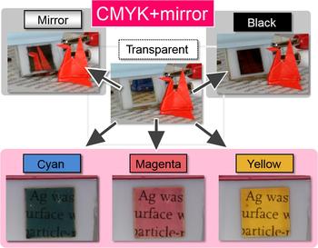
Among these methods achieving mulch-color EC devices, we are focusing on color change of metal nanoparticles induced by localized surface plasmon resonance (LSPR).[Reference Yokogawa, Burgos and Atwater10–Reference Kumar, Duan, Hegde, Koh, Wei and Yang12] Recently, we have reported multicolor EC device using LSPR of silver metal. This device achieved six optical states—transparent, silver-mirror, black, cyan, magenta, and yellow—in a single device on the basis of an electrochemical Ag deposition mechanism.[Reference Araki, Nakamura, Kobayashi, Tsuboi and Kobayashi13–Reference Onodera, Tsuboi, Nakamura and Kobayashi16] The Ag deposition-based EC device for reversible electrodeposition systems are basically composed of a pair of transparent electrodes with a gel electrolyte containing Ag+ between them. The application of a negative voltage causes the Ag metal deposition on the electrode substrate to construct metal nanoparticles or thin film that alters the optical properties of the surface. Optical colors—mirror, black, and three primary colors of cyan, magenta, yellow—can be changed controlling the shape and size of silver deposition (Fig. 1).
Photographs of Ag deposition-based multi-color device.

The default state of this device is transparent, whereas by applying a negative voltage to either one of the electrodes, Ag is electrodeposited on the electrode surface. Following Ag deposition on the flat Indium Tin Oxide (ITO) electrode under application of constant voltage, the device becomes a mirror. Conversely, when Ag deposition occurs on the ITO particle-modified electrode, which has a rough surface, the device turns black. On the other hand, Ag deposit with uniform particle size shows chromatic color states due to light absorption by LSPR. The uniform silver particle size is achieved by using a voltage step method.[Reference Sandmann, Dietz and Plieth17–Reference Safavi, Maleki and Farjami19] This method is consisted of application of two successive different voltages of first voltage V 1 to initiate Ag nucleation and second voltage V 2 to promote the growth of the Ag nuclei. Forms of Ag deposit varies by controlling the voltages and application times of V 1 and V 2. Ag nanoparticles deposited on a flat ITO electrode for which particle size dilatators are about 37 nm show magenta state. Then, these particles grow and construct Ag thin film state. The thickness of the thin film reaches about 54 nm by following V 2, it shows cyan state. Ag nanoparticles deposited on the ITO-modified electrode for which size diameters are about 10–20 nm show yellow state. The color of the devices can also be bleached by applying voltage for oxidation of the Ag deposit, leading to the initial state of transparent condition.
However, the Ag deposition-based multicolor EC device did not have enough color retention property. The color retention properties are greatly desired for practical applications of the EC devices such as smart windows and electronic papers. For example, smart windows, which maintain the comfortable environment of the room in terms of brightness and temperature, is expected as an energy-saving device contributing to reduce power consumptions of the air conditioner.[Reference Wang, Wu, Meng, Zhang and Wei20–Reference Lampert26] For reducing energy consumption, color retention property of the EC device is an essential function for smart windows. Similarly, electronic papers, a kind of reflective display, also need the color retention property for long time use without battery charging.
This poor memory property is due to Cu2+ ions, which are contained in the electrolyte solution of the device. Copper ion has two functions in the EC device. First, Cu2+ works as a reaction material on the counter electrode to compensate the charge consumed on the working electrode. The redox reaction (Cu2+ + e− ⇄ Cu+) on the counter electrode should compensate the reaction of redox of silver (Ag ⇄ Ag+ + e−) on the working electrode. Second, function of the Cu2+ is as an electrochemical mediator of the redox of silver for reducing the driving voltage of the EC device.
However, Cu2+ contained in the electrolyte causes oxidative dissolution of Ag deposit. The reduction potentials of Ag0 and Cu2+ in dimethyl sulfoxide (DMSO) solution were described below.
 $${\rm A}{\rm g}^{\rm +} + {\rm e}^ - \to {\rm A}{\rm g}^0: - 0.9\;{\rm V}\; ({\rm versus \;Ag}/{\rm A}{\rm g}^ + {\rm in\; DMSO}),$$
 $${\rm C}{\rm u}^{{\rm 2} +} + {\rm e}^ - \to {\rm C}{\rm u}^ +: - 0.{\rm 25}\;{\rm V}\; ({\rm versus \;Ag}/{\rm A}{\rm g}^ + {\rm in\; DMSO}).$$
Therefore, Cu2+ ion contained in the electrolyte causes oxidative dissolution of Ag0 deposit as shown in the following equation:
 $$ {\rm A}{\rm g}^0 + {\rm C}{\rm u}^{{\rm 2} + } \to {\rm A}{\rm g}^ + + {\rm C}{\rm u}^ +.$$
For these reasons, it was difficult to maintain Ag0 deposit without application of electrical potential or voltage.
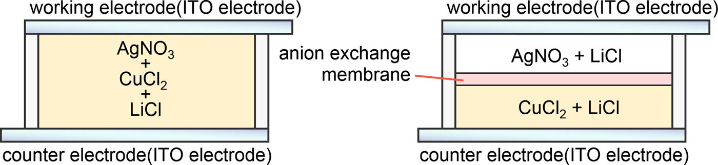
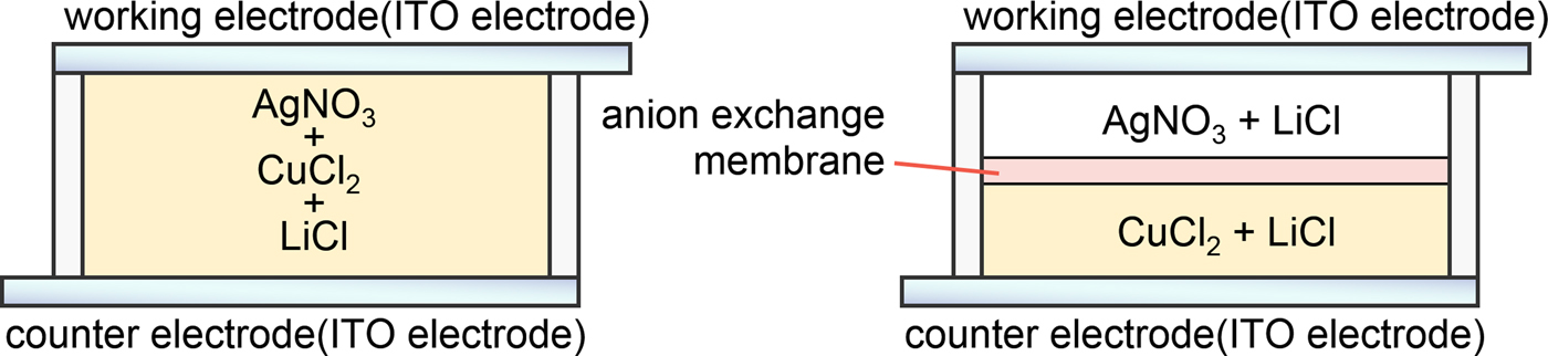
For various kinds of the EC devices, the memory functions at colored state are greatly desired as mentioned earlier. To achieve both good redox reactivity on the counter electrode and memory function, we introduced anion exchange membrane into the EC device (device configurations are shown in Fig. 2 right). Conventional EC device (Fig. 2 left) is constructed by sandwiching gel electrolyte containing Ag+ and Cu2+ between two ITO electrodes. The improved device contains anion exchange membrane between two ITO electrodes. In the working electrode side, only Ag+ and supporting electrolyte are placed; Cu2+ are not contained in this side. In the counter electrode side, on the other hand, only Cu2+ and supporting electrolyte are contained without Ag+. The anion exchange membrane would separate these cation species of Ag+ at working electrode side and Cu2+ at counter electrode side. In this paper, electrochemical characteristics of the two EC devices shown in Fig. 2 were investigated and evaluations of color retention properties were performed.
Structure of the EC devices. The device without anion exchange membrane (left) and the device with anion exchange membrane (right).
Experimental
Materials
Silver nitrate (AgNO3, Kanto Chemical Co. Inc., Japan), copper chloride (CuCl2, Kanto Chemical Co. Inc., Japan), and DMSO (Sigma Aldrich Japan, Japan) were used as received. Lithium chloride (LiCl, Kanto Chemical Co. Inc., Japan) was used as a supporting electrolyte without further purification. Poly (vinyl butyral) (PVB, Sekisui Chemical Co. Ltd., Japan) was used as a host polymer for electrolyte gelation. The ITO electrode (<10 Ω/□) was used after adequate washing with pure water and acetone. Anion exchange membrane (SELEMIONTM DSV, Asahi Glass Co. Ltd., Japan) was used in a swollen state.
Sample preparation
The gel electrolyte for the EC device without anion exchange membrane was prepared as follows: AgNO3 (100 mM) as EC material, LiCl (500 mM) as supporting electrolyte, and CuCl2 (50 mM) as electrochemical mediator were dissolved in DMSO. Subsequently, 10 wt.% of PVB as host polymer was mixed into the DMSO-based electrolyte solution. The gel electrolytes for the EC device with anion exchange membrane were prepared as follows: AgNO3 (100 mM) as EC material and LiCl (500 mM) as supporting electrolyte were dissolved in DMSO (for the solution at working electrode side). CuCl2 (50 mM) as counter reaction material and LiCl (250 mM) as supporting electrolyte were dissolved in DMSO (for the solution at counter electrode side). Subsequently, 10 wt.% of PVB as a host polymer was mixed into the DMSO-based each electrolyte solution. Anion exchange membrane was kept in a swollen state by dipping in electrolyte solution (250 mM LiCl in DMSO) for 12 h.
Fabrication of the EC device
The EC device without anion exchange membrane (Fig. 2, left) was constructed by sandwiching the PVB-based gel electrolyte between two flat ITO electrodes, maintaining the inter-electrode distance of 500 µm with a Teflon spacer. The EC device having anion exchange membrane (Fig. 2, right) was constructed by sandwiching gel electrolyte containing Ag+ ions, anion exchange membrane, and gel electrolyte containing Cu2+ ions. The distances between ITO electrodes and anion exchange membrane were maintained 200 µm with Teflon spacers, respectively. The thickness of the anion exchange membrane is 100 µm. Therefore, the distance between two electrodes of the EC device with ion exchange membrane is to be 500 µm as same as the EC device without ion exchange membrane. The active areas of both devices were 1 cm2.
Apparatus
Cyclic voltammetric measurement was carried out using a potentiostat/galvanostat (ALS, 660A, CH Instruments Inc., USA) equipped with a computer. Absorption spectra were recorded by on a diode array detection system (USB2000, Ocean Optics, USA).
Results and discussion
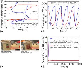
First, we investigated electrochemical and optical properties of the two devices. Figure 3(a) shows cyclic voltammograms of the two-electrode EC devices and change in transmittance during voltage sweep. In the case of the conventional EC device without anion exchange membrane, when applied voltage was scanned to negative direction, the device showed cathodic current based on the reduction of Cu2+ with the peak at −0.5 V (Cu2+ + e− →Cu+). Subsequently, cathodic current of electrochemical Ag deposition appeared and corresponding decrease of the transmittance was observed from −1.3 V. When the voltage was swept to a positive direction from −2.3 V, the EC device showed anodic current based on the oxidative dissolution of Ag deposit and corresponding increase of transmittance was observed from −0.5 V.
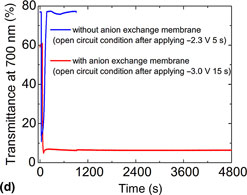
(a) Change in the transmittance at 700 nm (top) and cyclic voltammograms (bottom) of devices, (b) change in the transmittance at 700 nm accompanying constant voltage application of devices, (c) photographs of the transparent state (applied voltage of +1.5 V 45 s) and mirror state (applied voltage of −3.0 V 30 s) of the device with anion exchange membrane, and (d) change in the transmittance of two devices under open circuit states.

On the other hand, for the EC device with anion exchange membrane, when applied voltage was scanned to negative direction, cathodic reaction based on electrochemical Ag deposition and corresponding decrease of the transmittance were observed from −1.5 V. When the voltage was scanned to a positive direction from −2.8 V, anodic reaction based on oxidative dissolution of Ag deposit and corresponding increase of transmittance was observed from −0.4 V. Cathodic current based on the reduction of Cu2+ was not observed for this device, different from the conventional device without anion exchange membrane. It suggests that the anion exchange membrane prevents Cu2+ diffusion into the working electrode side. In spite of the wide sweep range and slow sweep speed, the change in transmittance of the EC device with anion exchange membrane was smaller than that of the EC device without anion exchange membrane. This small transmittance change would be due to the small amount of current flow in the EC device with ion exchange; i.e., amount of electrochemically reduced Ag deposit in the EC device with the membrane was smaller than that in the EC device without a membrane. These results are indicating that the EC device with ion exchange membrane has higher resistance, which is caused by anion exchange membrane. Now we are investigating detailed impedance measurements of the EC systems in order to clarify the resistance and redox mechanism of the EC device with ion exchange membrane. These results will be reported in near future.
It is significant that the transmittance of the device can be changed which is highly reversible owing to the function of Cu2+ as the complemental redox reaction material in the counter electrode side. Then, in order to discuss reversibility of the transmittance change of the EC device with anion exchange membrane, the coloration voltage of −3.0 V (30 s) and bleaching voltage of 1.5 V (45 s) were alternately applied. Figure 3(b) shows changes in the transmittance at 700 nm during consecutive voltage application. The transmittance change of the device without anion exchange membrane accompanying the application of the coloration voltage of −2.0 V (10 s) and bleaching voltage of 0.3 V (30 s) was also shown in Fig. 3(b) for the purpose of reference. For the device with anion exchange membrane, in the initial state, the transmittance was approximately 60%; the appearance of the device was transparent as shown in Fig. 3(c) left. By applying −3.0 V for 30 s, the transmittance decreased to 7%, resulting in a reflective state [Fig. 3(c) right]. After the coloration, the transmittance returned to initial value within 25 s by applying +1.5 V. The EC device showed relatively reversible color change during a few dozen times. It was confirmed that the change of the optical state of the EC device with anion exchange membrane could be reversibly controlled by applying suitable driving voltage. Comparing two devices, the device with anion exchange membrane needs higher voltage and longer time to color change. This is due to the resistance of anion exchange membrane. Furthermore, the transmittance in the transparent state in the film-equipped device is lower than that in the filmless device. This difference in transmittance is also due to the anion exchange membrane.
Finally, the retention times of the colored states of the two EC devices in open circuit condition (i.e., no electric power was applied) were investigated. The color retention property of the EC device under open circuit state was measured after few cycles of color changing. Figure 3(d) shows a change in transmittance of two devices at open circuit condition after Ag deposition. As discussed in Fig. 3(a), because the driving voltage and current flow in the two devices were different, we applied −2.3 V for 5 s for membrane-less EC device and −3 V for 15 s for the EC device with the membrane. By using this driving procedure, the consumed charge amounts of both devices were approximately 35 mC. The transmittance of both devices also became roughly the same amount (11% for the membrane-less device and 7% for the membrane-including device). For the conventional EC device without anion exchange membrane, the transmittance was 77% in the initial state. Then, the transmittance of the device decreased to 11% by applying −2.3 V for 5 s. After the coloration, the electrical voltage was shut off, and then the transmittance of the device was monitored under open circuit condition. As a result, the transmittance rapidly returned to initial state within 150 s. This was due to oxidative dissolution of Ag deposit by Cu2+ including in the electrolyte. On the other hand, for the EC device in which anion exchange membrane was introduced, the transmittance was 60% in the initial state. The transmittance decreased to about 7% by applying −3.0 V for 15 s. After that, the retention time of colored state was measured under open circuit condition. Interestingly, the transmittance at the colored state of the device did not return and kept the mirror state even after 4800 s, achieving longer retention time of colored state. After a few dozen times of color changes, this device kept the color retention property over 1 h. However, the speed of transmittance change became slower and amount of transmittance change also became smaller after few tens of cycles. This might be because part of silver ions and copper ions pass through the anion exchange membrane. To increase the stability of reversible color changing, it is important to optimize the type of ion exchange membrane and membrane thickness.
Conclusion
We constructed Ag deposition-based EC device with a novel configuration that was utilizing anion exchange membrane. The novel device effectively prevented approaching Cu2+ ions to Ag deposit, while copper ions worked as a counter redox material on the counter electrode. As a result, the Ag deposition-based novel EC device successfully achieved long retention time of colored state. The memory property is an effective power saving drive in devices such as smart windows, digital signage, information displays, and e-paper using Ag deposition-based EC device.
Acknowledgment
This work was partially supported by JSPS KAKENHI Grant No. 15H03880 and JST A-STEP (AS2811901S, AS2915036S).