I. INTRODUCTION
Nowadays, the use of lead-free solder material in electronic device is a major tendency in industries. It is an active response to the growing environmental concern about toxic lead contained electronic products. However, lead-free solder replacement calls for higher reflow temperature owing to its increased melting point. The temperature-induced vigorous reaction with conventional under bump metallization (UBM) dramatically threatens joint reliability. In electronic packaging manufacture, electroless deposited Ni–P layer has been widely used as a surface finish to form interconnections in electronic components. Reference Tu and Zeng1–Reference Liu and Shang4 Compared with copper substrate, Ni–P layer has many advantages, such as uniform thickness, maskless plating process, low consumption rate, low cost, and good wettability. Forthcoming nanoelectronic device era calls for evolving fine-pitch components. Its induced thermal aggregation in much smaller dimension puts excessive pressure on the interfacial reaction between surface finish and solder. The solder-reaction-assisted crystallization triggers the formation of P-rich layer and ternary Ni–Sn–P compound at the interface between solder and Ni-based UBM, resulting in phosphor aggregation-induced columnar voids and cracks between solder and UBM. Reference Jang, Kim, Tu, Frear and Thompson5 UBM loses its barrier properties as its structure becomes crystalline. When the undesired Ni–Sn–P phase forms at the interface, the Ni3Sn4 intermetallic compound (IMC) phase starts to grow separately from UBM. This phenomenon is defined as IMC spalling. Reference Liu, Chen, Mal and Tu6 The IMC spalling in turn accelerates the crystallization of P-rich layer and deteriorates the metallurgical bonding as well. Both, the void formation and IMC spalling become the root cause for the brittle fracture of IMC and lead to potential degradation of solder joint reliability. Reference Liu, Chen, Mal and Tu6,Reference Kim, Jang, Lee and Tu7 Therefore, the approaching challenge induced by dimensional scale down of component asks for the next-generation interconnect with superior performance.
Two approaches have been adopted by Gain et al. Reference Gain, Chan and Yung8 and Yang et al. Reference Yang, Balaraju, Huang, Liu and Chen9,Reference Yang, Balaraju, Chong, Xu, Liu, Silberschmidt and Chen10 to enhance solder joint reliability. First, the nanoparticle doping in solder matrix has been widely investigated. These adopted materials with nano or micro size can be divided into three types. Metal materials, such as Ni, Zn, Co, In Reference Shen and Chan11,Reference Zhao, Ma, Zuo, Liu and Guo12 ; metallic oxides, such as Al2O3, TiO2; and nonmetallic materials, such as silicon, carbon nanotube, graphene. Reference Gain, Chan and Yung8,Reference Hu, Chan, Zhang and Yung13 These materials have successfully dispersed in solder matrix and reinforced the interconnection with their individual characteristics. Another method to boost performance of the solder joint is to modify the UBM structure and material. Sputtered Ni(V) layer is widely used in UBM with Al/Ni(V)/Cu Reference Liu, Tu, Sheng, Tung, Frear and Elenius14 and Au/Pd/Ni–P Reference Tseng and Duh15 structures. What is more, the Ni–W–P and Ni–Co–P composite coating has been developed as novel UBM. The result showed that interfacial reaction between UBM and lead-free Sn–3.5Ag solder had been significantly retarded. In addition, void formation was suppressed after using the novel UBM. Reference Yang, Balaraju, Huang, Liu and Chen9,Reference Yang, Balaraju, Chong, Xu, Liu, Silberschmidt and Chen10 Gu et al. has incorporated carbon nanotube in electroless Ni–P layer, and this composite coating has successfully decreased the growth rate of P-rich layer and Ni3Sn4 IMC layer. Reference Gu, Chan, Yang and Wu16
A potential way using nanoparticle doping to UBM modification is proposed in this study. ZrO2 nanoparticles have already been used in solder matrix to refine the microstructure of grains. Reference Gain, Fouzder, Chan and Yung17 Therefore, ZrO2 nanoparticles can also be incorporated to the Ni–P layer to form Ni–P–ZrO2 composite coating by electroless deposition. This Ni–P–ZrO2 layer was first used as UBM in electronic packaging. The interfacial reaction between Ni–P–ZrO2 and lead-free solder alloy has been systematically investigated. The atom diffusion-induced microstructure evolution of the joints was analyzed after different aging conditions. The growth kinetics and activation energies of IMC formation were estimated. The effect of ZrO2 on interface was highlighted with comparison. In addition, the shear test was conducted to evaluate the mechanical property of the solder/Ni–P–ZrO2 joint.
II. EXPERIMENTAL
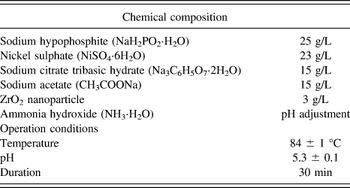
Zirconium dioxide nanoparticles with dimensions of 50 nm were bought from Aladdin Co., Ltd. Cu foils (5-mm thick, 99.97 wt%) were used as the substrate for both Ni–P and Ni–P–ZrO2 plating. The Cu substrates were polished and etched with 35 vol% nitric acid for 30 s, followed by a commercial Pd activation treatment for surface activation. The Ni–P–ZrO2 plating bath was prepared by dispersing ZrO2 nanoparticles into the Ni–P plating bath. The chemical composition and its operating conditions are shown in Table I. The concentration of ZrO2 nanoparticles in the plating solution was optimized by previous experiments. The ZrO2 nanoparticle in solution was first ultrasonically processed for 1 h to avoid agglomeration, followed by magnetic stirring at 500 rpm for 40 min to ensure its uniform dispersion in the Ni–P plating bath. The Ni–P plating bath without ZrO2 nanoparticle was used for prime Ni–P layer (17.5 at.% of P) deposition by comparison. Then, both deposited layers were tested by an x-ray diffractometer (XRD) with Cu Kα source (Philips X'Pert Pro MPD, PANalytical B.V., Almelo, Netherlands) for phase identification. Sn–3.5Ag layer was electroplated on the Ni–P and Ni–P–ZrO2 layer to form a solder joint. The soldering process was carried out in an 8-zone-forced convection reflow oven (BTU Pyramax 100N, North Billerica, MA). The reflow profile was set with a peak temperature of 250 °C; and the time above the melting temperature of the solder was about 70 s.
Chemical composition and operating conditions of the plating bath.

For the interfacial microstructure characterization, the samples were mounted in resin and cross-sectioned by carefully grinding toward the center using sand paper of different grit sizes followed by polishing with 0.5-µm alumina suspension. Finally, the solder/UBM interfacial microstructure was observed using SEM under back-scattered electron (BSE) imaging mode. An energy dispersive x-ray spectrometer (EDX, International, Model No. DX-4, FEI, Hillsboro, OR) was utilized to perform the semi-quantitative analysis on the microstructures to determine the chemical composition and the phase. Leica LAS V3.8 image process software was used to measure the average thickness, which was obtained through dividing the measured area by the horizontal length.
The wettability test was done using solderability tester (MENISCO ST 30). During the test, the liquid Sn–3.5Ag solder was kept at a constant temperature of 250 °C. The immersion speed, depth, and time were 21 mm/s, 3.0 mm, and 10 s, respectively. For each test, five samples were measured and the average value was studied. Typical wetting curves as a function of wetting time were proposed for analysis.
To measure the shear strength, ball shear tests were performed on samples after aging for different time spans using a shear-testing machine (DAGE Series 4000 Bond tester, UK) with a test speed of 350 µm/s. The diameter of the contact interface was 0.17 mm2. The fracture surfaces and compositions were investigated thoroughly using SEM under secondary electron (SE) imaging mode. Shear stress testing of 30 solder balls was undertaken at each condition, with minimum and maximum values removed.
III. RESULTS AND DISCUSSION
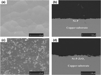
Figure 1 depicts the morphology and cross-section of as-deposited Ni–P and Ni–P–ZrO2 layers. The Ni–P layer has smooth nodules with different sizes. The formation of close-packed nodules is due to the characteristic of thin film growth mechanism by electroless deposition. Reference Mallory and Hajdu18 In Fig. 1(c), the distinguished ZrO2 nanoparticles are observed on the surface with uniform distribution. Despite slight aggregation, the ZrO2 have dispersed well with the help of magnetic stirring and ultrasonic treatment. From cross-section, the Ni–P layer in Fig. 1(b) shows a flatter and smoother surface than Ni–P–ZrO2 layer in Fig. 1(d). According to EDX, Both Ni–P and Ni–P–ZrO2 layer have similar P concentration of around 17.5 at.%. Moreover, both layers have a good adhesion to the copper substrate without any voids at interface.
Top view morphology and cross-section image of as-deposited (a, b) Ni–P layer and (c, d) Ni–P–ZrO2 layer.

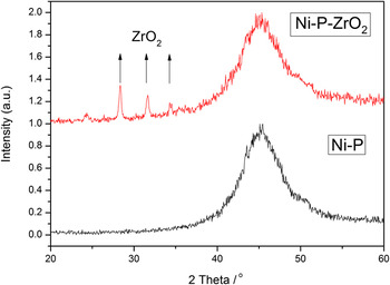
Figure 2 shows the XRD pattern of both Ni–P and Ni–P–ZrO2 under bump metallization. A board peak centered 2θ at around 45° are signs of Ni (1,1,1) phase in both Ni–P and Ni–P–ZrO2 layers. It indicates that both kinds of UBM have an amorphous structure. However, several new peaks at 25.3°, 28.2°, 33.6° and 34.9° appeared at Ni–P–ZrO2 layer, referring to a mixed monoclinic and cubic ZrO2 phase according to 37–1484 standard card from the JCPDS. 19 This result promotes ZrO2 nanoparticles have successfully inlaid into UBM with uniform dispersion.
X-ray diffraction patterns of Ni–P (lower) and Ni–P–ZrO2 (upper) coatings.

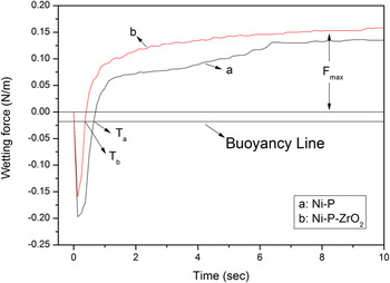
To see the solderability of the electroless deposited layer, quantitative solderability of Ni–P and Ni–P–ZrO2 layer was investigated. The typical wetting curves for Ni–P and Ni–P–ZrO2 in the as-deposited state are shown in Fig. 3 using the Sn–3.5Ag eutectic solder as the wetting liquid phase. The maximum wetting force is defined as the static force when the equilibrium state during the wetting process was reached. Reference Martorano, Martorano and Brandi20 The measured Ni–P layer has a maximum wetting force of 0.136 N/m, and the Ni–P–ZrO2 layer shows a higher maximum wetting force of 0.158 N/m. The T a and T b in Fig. 3 are defined as wetting time to the zero force, which is the cross-point of the wetting curve and buoyancy line. Reference Guo, Xian and Shang21 The wetting time of Ni–P–ZrO2 is 0.4 s shorter than that of the Ni–P layer indicating with the addition of ZrO2 nanoparticle on the UBM, the wetting speed has been increased. The improved solderability of Ni–P–ZrO2 refers to that the Ni–P layer may be explained by several reasons. First, the Ni–P–ZrO2 UBM has a rougher surface than the Ni–P UBM, and the contact surface area between liquid phase and solid phase was enlarged. The chemical reaction between solder and UBM could be more efficient as a result. Second, the uniformly distributed ZrO2 nanoparticles were chemically stable during interfacial reaction and do help to control atom diffusion at interface, they would help to pin the wetting front to avoid over-reaction at the interface.
Wetting curves of Sn–3.5Ag solder on UBM.

Figure 4 is as-reflowed SEM micrographs of the cross-sectional and top views of IMC formed between solder and UBMs. Intermetallic compounds formed in both kinds of reaction couples were identified to be Ni3Sn4 by EDX. In Fig. 4(a), a very thin layer of Ni3Sn4 phase formed in a layer shape with some protuberances at the solder/Ni–P interface. In Fig. 4(c), the needle-like Ni3Sn4 phase was formed as a result of reaction between solder and Ni–P–ZrO2 UBM. Both IMC layers in Figs. 4(a) and 4(c) have almost the same thickness. No void was detected at the interface, however, from the top view of IMC layer; Ni3Sn4 phases above UBM have varied morphology. In Fig. 4(b), IMC was small chunk-type with almost average size except for several irregular bulk Ni3Sn4 phases. The grain size is larger than that of ZrO2 doped reaction couple in Fig. 4(b). The Ni3Sn4 phase in solder/Ni–P–ZrO2 joint was in a typical needle-like shape with uniform dimension.
SEM micrographs of the cross-sectional and top views of IMC in as-reflowed (a, b) solder/Ni–P and (c, d) solder/Ni–P–ZrO2 joints.

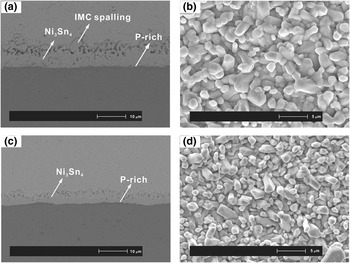
Figure 5 shows the micrograph of cross-sectional and top views of IMC in solder/Ni–P and solder/Ni–P–ZrO2 joints after aging at 160 °C for 225 h. With the extension of the isothermal aging time, the thickness of the IMC phase as well as the grain size in both reaction couples had grown dramatically. Compared with the IMC of plain joint, the ZrO2-incorporated joint showed a smaller thickness. The slight IMC spalling was detected at solder/Ni–P interface as shown in Fig. 5. Bulk IMC phase has grown away from the interface into the solder matrix. The IMC morphology of solder/Ni–P joint remained the dominant chunky shape in Fig. 5(b). In solder/Ni–P–ZrO2 joint, the small needle-like IMC has been no longer observed and transformed to scallop-like protrusions into the solder matrix with larger sizes as shown in Fig. 5(d). The Ni3Sn4 phase in solder/Ni–P–ZrO2 displayed a variety of grain sizes with faceted surfaces. The facet is ascribed to anisotropic interfacial energy of the IMC phase. Reference Chen, He and Qi22 A very thin layer of P-rich phase was detected in both reaction couples as shown in Figs. 5(a) and 5(c). The EDX result showed these P-rich layers contained 16.3 ± 1 wt% P and 83.7 ± 1 wt% Ni. To provide sufficient Ni atoms to form Ni3Sn4 phase, UBM faced with a number of Ni atoms loss. The depletion of Ni assisted the transformation of amorphous Ni–P layer into a crystalline P-rich phase. For both kinds of reaction couples, the grain size of IMC kept on increasing and the total quantity of grains decreased during solder/UBM interaction. However, the IMC grain size of Ni–P was still larger than that of Ni–P–ZrO2. Kim and Tu Reference Kim and Tu23 explained the phenomenon of grain coarsening using mechanism of diffusion flux and ripening flux. It is proposed that the large quantity of adjacent Ni3Sn4 grains happen to maintain similar crystallographic orientation, and these grains have a high chance to coalesce with each other, resulting in the formation of larger grains. From the microstructure, ZrO2-doped UBM has successfully suppressed grain coarsening and refined the IMC phase compared with plain UBM
SEM micrographs of the cross-sectional and top views of IMC in (a, b) solder/Ni–P and (c, d) solder/Ni–P–ZrO2 joints after aging at 160 °C for 225 h.

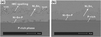
Figure 6 shows the solder/Ni–P and solder/Ni–P–ZrO2 joints after aging at 180 °C for 625 h. The thickness of the Ni3Sn4 phase was 13.7 and 8.9 μm for plain reaction couple and ZrO2-doped reaction couple, respectively. The IMC at solder/Ni–P interface shows a higher growth rate than that of solder/Ni–P–ZrO2. In addition, serious IMC spalling was observed at the solder/Ni–P interface as shown in Fig. 6(a). The Ni3Sn4 phases of square or cubic shape were extruded from the formal IMC layer into the bulk solder. Simultaneously, micro voids were formed among the spall of the IMC. Figure 6(a) shows the visible micro voids on the top of the IMC layer in solder/Ni–P joint. The crystalline P-rich layer grew thicker at the expense of the amorphous Ni–P layer as shown in Fig. 6(a). However, the limited part of Ni–P–ZrO2 in Fig. 6(b) was transformed to P-rich phase. This indicated that the out-diffusion rate of Ni atoms from the Ni–P layer was accelerated as the reaction and aging processed. Nevertheless, Ni–P–ZrO2 successfully depressed the out-diffusion rate of Ni atoms to preserve the amorphous structure as the dominant in UBM.
SEM micrographs of the cross-sectional view of IMC in (a) solder/Ni–P and (b) solder/Ni–P–ZrO2 joints after aging at 180 °C for 625 h.

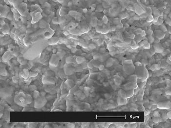
Figure 7 shows the top view of IMC phase in solder/Ni–P joint phase after aging at 180 °C for 800 h. The distinct voids are observed on the surface. It is speculated that the voids are caused by the serious IMC spalling phenomenon. The diffusion of Ni atoms into the solder matrix triggered the volume change at the IMC interface. The volume mismatch at the interface generated stress, resulting in void formation at the interface between phase and Ni phase. These voids would be highly possible to nucleate and propagate with prolonged aging time, and then gradually form cracks as a result. Voids formed at the interface of the solder/Ni–P joint would be a potential threat that may dramatically deteriorate the solder joint reliability.
SEM micrographs of the top view of IMC in solder/Ni–P joint after aging at 180 °C for 800 h.

In the present work, the growth kinetics of IMC in both solder/Ni–P and solder/Ni–P–ZrO2 joints were investigated. The growth process of Ni3Sn4 phase can be described by a typical parabolic equation Reference Chada, Laub, Fournelle and Guan24,Reference Lu, He, En, Wang and Zhuang25 given below:
 $$x - {x_0} = {(kt)^{1/2}}\quad {\rm{,}}$$
where x is the thickness of the IMC layer at time t and zero, respectively; t is the aging time; and k is the growth rate constant (cm2/s), which is also regarded as the diffusion coefficient of elements in the IMC layer. Both kinds of solder joints were aged at temperatures of 140, 160, and 180 °C in this study.
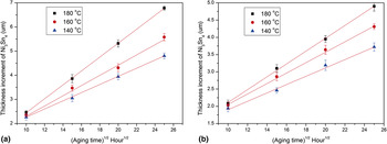
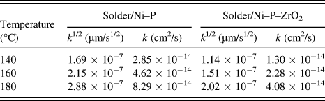
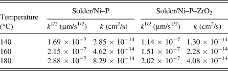
Figure 8 shows average IMC layer thickness increment (x − x 0) for solder/Ni–P and solder/Ni–P–ZrO2 joints as a function of the square root of aging time. The thickness increment of both layers was found to increase linearly with the square root of aging time, indicating that volume diffusion dominates the IMC growth process of both reaction couples. The value of k is determined from the slope of the linear regression line. The estimated k values of Ni3Sn4 in two kinds of joints are listed in Table II. The calculated growth constant increased with the aging temperature, which is consistent with higher thickness of IMC layer observed in micrograph. It is worth mentioning that with the addition of ZrO2 nanoparticle on the UBM, the growth constant of Ni3Sn4 layer decreased significantly.
Thickness of the IMC layer in (a) solder/Ni–P and (b) solder/Ni–P–ZrO2 joints during aging at 140, 160, and 180 °C up to 625 h.

Value of k determined from the slope of the linear regression.
To calculate the activation energy of IMC growth, the Arrhenius relationship is used as below
 $$k = {k_0}\exp \left( { - {Q \over {RT}}} \right)\quad {\rm{,}}$$
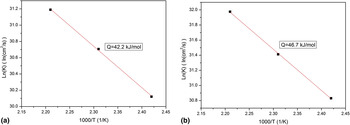
where k 0 is the constant growth rate (cm2/s), Q is the activation energy for IMC growth (kJ/mol), R is the ideal gas constant (8.314 J/mol K) and T is absolute temperature (Kelvin). The value of Q can be deduced from the slope of the Arrhenius plot as shown in Fig. 9. The activation energy of the IMC growth was estimated to be 42.2 kJ/mol for solder/Ni–P joint while 46.7 kJ/mol for solder/Ni–P–ZrO2 joint. The ZrO2 incorporated reaction couple showed a higher Q value, indicating that more energy was needed for the interfacial reaction between solder and UBM. In the previous study, we have estimated the activation energy of Sn–3.5Ag/Ni–P and Sn–3.5Ag/Ni–P–TiO2 joints. The result is relatively higher than the value in the present study. Reference Hu, Xu, Yang, Chen and Chan26 The first reason is that the different aging temperature used may lead to the deviation of Q-value. In addition, the different dimension of the contact area between solder and UBM also causes the difference of activation energy. In the present study, electrodeposited solder layer was used on UBM instead of the as-prepared solder ball in the previous study. As a result, the volume of the liquid phase in the reaction is different. Other researchers like Yoon et al. have calculated the Q value to be 49 kJ/mol for solder/Ni–P joint aged from 100 to 170 °C for up to 60 days. Reference Yoon and Jung27 Tu et al. Reference Tu, Chan, Hung and Lai28 estimated the Q value to be 45.5 kJ/mol after 36 days aging. Despite the difference in experimental conditions, the calculated activation energy in the present work is in the compatible range when compared with other works. Therefore, Sn diffusion in Ni3Sn4 proves to be the controlling mechanism for Ni3Sn4 phase growth similar to previous work. The function of ZrO2 nanoparticles on the Ni–P layer is to successfully retard the out-diffusion of Sn atoms from bulk solder toward the UBM thus leading to restricted supply of Sn atoms for interfacial reaction. As ZrO2 nanoparticle is a non-coarsening, non-reactive material, it may be adsorbed at the grain boundary, thus the relative relationship of growth rates among crystal orientations of the IMC is changed, leading to a suppression of the IMC layer growth. Finally the profound obstacle was formed to inhibit IMC layer growth.
Arrhenius plot of the growth of IMC layers in (a) solder/Ni–P and (b) solder/Ni–P–ZrO2 joints.

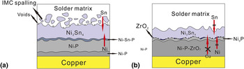
Figure 10 shows the schematic mechanism of the IMCs at the solder/Ni–P and solder/Ni–P–ZrO2 interface. Based on the EDX result, P atoms in both Ni–P and Ni–P–ZrO2 layers did not participate in the chemical reaction with solder while remained in the UBM. The continuous growth of the Ni3Sn4 phase attracts Ni atoms diffuse out from UBM. In Fig. 10(a), fast formation of IMC dramatically depleted Ni atoms in the Ni–P layer, gradually crystalline P-rich layer is formed instead of the amorphous Ni–P layer as a result of this process assisted crystallization. However, in Fig. 10 (b), the ZrO2 nanoparticles appeared on the Ni–P layer, blocked the diffusion path of Sn and Ni atoms to interface, and resulted in the decreased Ni3Sn4 layer thickness and less P-rich layer. The threat of the P-rich layer is that it has a structure with many fine grains, which can act as fast diffusion channel to enhance the interdiffusion of Ni and Sn atoms through a P-rich layer. After prolonged aging, Ni atoms start to diffuse though the Ni3Sn4 layer into the solder matrix to react with solder. The phenomenon of IMC spalling observed is shown in Fig. 6(a). It was reported that the root cause of spalling formation is the Ni–Sn–P phase near the P-rich layer. Reference Sohn, Yu, Kang, Shih and Lee29,Reference Kim, Yoon and Jeng30 This IMC spalling would in turn accelerate the crystallization of the P-rich layer. The spalling will cause IMC to detach itself from the interface and lead to weak adhesion of solder joints. In addition, voids formed at the edge of the IMC due to IMC spalling. The atom diffusion during IMC spalling process will lead to volume change. Stress will be generated at the interface, and voids are formed as a result of volume mismatch. As the ZrO2 appeared at the interface in Fig. 10(b), the interfacial atoms migration induced by unbalanced interdiffusion was hindered to alleviate the process-assisted crystallization. So no serious IMC spalling and voids were observed at the interface of the solder/Ni–P–ZrO2 joint. As a result, the formation of crystalline P-rich layer was decreased. The ZrO2 nanoparticles act as a barrier to slow down the interfacial reaction to avoid significant shrinkage of amorphous Ni–P–ZrO2 layer. The remaining amorphous structure without fast diffusion channel such as grain boundaries is very difficult for copper atoms to penetrate through. As a result, Ni–P–ZrO2 is deduced to outperform Ni–P for a superb barrier property to prevent copper diffusion from the substrate and thus reinforce the solder joint reliability.
Schematic mechanism of the interfacial IMCs at the solder/Ni–P and solder/Ni–P–ZrO2 interface.

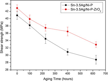
Besides the function as electrical path, solder joint often encounters external mechanical loading. Superior shear strength is essential to boost the reliability of electronic systems. To simulate in practical conditions of system use and processing, ball shear tests were conducted to evaluate the effect of ZrO2 reinforcement on the mechanical properties of solder/Ni–P joints as a function of aging time. Figure 11 plots the variation of the average shear strength of solder/Ni–P and solder/Ni–P–ZrO2 joints aged for different times. Both kinds of joints show declined shear strength as the aging time increases. This attributed to microstructural phase coarsening, volumetric shrinkage and thermal stress concentrations induced by excessively heating and cooling process of reflow. As a result, the mechanical properties of the solder joints degrade as shown in Fig. 11. For the as-reflowed reaction couples, the ZrO2 nanoparticle-doped couple has higher shear strength of 42.8 MPa, which is 2.1 MPa higher than that of solder/Ni–P joints. The average shear strength of solder/Ni–P–ZrO2 is consistently higher than that of solder/Ni–P joints during the whole aging period up to 625 h. The shear strength of solder/Ni–P–ZrO2 decreased only 21.5% by the end of prolonged aging, however, the shear strength decreased by 28.9% in the sample without ZrO2 nanoparticle addition for aging of 625 h. It is obvious that ZrO2 nanoparticles incorporated UBM demonstrated a lower decline rate of shear strength during prolonged aging. The plausible explanation for the reinforced mechanical reliability is the homogeneous distribution of ZrO2 nanoparticles on the UBM and controlled IMC layer thickness and morphology. The hindered IMC spalling in solder/Ni–P–ZrO2 joint also contributes to the improvement of mechanical property. The ZrO2 nanoparticles not only assist to impede the grain boundaries from sliding, but also suppress the dislocation movement and boosts dislocation densities. The rough and bumpy morphology of the as-deposited Ni–P–ZrO2 layer will provide a larger contact area to react with the solder. So, it is prone to establish a persistent and ductile solder interconnect thus superior to resist mechanical shock from practical operations.
Ball shear strength as a function of aging time for solder/Ni–P and solder/Ni–P–ZrO2 joints.

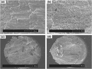
Fractographic analyses after shear test were conducted to investigate the variations of shear strength. Figure 12 shows the morphology of the fracture area after destruction for solder/Ni–P and solder/Ni–P–ZrO2 joint. Both kinds of as-reflowed reaction couples are able to keep bulk solder covering the fracture plane, and indicate that the joint bonding strength of IMCs was higher than the cohesive of bulk solder. In the reaction couples without ZrO2 addition, the fracture surface exhibited a brittle fracture mode with quite a smooth appearance as shown in Fig. 12(a). However, ZrO2 nanoparticle incorporated interconnect showed ductile transition failure, with big dimples and plastic deformation detected on the tensile plastic fracture as shown in Fig. 12(d). The formation of ductile appearance ascribed to the homogeneous distribution of ZrO2 nanoparticles on the UBM. In solder/Ni–P–ZrO2 joint, excessive growth of the intrinsically brittle Ni3Sn4 and P-rich layers with voids at interface could be responsible for the formation of brittle fractures, resulting in decreased mechanical property. Therefore, incorporated ZrO2 in UBM successfully hinders the formation of the brittle pattern, contributing to relieve the reliability issue of interconnect.
SEM fracture surfaces of solder/Ni–P (a, c) and solder/Ni–P–ZrO2 (b, d) joints after ball shear test.

IV. CONCLUSION
To reinforce the reliability of UBM in a solder joint, ZrO2 nanoparticles were successfully incorporated in electroless Ni–P layer as. Ni–P–ZrO2 coating becomes an alternative of traditional Ni–P metallization for lead-free interconnect. Interfacial reaction between Ni–P–ZrO2 and electroplated tin was intensively investigated with prime Ni–P layer used as a benchmark. Solderability test of the Ni–P–ZrO2 layer showed an improved performance. The reaction couples were prolonged, aged under different temperatures to evaluate the IMC layer growth kinetics and the activation energy. With the help of ZrO2 nanoparticle addition, the growth of Ni3Sn4 phase and IMC spalling are suppressed, so are the void formations. The top view of IMC in the solder/Ni–P–ZrO2 joint demonstrated a much finer grain size compared with that in the solder/Ni–P joint. Based on IMC growth, the activation energy of solder/Ni–P–ZrO2 was estimated to be 46.7 kJ/mol, higher than 42.2 kJ/mol of plain solder joint. A reactive diffusion-induced compound formation mechanism was proposed to explain the effect of ZrO2 nanoparticles on the interfacial reaction. ZrO2 nanoparticles act as a barrier to block the out-diffusion of Ni atoms and result in a retarded interfacial reaction. Moreover, solder/Ni–P–ZrO2 demonstrated higher shear strength than that of solder/Ni–P throughout the prolonged aging. The shear strength of solder/Ni–P–ZrO2 declined only 21.5% by the end of aging. The fracture of solder/Ni–P–ZrO2 after shear test showed ductile transition failure, with big dimples and plastic deformation detected on the tensile plastic surface. As a consequence, Ni–P–ZrO2-doped UBM with superb barrier property and reinforced mechanical property would be a competitive candidate as a novel UBM in lead-free soldering.
ACKNOWLEDGMENTS
The authors would like to acknowledge the financial support provided by the Research Grants Council, Hong Kong, ref. no. 9041636 (A study of nanostructured electronic interconnects-preparation, characterization and integration), City University of Hong Kong research project: 7002848 (A study of functionalized CNT/graphene reinforced composite electronic interconnects: preparation, characterization and integration for green nanoelectronic applications), the Center for Electronic Packaging and Assemblies, Failure Analysis and Reliability Engineering (EPA Center) of City University of Hong Kong, Chartermate International Ltd. for help the electroplating process.