Nomenclature
-
 ${\bf{M}}$
-
Mass matrix (or inertial matrix)
- [
$u,v,w,p,q,r$
]
-
linear velocities and angular velocities in BRF, m/s
-
${{\bf{F}}_{{\bf{GB}}}}$
-
gravity and buoyancy force, N
-
${{\bf{F}}_{\bf{I}}}$
-
Coriolis force, N
-
${{\bf{F}}_{\bf{A}}}$
-
aerodynamic force, N
-
${x_G},{y_G},{z_G}$
-
positions of gravity centre, m
-
$m$
-
mass of the airship, Kg
-
${m_{11}}, \ldots ,{m_{66}}$
-
added masses of the airship, Kg
-
${I_x},{I_y},{I_z}$
-
inertial moments, Kg.m2
-
$G,B$
-
gravity, buoyancy, N
-
${\bf{T}}$
-
control allocation matrix
-
${R_p}$
-
distance between the position of propeller and volume centre of the airship, m
-
${f_i}(i = 1,2,3,4)$
-
thrust of propeller i, N
-
${\mu _i}(i = 1,2,3,4)$
-
vectored angle of propeller i, rad
-
${f_{iH}},{f_{iV}}$
-
indirect input forces of propeller i, N
-
${{\bf{F}}_{\bf{T}}} = {[\begin{array}{*{20}{c}}{{f_x}} {\,{f_y}} {\,{f_z}} {\,{f_\psi}}\!\!\end{array}]^{\rm{T}}}$
-
direct input forces and moments of the propellers, N and N.m
-
$\varphi ,\theta ,\psi $
-
attitude of the airship
-
${\bf{J}}$
-
transform matrix


1. Introduction
As a type of lighter-than-air vehicle, the airship has gradually become a significant research object in recent years due to its wide applications, such as environmental monitoring, scientific exploration and broadcasting relays [Reference Lee1, Reference Munk2]. The advantages of the airship include the ability to hover at high altitude for long-time operation and apparent superiorities in payload capacity [Reference Lindstrand3, Reference Yokomaku4]. For long-time high-altitude workd, autonomous flight control technologies play key roles in airship development [Reference Smith, Lee and Fortneberry5–Reference Yang8]. However, the implementation of trajectory tracking control tasks in a hard environment with strong illumination, high radiation and large temperature difference between day and night [Reference Li, Fang and Dai9, Reference Chen and Duan10] leads to high likelihood of system breakdown and cannot be repaired manually in time. Therefore, the fault-tolerant control system (FTCS) is an urgent problem for future airship operation.
The existing efforts in FTCS design can be classified into two main approaches: passive and active. Robust control techniques are used to ensure that the closed-loop system remains insensitive to certain faults in the passive FTCS [Reference Benosman and Lum11], whereas a new control system is reordered according to the estimation of the Fault Detection and Isolation filter in the active FTCS [Reference Cieslak, Henry and Zolghadri12]. These systems have been subject to study for years. While fault-tolerant controller works well [Reference Fekih13, Reference Zhang and Jiang14], identifying real actuator faults remains difficult due to the nonlinear coupling effect [Reference Hu, Xiao and Zhang15, Reference Alwi and Edwards16]. Fault diagnosis methods can be basically divided into two categories: analytical model-based [Reference Sun, Liu and Zhang17, Reference Edwards and Tan18] and signal-processing-based [Reference Chen, Shi and Wen19, Reference Boskvic and Mehra20]. For the fault diagnosis of nonlinear systems, the analytical model-based approach is the most mainstream solution with its deep understanding of the system characteristics and real-time monitoring. However, its disadvantage is that the robustness of fault diagnosis is becoming increasingly prominent due to the inaccuracy of system modeling [Reference Chen, Yang and Guo21]. At present, current studies mainly adopt the signal processing-based method, which presents the advantage of avoiding the connection with the system and directly uses the real-time value of variables without considering the model accuracy. However, this method is only suitable for measurable states [Reference Chen, Jiang and Lu22, Reference Yu, Xu and Jiang23]. Until now, few studies have explored fault-tolerant control on airships.
Recently, a flat peach shape aerostat with four vectored propellers, named finless airship, was proposed [Reference Chen, Zhang and Duan24]. The vectored-thrust spheroid has advantages different from those of the traditional airship, such as an isotopic drag coefficient, lateral control, independent position and attitude control [Reference Chen, Duan and Sun25, Reference Chen, Whidborne and Dong26]. An observer-based actuator fault identification and tracking control for this multi-propeller aerostat is demonstrated in the present study. Real actuator faults are carried out by choosing proper control variables, and fault force is estimated from the model. The controller is only responsible for tracking, and the estimated fault force is compensated in the allocation module among multi-vectored propellers.
This paper is organised as follows. Section 2 introduces a full dynamic model of the multi-vectored thrust airship. Section 3 presents the four types of actuator faults individually and shows a synthesis fault model. Section 4 discusses the design of the fault-tolerant control and fault identification for the trajectory tacking. In the last section, a brief summary is concluded and future work is indicated.
2. Multi-propeller aerostat model
2.1 Multi-propeller aerostat
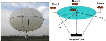
The multi-vectored propeller aerostat (see Fig. 1) has a flat peach shape and length–diameter ratio 0.6. The main body is a helium airbag, where the four vectored propellers are installed around and symmetrically [Reference Chen, Duan and Sun25]. The body coordinate system is shown in Fig. 1, the x-axis is located between two of the four propellers as frame oxy and its x-axis forms a 45º angle with one of the four propellers. The thrust of each propeller is
 $f$
, and in total, provide a total force of
 $2\sqrt 2 f$
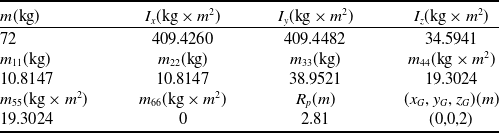
along the x direction in the oxy frame. Table 1 presents the airship model parameters.
Multi-vectored propeller aerostat and body-fixed coordinate.

Aerostat Model Parameters

2.2 Dynamics model
The pod and load are placed below the capsule, which can enhance the system stability to a certain extent. Thus, in this study, we assume that excursions in roll and pitch during flight are small enough and negligible. The position and yaw angle on the reference frame are
 ${\boldsymbol{\eta }} = {\left[ {\begin{array}{*{20}{c@{\quad}c@{\quad}c@{\quad}c}}x & y & z &\psi \end{array}} \right]^{\rm{T}}}$
while the state variables in the body frame are
 $\begin{array}{*{20}{c}}{{\bf{X}} = [u}\;\;\;\; v\;\;\;\; w\;\;\;\; r\end{array}{]^{\rm{T}}}$
, where
 ${[\begin{array}{*{20}{c}}u\quad v \quad w\end{array}]^{\rm{T}}}$
is the linear speed and
 $r$
is the yaw angular velocity in the coordinate system. The 4-DOF kinematic equation of the aerostat can be written as
 \begin{align}{\dot{\boldsymbol{\eta}}} = {\bf J}(\boldsymbol\eta ){\bf X}\end{align}
Here, the transformed matrix is
 \begin{align*}{\bf{J}}({\boldsymbol{\eta }}) = \left[ {\begin{array}{c@{\quad}c@{\quad}c@{\quad}c}{\cos \psi } & { -\!\sin \psi } & {\rm{0}}& {\rm{0}}\\[5pt]{\sin \psi } & {\cos \psi } & {\rm{0}} & {\rm{0}}\\[5pt]{\rm{0}} & {\rm{0}} & {\rm{1}} & {\rm{0}}\\[5pt]{\rm{0}} & {\rm{0}} & {\rm{0}} & {\rm{1}}\end{array}} \right].\end{align*}
The simplified four-degree-dynamics equation of the multi-propeller aerostat used for the controller design is
 \begin{align}{\bf{M}}{\dot{\rm X}}={{\bf{F}}_{{\bf{GB}}}}+{{\bf{F}}_{\bf{A}}}+{{\bf{F}}_{\bf{I}}}+{{\bf{F}}_{\bf{T}}},\end{align}
where
 ${\bf{M}}$
is the mass matrix, computed below:
 $m$
is the mass of aerostat;
 ${m_{11}}$
,
 ${m_{22}}$
,
 ${m_{33}}$
and
 ${m_{66}}$
are the added masses; and
 ${I_z}$
is the yaw inertia moment of the aerostat.
 \begin{align*}{\bf{M}} = \left[ {\begin{array}{*{20}{c@{\quad}c@{\quad}c@{\quad}c}}{m + {m_{11}}} & {\rm{0}} & {\rm{0}} & {\rm{0}}\\[5pt]{\rm{0}} &{m + {m_{22}}}& {\rm{0}}& {\rm{0}}\\[5pt]{\rm{0}}& {\rm{0}}& {m + {m_{33}}}& {\rm{0}}\\[5pt]{\rm{0}}& {\rm{0}}& {\rm{0}}& {{I_z} + {m_{66}}}\end{array}} \right]\end{align*}
The right-hand side of the equation denotes the external forces and moments, which includes gravity and buoyancy
 ${{\bf{F}}_{{\bf{GB}}}}$
, aerodynamic force
 ${{\bf{F}}_{\bf{A}}}$
, Coriolis force
 ${{\bf{F}}_{\bf{I}}}$
, and the thrust generated by the vectored propellers
 ${{\bf{F}}_{\bf{T}}}$
[Reference Chen, Zhang and Duan24].
2.3 Vectored propeller model
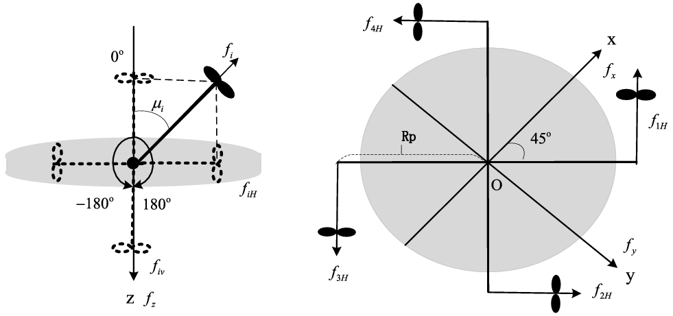
The local frame of the vectored propeller is established in the vectored-rotation plane (Fig. 2), in which the propeller can deflect around the axis at a range of
 $[\!-\!{180^{\rm{o}}},{180^{\rm{o}}}]$
. The vectored angle of each propeller is denoted by
 ${\mu _i} \in (\!- \pi ,\pi ),i = 1,2,3,4$
, and the generated force is represented by
 ${f_i} \in (0,20N)$
,
 $i = 1,2,3,4$
. In the vectored-rotation plane, the thrust can be decomposed into two orthogonal forces, namely, horizontal
 ${f_{iH}}$
and vertical
 ${f_{iV}}$
components, computed as
 \begin{align}\left\{ \begin{array}{l}{f_{iH}} = {f_i}\sin {\mu _i}\\[5pt] {f_{iV}} = - {f_i}\cos {\mu _i}.\end{array} \right.\end{align}
Vectored-propeller frame and decomposition.

This aerostat has four vectored propellers with eight control variables called indirect control force
 ${{\bf{f}}_{{\bf{HV}}}}$
:
 ${{\bf{f}}_{{\bf{HV}}}} = {\left[ {\begin{array}{*{20}{c}}{{f_{{\rm{1}}H}}}\;\;\;\; {{f_{{\rm{2}}H}}}\;\;\;\; {{f_{{\rm{3}}H}}}\;\;\;\; {{f_{{\rm{4}}H}}}\;\;\;\; {{f_{{\rm{1}}V}}}\;\;\;\; {{f_{{\rm{2}}V}}}\;\;\;\; {{f_{{\rm{3}}V}}}\;\;\;\; {{f_{{\rm{4}}V}}}\end{array}} \right]^{\rm{T}}}$
. Yaw and position are controlled by deconstructing orthogonal forces
 ${f_{iH}}$
and
 ${f_{iV}}$
into the body-fixed frame along the x-, y-, and z-axes Fig. (2). Therefore, the 3D thrusts and yaw moments in the body frame are deduced as
 \begin{align}{{\bf{F}}_{\bf{T}}} = {[\begin{array}{*{20}{c@{\quad}c@{\quad}c@{\quad}c}}{{f_x}}& {{f_y}}& {{f_z}}& {{f_\psi }}\end{array}]^{\rm{T}}} = {\bf{T}}{{\bf{f}}_{{\bf{HV}}}}\end{align}
where
 ${{\bf{F}}_{\bf{T}}}$
denotes the direct control force of the thrusters on the body,
 ${\bf{T}}$
represents the indirect control allocation matrix
 \begin{align*}{\bf{T}} = \left[ {\begin{array}{*{20}{c@{\quad}c@{\quad}c@{\quad}c@{\quad}c@{\quad}c@{\quad}c@{\quad}c}}{\dfrac{{\sqrt 2 }}{2}}& {\dfrac{{\sqrt 2 }}{2}} &{ - \dfrac{{\sqrt 2 }}{2}} &{ - \dfrac{{\sqrt 2 }}{2}}& 0 &0& 0& 0\\ \\[-7pt] { - \dfrac{{\sqrt 2 }}{2}}& {\dfrac{{\sqrt 2 }}{2}}& {\dfrac{{\sqrt 2 }}{2}} &{ - \dfrac{{\sqrt 2 }}{2}}& 0 &0 &0 &0\\ \\[-7pt] 0 &0& 0 &0 &1& 1 &1 &1\\ \\[-7pt] { - {R_p}} &{ - {R_p}}& { - {R_p}}& { - {R_p}}& 0& 0 &0 &0\end{array}} \right],\end{align*}
and
 ${R_p}$
is the distance from the position of the propeller to the volume centre of the body.
3. Vectored propeller faults modeling
The faults of the vectored propeller can be divided into four categories, including thrust offset (type 1), vectored angle offset (type 2), vectored angle stuck (type 3) and thrust efficiency loss (type 4). The thrust and vectored angle offset types cause a fixed initial offset on the vectored thrust and angle, respectively. The thrust efficiency loss represents that of output thrust magnitude. If the vectored angle is stuck, the propeller has a fixed direction. One fault type may occur in different propellers and one propeller may have different types of faults at the same time. Thus, single-type and multi-type faults synthesis are given to inspect the acting mechanism of faults on control force.
3.1 Single type fault model
In case of vectored thrust and angle offset faults, the indirect control forces of a single vectored propeller i are:
 \begin{align}\left\{ \begin{array}{l}f_{_{iH}}^r = (\,{f_i}+\Delta {f_i})\sin {\mu _i} = f_{_{iH}}^n+\Delta {f_i}\sin {\mu _i}\\[5pt]f_{_{iV}}^r = - (\,{f_i}+\Delta {f_i})\cos {\mu _i} = f_{iV}^n{\rm{ + (}}\! - \Delta {f_i}\cos {\mu _i})\end{array} \right.\end{align}
 \begin{align}\left\{ \begin{array}{l}f_{_{iH}}^r = {f_i}\sin ({\mu _i} + \Delta {\mu _i}) = f_{_{iH}}^n + {f_i}\cos {\mu _i}\Delta {\mu _i}\\[5pt] f_{_{iV}}^r = - {f_i}\cos ({\mu _i} + \Delta {\mu _i}) = f_{_{iV}}^n + {f_i}\sin {\mu _i}\Delta {\mu _i}\end{array} \right.\end{align}
respectively, where
 ${f_i}$
,
 ${\mu _i}$
is the nominal thrust magnitude and vectored angle of the propeller;
 $\Delta {f_i}$
,
 $\Delta {\mu _i}$
are the vectored thrust and angle offsets, which can be considered as small disturbances;
 $f_{_{iH}}^n$
,
 $f_{iV}^n$
are the nominal value of indirect control force from i propeller without faults; and
 $f_{_{iH}}^r$
,
 $f_{_{iV}}^r$
are the actual value of indirect control force with faults. The calculations show that the thrust offset induces indirect fault force
 $\Delta {f_i}\sin {\mu _i}$
and
 $ - \Delta {f_i}\cos {\mu _i}$
related to the vectored angle. The vectored angle offset induced indirect fault forces
 ${f_i}\cos {\mu _i}\Delta {\mu _i}$
and
 ${f_i}\sin {\mu _i}\Delta {\mu _i}$
related to the vectored thrust and angle together.
By itself, the stuck fault of a vectored angle can occur on any angle position and thus cannot be regarded as a small disturbance for linear approximation. The output thrust decomposition under stuck fault is expressed as
 \begin{align}\left\{ \begin{array}{l}f_{_{iH}}^r = {f_i}\sin {\mu _{i0}} = f_{_{iH}}^n+\;{f_i}(\!\sin {\mu _{i0}} - \sin {\mu _i})\\[5pt] f_{_{iV}}^r = - {f_i}\cos {\mu _{i0}} = f_{_{iV}}^n + {f_i}(\!\cos {\mu _i} - \cos {\mu _{i0}})\end{array} \right.\end{align}
where
 ${\mu _{i0}}$
is the stuck position.
 ${\mu _{i{\rm{0}}}}{\rm{ = 0}}$
means stuck at 0 position and
 ${\mu _{i{\rm{0}}}}={\mu _i}$
means no stuck occurred. The vectored angle stuck induces indirect fault forces
 ${f_i}(\!\sin {\mu _{i0}} - \sin {\mu _i}),{f_i}(\!\cos {\mu _i} - \cos {\mu _{i0}})$
related to the magnitude of thrust and vectored angle together.
Efficiency loss refers to the effective force (including thrust with offset). When this fault occurs, the indirect output of single vectored thrust is
 \begin{align}\left\{ \begin{array}{l}f_{_{iH}}^r = (1 - {e_i})\,{f_i}\sin {\mu _i} = f_{_{iH}}^n - {e_i}f_{_{iH}}^n\\[5pt] f_{_{iV}}^r = - (1 - {e_i})\,{f_i}\cos {\mu _i} = f_{_{iV}}^n - {e_i}f_{_{iV}}^n\end{array} \right.\end{align}
where
 ${e_i}$
is the efficiency loss of the thrust. Such loss induces indirect fault forces related to all output forces.
Considering the vectored propeller 1 as an example, the influence of single type fault on indirect control force and direct control force is given, respectively. The initial simulation conditions are
 ${f_1} = {f_2} = {f_3} = {f_4} = 20N$
,
 ${\mu _1} = {\mu _2} = \pi {\rm{/2}}$
,
 ${\mu _{\rm{3}}} = {\mu _{\rm{4}}} = - \pi {\rm{/2}}$
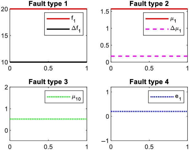
. Under this condition, the aerostat is only pushed forward along the x-axis. Four types of faults are set as follows: (1) Thrust offset:
 $\Delta {f_1} = {\rm{10N, }}{f_2} = \Delta {f_3} = \Delta {f_4} = {\rm{0}}$
; (2) Vectored angle offset:
 $\Delta {\mu _1} = \pi {\rm{/18}}$
,
 $\Delta {\mu _2} = \Delta {\mu _{\rm{3}}} = \Delta {\mu _{\rm{4}}} = {\rm{0}}$
; (3) Vectored angle stuck:
 ${\mu _{1{\rm{0}}}} = \pi {\rm{/6}}$
; (4) Thrust efficiency change:
 ${e_{\rm{1}}}{\rm{ = 0}}{\rm{.2, }}{e_{\rm{2}}}={e_{\rm{3}}}={e_{\rm{4}}}{\rm{ = 0}}$
.
In Fig. 3,
 $\Delta {f_{\rm{1}}}$
,
 $\Delta {\mu _{\rm{1}}}$
,
 $\Delta {\mu _{{\rm{10}}}}$
and
 ${e_{\rm{1}}}$
represent the single-type fault occurring independently to propeller 1.
Four single types of faults of propeller 1.

In Fig. 4,
 $\Delta {f_{{\rm{Hj}}}}$
and
 $\Delta {f_{{\rm{Vj}}}}$
,
 $j = 1 \cdots 4$
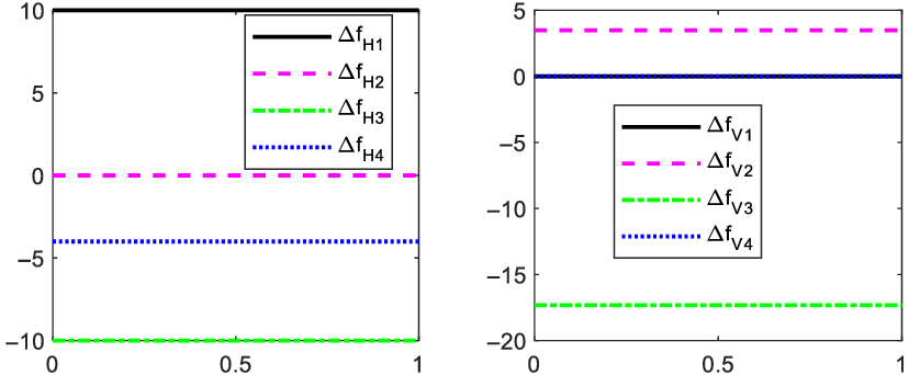
shows the change of indirect control force caused by j-type fault. The single thrust offset fault
 $\Delta {f_1}$
changes the horizontal indirect control force
 $\Delta {f_{{\rm{H1}}}}$
, but not the vertical indirect control force
 $\Delta {f_{{\rm{V1}}}}$
. By comparison, the single vectored angle offset
 $\Delta {\mu _1}$
changes the vertical indirect control force
 $\Delta {f_{{\rm{V2}}}}$
, but not the horizontal indirect control force
 $\Delta {f_{{\rm{H2}}}}$
. The reason is that the vertical indirect control force caused by the thrust offset
 $ - \Delta {f_i}\cos {\mu _i}$
and the horizontal indirect control force caused by vectored angle offset
 ${f_i}\cos {\mu _i}\Delta {\mu _i}$
are related to the previous coefficient
 $\cos {\mu _i}$
. At this point,
 ${\mu _1} = \pi {\rm{/2}}$
, and thus
 $\cos {\mu _i}{\rm{ = 0}}$
. The horizontal and vertical indirect control forces
 $\Delta {f_{{\rm{H3}}}}$
and
 $\Delta {f_{{\rm{V3}}}}$
change due to the vectored angle stuck
 ${\mu _{1{\rm{0}}}}$
. Meanwhile, failure of the thrust efficiency loss
 ${e_{\rm{1}}}{\rm{ = 0}}{\rm{.2}}$
changes the horizontal indirect control
 $\Delta {f_{{\rm{H4}}}}$
, which is related to the magnitude of initial thrust and vectored angle as shown in Equations (7) and (8).
Results of single-type faults on indirect control force.

In Fig. 5,
 $\Delta {f_{xj}}$
,
 $\Delta {f_{yj}}$
,
 $\Delta {f_{zj}}$
, and
 $\Delta {f_{\psi j}}$
,
 $j = 1 \cdots 4$
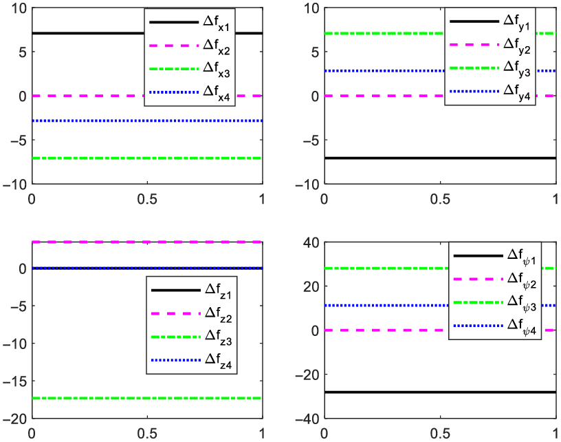
show the change of direct control quantity caused by j-type fault. The single thrust offset
 $\Delta {f_1}$
changes the direct control forces
 $\Delta {f_{x1}}$
,
 $\Delta {f_{y1}}$
, and
 $\Delta {f_{\psi 1}}$
at the same time; single vectored angle offset
 $\Delta {\mu _1}$
changes the direct control force
 $\Delta {f_{z{\rm{2}}}}$
; single vectored angle stuck
 ${\mu _{1{\rm{0}}}}$
changes the direct control forces
 $\Delta {f_{x{\rm{3}}}}$
,
 $\Delta {f_{y{\rm{3}}}}$
,
 $\Delta {f_{z{\rm{3}}}}$
, and
 $\Delta {f_{\psi {\rm{3}}}}$
together; single thrust efficiency loss
 ${e_{\rm{1}}}{\rm{ = 0}}{\rm{.2}}$
changes the direct control force
 $\Delta {f_{x{\rm{4}}}}$
,
 $\Delta {f_{y{\rm{4}}}}$
, and
 $\Delta {f_{\psi {\rm{4}}}}$
together. Given the constant distribution matrix
 ${\bf{T}}$
, the relationship between the changes of indirect and direct control forces is a constant multiple.
Results of single fault on direct control.

3.2 Multi-type faults synthesis
One vectored propeller can have many types of faults at the same time. However, a comprehensive fault cannot be regarded as the superposition of individual ones, given their coupling. Rather, the total can be expressed by the difference between the fault-free and faulted control forces as
 \begin{align}\begin{array}{l}f_{_{iH}}^f = f_{_{iH}}^r - f_{_{iH}}^n\\[5pt] f_{_{iV}}^f=f_{_{iV}}^r - f_{_{iV}}^n\end{array}\end{align}
where
 $f_{_{iH}}^f$
,
 $f_{_{iV}}^f$
(
 $i = 1 \ldots 8$
) represent the change of propeller i in the fault indirect control force. If the vectored angle is stuck, then the vectored angle offset is not considered and they are modeled separately. If the thrust offset, efficiency loss, and vectored angle offset occur at the same time, then the fault indirect control forces are
 \begin{align}\left\{ \begin{array}{l}f_{_{iH}}^r = (1 - {e_i})({f_i}+\Delta {f_i})\sin\! ({\mu _i} + \Delta {\mu _i})=f_{_{iH}}^n - {e_i}f_{_{iH}}^n+(1 - {e_i})({f_i}{\rm{cos}}\ {\mu _i}\Delta {\mu _i} + \sin {\mu _i}\Delta {f_i})\\[5pt] f_{_{iV}}^r = - (1 - {e_i})({f_i}+\Delta {f_i})\cos\!({\mu _i} + \Delta {\mu _i}) = f_{_{iV}}^n - {e_i}f_{_{iV}}^n+(1 - {e_i})({f_i}{\rm{sin}}\ {\mu _i}\Delta {\mu _i} - \cos {\mu _i}\Delta {f_i})\end{array} \right.\end{align}
Meanwhile, the fault indirect control forces caused by non-stuck combined faults are
 \begin{align}\begin{array}{l}f_{_{iH}}^f= - {e_i}f_{_{iH}}^n+(1 - {e_i})({f_i}{\rm{cos}}\ {\mu _i}\Delta {\mu _i} + \sin {\mu _i}\Delta {f_i})\\[5pt] f_{_{iV}}^f= - {e_i}f_{_{iV}}^n+(1 - {e_i})({f_i}{\rm{sin}}\ {\mu _i}\Delta {\mu _i} - \cos {\mu _i}\Delta {f_i})\end{array}\end{align}
When the vectored angle stuck, thrust offset, and efficiency loss occur together, the fault indirect control forces are
 \begin{align}\left\{ \begin{array}{l}f_{_{iH}}^r = (1 - e_i^{})({f_i}+\Delta {f_i})\sin {\mu _{i0}}=f_{_{iH}}^n+(1 - e_i^{})({f_i}+\Delta {f_i})\sin {\mu _{i0}} - {f_i}\sin {\mu _i}\\[5pt]f_{_{iV}}^r = - (1 - e_i^{})({f_i}+\Delta {f_i})\cos {\mu _{i0}}=f_{_{iV}}^n+{f_i}\cos {\mu _i} - (1 - e_i^{})({f_i}+\Delta {f_i})\cos {\mu _{i0}}\end{array} \right.\end{align}
while the fault indirect control forces caused by stuck combined ones are
 \begin{align}\begin{array}{l}f_{_{iH}}^f=(1 - e_i^{})({f_i}+\Delta {f_i})\sin {\mu _{i0}} - {f_i}\sin {\mu _i}\\[5pt]f_{_{iV}}^f={f_i}\cos {\mu _i} - (1 - e_i^{})({f_i}+\Delta {f_i})\cos {\mu _{i0}}\end{array}\end{align}
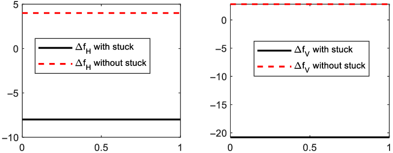
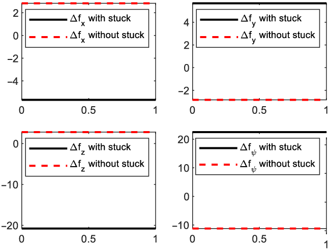
Furthermore, taking propeller 1 as an example, the influences of combined faults on indirect and direct control forces are studied when four faults occur in one propeller at the same time. The faults are divided into stuck and non-stuck according to different fault models.
Figures 6 and 7 show that the combined faults cause the fault indirect and direct control forces of all channels.
Change of indirect control forces caused by combined faults.

Change of direct control forces caused by combined faults.

4. Fault identification and controller design
4.1 Actuator fault modeling and fault estimation
The dynamic model Equation (2) of the aerostat with faults can be written as
 \begin{align}{\bf{M}}{{{\dot{\bf X}}}_{\rm{r}}} &= {{\bf{F}}_{{\bf{GB}}}}+{{\bf{F}}_{\bf{A}}}+{{\bf{F}}_{\bf{I}}}+{\bf{F}}_{_{\bf{T}}}^{\rm{r}}\nonumber \\[5pt] &={{\bf{F}}_{{\bf{GB}}}}+{{\bf{F}}_{\bf{A}}}+{{\bf{F}}_{\bf{I}}}+{\bf{ F}}_{_{\bf{T}}}^{\bf{n}}+{\bf{ F}}_{_{\bf{T}}}^{\bf{f}}\end{align}
where
 ${\bf{F}}_{_{\bf{T}}}^{\rm{r}}$
refers to the actual direct control force with faults,
 ${\bf{F}}_{_{\bf{T}}}^{\bf{n}}$
is the nominal direct control force without faults, and
 ${\bf{F}}_{_{\bf{T}}}^{\rm{f}}$
is the direct control force generated by faults.
 ${\bf{F}}_{_{\bf{T}}}^{\rm{f}}$
is divided into two forms, with stuck and non-stuck faults, as shown in Equations (11) and (13), respectively.
The fault force described in Equation (11) shows the non-stuck case, that is, the actuator has only thrust and deflection offsets and no efficiency loss. The fault dynamics model Equation (14) can be rewritten as
 \begin{align}{{{\dot{\bf X}}}_{\rm{r}}}&={{\bf{M}}^{{\bf{ - 1}}}}{\bf{\Big(}}{{\bf{F}}_{{\bf{GB}}}}+{{\bf{F}}_{\bf{A}}}+{{\bf{F}}_{\bf{I}}}+{\bf{Tf}}_{_{{\bf{HV}}}}^{\bf{n}}+{\bf{ Tf}}_{_{{\bf{HV}}}}^{\bf{f}}{\bf{\Big)}}\nonumber \\[5pt]&={{\bf{M}}^{{\bf{ - 1}}}}{\bf{\Big(}}{{\bf{F}}_{{\bf{GB}}}}+{{\bf{F}}_{\bf{A}}}+{{\bf{F}}_{\bf{I}}}+{\bf{ Tf}}_{_{{\bf{HV}}}}^{\bf{n}}{\bf{\Big)}} + TS\Big[\boldsymbol\Delta {\textbf{f}}_{{\bf{i}}}^{}{\boldsymbol{\Delta \mu }}_{{\bf{i}}}^{}{{\bf{\Big]}}^{\rm{T}}}\end{align}
where
 \begin{align}{\bf{F}}_{_{\bf{T}}}^{\rm{f}}={\bf{ Tf}}_{_{{\bf{H}}{\rm{V}}}}^{\bf{f}}{\bf{ = TS}}\left[ \begin{array}{l}{\boldsymbol{\Delta}{\bf f}}_{_{\bf{i}}}^{}\\[5pt]{\bf{\Delta \unicode{x03BC} }}_{_{\bf{i}}}^{}\end{array} \right]\end{align}
and
 ${\boldsymbol{\Delta}{\bf f}}_{_{\bf{i}}}^{}{\rm{ = [}}\begin{array}{*{20}{@{}c@{}}}{\Delta f_{_1}^{}}\;\;\;\; {\Delta f_2^{}}\;\;\;\; {\Delta f_3^{}}\;\;\;\; {\Delta f_{_4}^{}}\end{array}{\rm{]}}$
,
 ${\bf{\Delta \unicode{x03BC} }}_{_{\bf{i}}}^{}{\rm{ = [}}\begin{array}{*{20}{@{}c@{}}}{\Delta \mu _{_1}^{}}\;\;\;\; {\Delta \mu _2^{}}\;\;\;\; {\Delta \mu _3^{}}\;\;\;\; {\Delta \mu _{_4}^{}}\end{array}{\rm{]}}$
. We define
 ${\bf{S}} = [{{\bf{S}}_{\bf{f}}},{{\bf{S}}_{\bf{\unicode{x03BC} }}}]$
, where
 \begin{align*}{{\bf{S}}_f} = \left[ {\begin{array}{*{20}{c@{\quad}c@{\quad}c@{\quad}c}}{{\rm{sin}}\ {\mu _1}}& {} &{} &{}\\[5pt]{}& {{\rm{sin}}{\mu _2}}& {}& {}\\[5pt]{}& {}& {{\rm{sin}}{\mu _3}}& {}\\[5pt]{}& {}& {}& {{\rm{sin}}{\mu _4}}\\[5pt]{ - \cos {\mu _1}}& {}& {} &{}\\[5pt]{}& { - \cos {\mu _2}} &{}& {}\\[5pt]{}& {}& { - \cos {\mu _3}} &{}\\[5pt]{} &{}& {} &{ - \cos {\mu _4}}\end{array}} \right],{{\bf{S}}_{\bf{\mu }}} = \left[ {\begin{array}{*{20}{c@{\quad}c@{\quad}c@{\quad}c}}{{{\rm{f}}_{\rm{1}}}{\rm{cos}}\ {\mu _1}}& {} &{} &{}\\[5pt]{}& {{{\rm{f}}_2}{\rm{cos}}{\mu _2}}& {}& {}\\[5pt]{}& {}& {{{\rm{f}}_3}{\rm{cos}}{\mu _3}} &{}\\[5pt]{}& {}& {}& {{{\rm{f}}_4}{\rm{cos}}{\mu _4}}\\[5pt]{{{\rm{f}}_4}{\rm{sin}}\ {\mu _1}}& {}& {}& {}\\[5pt]{}& {{{\rm{f}}_4}{\rm{sin}}{\mu _2}}& {} &{}\\[5pt]{} &{}& {{{\rm{f}}_4}{\rm{sin}}{\mu _3}}& {}\\[5pt]{}& {}& {}& {{{\rm{f}}_4}{\rm{sin}}{\mu _4}}\end{array}} \right],\end{align*}
For the real state of the aerostat with fault
 ${{\bf{X}}_{\rm{r}}}$
, combined with the dynamic models (2) and (15) without and with fault, respectively, the theoretical representation of actuator offset fault is
 \begin{align}{{\bf{[\boldsymbol\Delta f}}_{_{\bf{i}}}^{}{\bf{\Delta \unicode{x03BC} }}_{_{\bf{i}}}^{}{\bf{]}}^{\rm{T}}}={({\bf{TS}})^{{\bf{ - 1}}}}{\bf{M}}{{\dot{\bf X}}_{\rm{r}}} - {({\bf{TS}})^{{\bf{ - 1}}}}{\bf{M}}{\dot{\bf X}}\end{align}
Assuming that the aerostat acceleration can be measured and other model parameters can be obtained, then the theoretical offsets can be calculated using Equation (17). However, given the redundant actuator configuration, the dimension of allocation matrix
 ${\bf{T}}$
is 4 × 8, and thus the fault model in Equation (17) is underdetermined and have countless solutions. With the aim to obtain a unique fault solution, four each of independent and free variables in Equation (17) should be designed. In actual cases, if the free variables are determined by sensor measurement, then the independent variables have a unique solution. Considering the vectored propeller, the vectored angle offsets can be measured more accurately than thrust offset, so vectored angle offsets are designed as measurable free variables. Then the following filter is used to estimate the thrust offset according to
 \begin{align}\left\{ \begin{array}{l}{\dot{\hat{\bf{d}}}} = - {\bf{P}}{\hat{\bf{d}}} + {\bf Pd}\\[5pt]{\bf{d}} = {\boldsymbol\Delta}{\bf f}_{_{\bf{i}}}^{}={({\bf{T}}{{\bf{S}}_{\rm{f}}})^{{\bf{ - 1}}}}{\bf{M}}{{{\dot{\bf X}}}_{\rm{r}}} - {({\bf{T}}{{\bf{S}}_{\rm{f}}})^{{\bf{ - 1}}}}{\bf{M}}{\dot{\bf X}}\end{array} \right.\end{align}
where
 ${\bf{P}}$
is a diagonal coefficient matrix with all positive variables. Set
 ${{\bf{e}}_{\bf{d}}}={\hat{\bf d}} - {\bf d}$
, then
 \begin{align}{{\dot{\bf e}}_{\bf{d}}} = {\dot{\hat{\bf{d}}}} - \dot{\bf d} = {\bf -P}{\hat{\bf d}} + {\bf Pd} = {\bf -P}{{\bf{e}}_{\bf{d}}}\end{align}
Thus, the Hurwitz condition is satisfied, the fault estimation error gradually approaches zero. Then the actuator fault identification and fault force estimation results are
 \begin{align}{\boldsymbol{\Delta}} {\hat{\bf f}}_{_{\bf{i}}}^{}={\hat{\bf{d}}}\end{align}
 \begin{align}{\bf{D}} = {\bf TS}{\bf \Big[}\boldsymbol\Delta {\hat{\bf f}}_{_{\bf{i}}}^{}{\boldsymbol{\Delta}} {\tilde{\bf \unicode{x03BC} }}_{_{\bf{i}}}^{}{{\bf{\Big]}}^{\rm{T}}}\end{align}
where
 ${\boldsymbol{\Delta}} {\tilde{\bf \unicode{x03BC} }}_{_{\bf{i}}}^{}$
is the vectored angle offset measured by the sensors.
4.2 Fault-tolerant tracking control and fault compensation
4.2.1 General structure and controller design
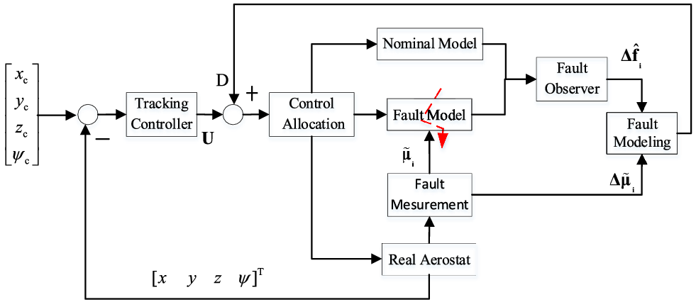
Figure 8 shows the general structure of tracking control based on actuator fault estimation. The design consists of five modules: tracking controller, control allocation, fault observer, fault measurement and fault modeling. The design principle of the fault observer is given above in Section 4.1, and output is the thrust offset. The fault model unit is a sensor system for vectored angle measurement and calculates the fault force in the body coordinate system according to the results of fault identification and measurement. The fault force is added to the controller for compensation. The control receives and allocates the total control force to multiple actuators to finish the tracking task.
General controller structure.

The current state is
 $P(x,y,z,\psi )$
, and the expected state is
 ${P_c}({x_c},{y_c},{z_c},{\psi _c})$
. The desired tracking acceleration
 ${\dot u_d},{\dot v_d},{\dot w_d},{\dot r_d}$
in inertial frame is given by PID controllers, as
 \begin{align}\begin{array}{l}{{\dot u}_d} = {k_{pu}}({x_c} - x) + {k_{du}}({{\dot x}_c} - \dot x) + {k_{iu}}\int\!{({x_c} - x)dt} \\[5pt]{{\dot v}_d} = {k_{pv}}({y_c} - y) + {k_{dv}}({{\dot y}_c} - \dot y) + {k_{iv}}\int \!{({y_c} - y)dt} \\[5pt]{{\dot w}_d} = {k_{pw}}({z_c} - z) + {k_{dw}}({{\dot z}_c} - \dot z) + {k_{iw}}\int \!{({z_c} - z)dt} \\[5pt]{{\dot r}_d} = {k_{pr}}({\psi _c} - \psi ) + {k_{dr}}({{\dot \psi }_c} - \dot \psi ) + {k_{ir}}\int \!{({\psi _c} - \psi )dt} \end{array}\end{align}
As the yaw is coupled with the position control, the commanded yaw angle is defined as
 ${\psi _c} = {\rm{atan2}}({y_c} - y,{x_c} - x)$
or fixed to certain direction. The commanded inertial acceleration must be transformed into the body fixed frame for control force calculation, as
 \begin{align}{\bf{U}} = {\bf{M}}{{\bf{J}}^{{\rm{ - 1}}}}{{\bf{[}}\begin{array}{*{20}{c}}{{{\dot u}_d}}\;\;\;\; {{{\dot v}_d}}\;\;\;\; {{{\dot w}_d}}\;\;\;\; {{{\dot r}_d}}\end{array}{\bf{]}}^{\rm{T}}}\end{align}
4.2.2 Control allocation based on pseudo-inverse
The dynamic inverse is used to calculate the indirect action forces
 ${{\bf{f}}_{{\bf{HV}}}}$
from direct ones
 ${{\bf{F}}_{\bf{T}}}$
, which can be derived from the position controller described in Section A. Thus,
 \begin{align}{{\bf{F}}_{\bf{T}}}{\bf{ = U + D}}\end{align}
 \begin{align}{{\bf{f}}_{{\bf{HV}}}} = pinv({\bf{T}}){{\bf{F}}_{\bf{T}}}\end{align}
where
 $pinv({\bf{T}})$
is the pseudo-inverse matrix of
 ${\bf{T}}$
. The choice of the control matrix
 ${\bf{T}}$
is highly important in dynamic inverse control allocation to avoid a singular value. Here, the indirect action forces
 ${{\bf{f}}_{{\bf{HV}}}}$
are introduced, resulting in a constant control matrix
 ${\bf{T}}$
. Thus, the inverse matrix is also a constant, that is, a solution is always available in the control allocation. The control variables of each thruster can be deduced from Equation (3).
 \begin{align}\begin{array}{l}{f_i} = \sqrt {f_{iH}^2 + f_{iV}^2} \\[5pt]{\mu _i} = a\tan 2\left( {{f_{iH}}, - {f_{iV}}} \right).\end{array}\end{align}
Assuming that the forces and deflection angles are controllable, then the desired action force
 ${{\bf{F}}_{\bf{T}}}$
for position or attitude tracking can be obtained.
4.2.3 Simulation results
Position tracking is given for validating the controller. The aerostat at initial state is
 ${P_{}}({\rm{0}}, {\rm{0}}, {\rm{0}}, {\rm{0}})$
, and the tracking target state is
 ${P_c}(\!- 20, - 10,30,0)$
. The identification and tracking results are validated by setting the faults to change with time in a series situations.
 \begin{align*}\left\{ \begin{array}{l}{\boldsymbol{\Delta}{\bf f}}_{_{\bf{i}}}^{}{\rm{ = [}}\begin{array}{*{20}{c}}{\rm{3}}\;\;\;\; {\rm{1}}\;\;\;\; { - {\rm{5}}}\;\;\;\; { - {\rm{4}}},\end{array}{\rm{]}},\quad {\bf{\Delta \unicode{x03BC} }}_{_{\bf{i}}}^{}{\rm{ = [}}\begin{array}{*{20}{c}}{\rm{0}}\;\;\;\; {\rm{0}}\;\;\;\; {\rm{0}}\;\;\;\; {\rm{0}}\end{array}{\rm{] }}\quad (0 \le t \lt {\rm{5}}0)\\[5pt]{\boldsymbol{\Delta}{\bf f}}_{_{\bf{i}}}^{}{\rm{ = [}}\begin{array}{*{20}{c}}{\rm{0}}\;\;\;\; { - {\rm{2}}}\;\;\;\; { - {\rm{2}}}\;\;\;\; {\rm{3}}\end{array}{\rm{]}},\quad {\bf{\Delta \unicode{x03BC} }}_{_{\bf{i}}}^{}{\rm{ = [}}\begin{array}{*{20}{c}}{{\rm{0}}{\rm{.3}}}\;\;\;\; {\rm{0}}\;\;\;\; {{\rm{0}}{\rm{.2}}}\;\;\;\; { - {\rm{0}}{\rm{.2}}}\end{array}{\rm{] }}\quad ({\rm{5}}0 \le t \lt {\rm{10}}0)\\[5pt]{\boldsymbol{\Delta}{\bf f}}_{_{\bf{i}}}^{}{\rm{ = [}}\begin{array}{*{20}{c}}2\;\;\;\; {\rm{0}}\;\;\;\; 0\;\;\;\; 1\end{array}{\rm{]}},\quad {\bf{\Delta \unicode{x03BC} }}_{_{\bf{i}}}^{}{\rm{ = [}}\begin{array}{*{20}{c}}{{\rm{0}}{\rm{.1}}}\;\;\;\; { - {\rm{0}}{\rm{.2}}}\;\;\;\; { - {\rm{0}}{\rm{.1}}}\;\;\;\; { - {\rm{0}}{\rm{.1}}}\end{array}{\rm{] }}\quad ({\rm{10}}0 \le t \lt {\rm{20}}0)\end{array} \right.,\end{align*}
The fault observer parameters are set as
 \begin{align*}{\bf{P}} = diag(\,{p_1},{p_2},{p_3},{p_4}) = diag({\rm{0}}.1,{\rm{0}}.1,{\rm{0}}.1,{\rm{0}}.1),\end{align*}
and the controller parameters for trajectory tacking are chosen as
 \begin{align*}\begin{array}{l}{{\bf{k}}_{\bf{p}}} = diag\!\left( {{k_{pu}},{k_{pv}},{k_{pw}},{k_{pr}}} \right)=diag\!\left( {0.{\rm{1}},0.{\rm{1}},0.0{\rm{5}},{\rm{1}}} \right)\\[5pt]{{\bf{k}}_{\bf{i}}} = diag\!\left( {{k_{iu}},{k_{iv}},{k_{iw}},{k_{ir}}} \right)=diag\!\left( {0.0,0.0,0.0,0.0{\rm{5}}} \right)\\[5pt]{{\bf{k}}_{\bf{d}}} = diag\!\left( {{k_{iu}},{k_{iv}},{k_{iw}},{k_{ir}}} \right)=diag\!\left( {{\rm{1}},{\rm{1}},{\rm{1}},{\rm{2}}} \right)\end{array}\end{align*}
Simulation results are presented below.
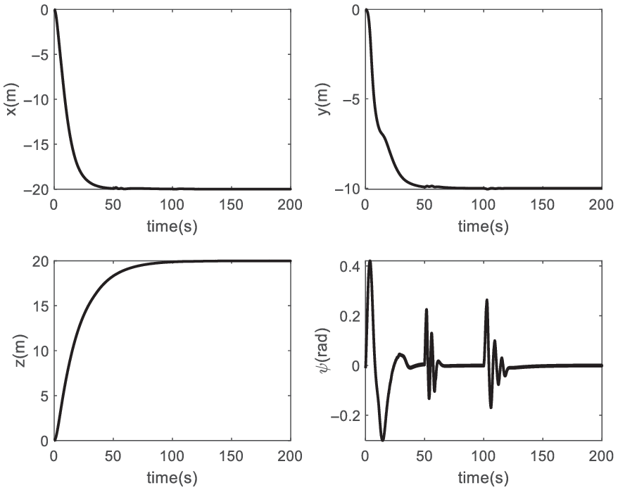
Figure 9 shows the tracking results as the faults step change at 50 s and 100 s. The yaw angle clearly oscillated in the case of the actuator fault switched at 50 s and 100 s. While fault influences are depressed in position tracking, altitude tracking shows slight fluctuations in altitude tracking.
State tracking result of the controller.

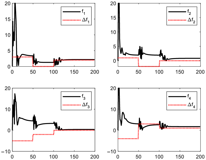
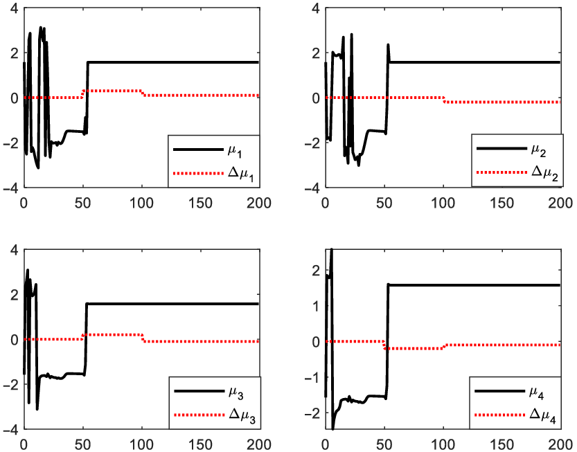
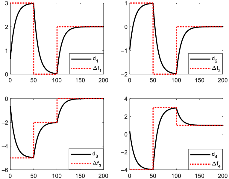
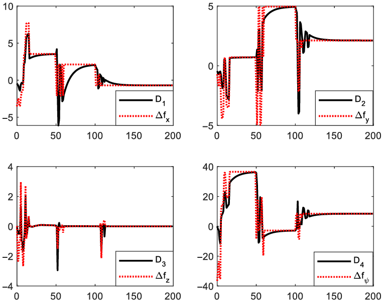
Figures 10 and 11 show the control outputs for tracking and actuator faults. Figures 12 and 13 show the actuator fault identification and fault force estimation, where
 $\Delta {f_{\rm{1}}}$
,
 $\Delta {f_{\rm{2}}}$
,
 $\Delta {f_{\rm{3}}}$
, and
 $\Delta {f_{\rm{4}}}$
are the theoretical values of actuator faults;
 ${{\rm{d}}_{\rm{1}}}$
,
 ${{\rm{d}}_{\rm{2}}}$
,
 ${{\rm{d}}_{\rm{3}}}$
, and
 ${{\rm{d}}_{\rm{4}}}$
are the identified values of actuator faults;
 $\Delta {f_x}$
,
 $\Delta {f_y}$
,
 $\Delta {f_z}$
, and
 $\Delta {f_\psi }$
are the theoretical values of fault direct control force; and
 ${{\rm{D}}_{\rm{1}}}$
,
 ${{\rm{D}}_{\rm{2}}}$
,
 ${{\rm{D}}_{\rm{3}}}$
, and
 ${{\rm{D}}_{\rm{4}}}$
are the estimated values of fault direct control forces. The actuator faults change in steps. Switch time in identification shows a transition, and the stable and theoretical values is consistent with those shown in Fig. 12. The model-based output fault force estimation effectively tracks the time-varying fault force, as shown in Fig. 13.
Real thrust output and offset.

Real vectored angle output and offset.

Thrust offset identification and theoretical value.

Fault forces estimation and theoretical value.

In the tracking controller design, the actuator fault is chosen directly as the identification variable instead of fault force, which is nonlinear time-varying in tracking, as shown in Fig. 13. The fault force coefficient matrix
 ${\bf{S}}$
in Equation (16) is a trigonometric function of vectored angle, which changes rapidly in tracking and thus difficult to identify accurately. However, in real cases, actuator fault (thrust offset) is constant or slowly time-varying, and thus can be identified accurately by the linear fault observer in Equation (18). Moreover, the nonlinear time-varying fault force is easier to deduce from the fault model in Equation (21).
5. Conclusions
This study presents a fault-tolerant tracking control strategy for a multi-vectored propeller airship with actuator faults. The proposed method uses an observer to identify actuator faults and calculate the fault force by modeling. Virtual control is the tracking control compensated with the estimated fault force. Given the redundant actuator configuration, the vectored angle offset is selected as the free fault variable obtained from measurement and the thrust offset is the independent fault variable determined by identification. For accurate identification, the thrust offset is chosen as the identified variable and the nonlinear time-varying fault force is deduced by nonlinear fault model. Simulation results show satisfactory tracking that accommodates different types of actuator faults. In addition, the real actuator faults are given directly.
The robustness of this fault diagnosis is vulnerable to the accuracy of system modeling, because the identification in this method relies on the measurement of acceleration difference of faulty aerostat with the ideal model. However, given its large volume that is lighter than air, the aerostat is highly influenced by wind or other disturbances. For accurate identification and estimation, the other effects on acceleration should be eliminated, and more models or measures can be adopted to suppress the influence of such disturbances. In this study, only a non-stuck and no efficiency loss situations are considered. Further research can be based on the full model and solve the nonlinear fault identification.
Acknowledgements
This work was supported by the National Natural Science Foundation of China (Nos. 52175103, 61733017), Foundation of State Key Laboratory of Robotics of China (No. 2018O13), and Shanghai Pujiang Program (No. 18PJD018).