1. INTRODUCTION
The integration of Inertial Navigation System (INS) and Global Positioning System (GPS) architectures can be achieved through the use of many time-domain filters, such as extended Kalman, unscented Kalman, divided difference, and particle filters. The main objective of these filters is to achieve precise fusion of the data from GPS and INS to provide INS-only navigation solution during GPS outages. The prediction mode performance of all state-of-the-art time-domain filters is poor with significant drift in the INS-only solution. Typically, the integration of an INS with GPS is commonly achieved through the use of an Extended Kalman filter (EKF). However, several shortcomings of the EKF-based INS/GPS integration schemes have recently been reported (Julier and Uhlmann, Reference Julier and Uhlmann1997; Kong, Reference Kong2000; Shin, Reference Shin2005). To overcome these limitations many researchers have proposed derivativeless-based filters for state vector estimation. Examples of those filters include unscented Kalman filter (UKF) (Julier and Uhlmann, Reference Julier and Uhlmann1997; Kong, Reference Kong2000; Shin, Reference Shin2005), divided difference filter (DDF) (Nørgaard et al., Reference Nørgaard, Poulsen and Ravn2000a; van der Merwe et al., Reference van der Merwe, Wan and Julier2004), and particle filter (PF) (Azimi-Sadjadi, Reference Azimi-Sadjadi2001; Nordlund and Gustafsson, Reference Nordlund and Gustafsson2001). UKF and DDF require less computational effort than PF for the same level of accuracy (van der Merwe et al., Reference van der Merwe, Wan and Julier2004). The main objective of all the above filters is to provide accurate INS-only navigation solutions during GPS outages. In fact, the INS-only navigation solution from all these filters, when run in the prediction mode, still cannot detect and recover the long-term motion dynamics that affect the overall INS/GPS system performance during GPS outages.
To improve the prediction mode of the filters applied in the INS/GPS integration solution, many bridging models have been proposed. A simple mathematical algorithm was proposed by Nassar and Schwarz (Reference Nassar and Schwarz2002). It calculates the difference between the INS and GPS positions at the beginning and at the end of the outage. The resulting difference is attributed to a time square error. The choice of this simple error model resulted from an analysis of the INS error model for short-time periods up to a few minutes. Recently, many neural network (NN) structures have extensively been applied in INS/GPS integration during GPS outages. For example, Chiang et al. (Reference Chiang, Noureldin and El-Sheimy2003) proposed the direct feed-forward NN to provide INS/GPS integration solution during GPS outages. Subsequently, Noureldin et al. (Reference Noureldin, Osman and El-Sheimy2004) integrated the NN with wavelet multi-resolution analysis to estimate the navigation solution during GPS outages and concluded that it is better than the standalone NN. Semeniuk and Noureldin (Reference Semeniuk and Noureldin2006) applied the radial basis NN to improve the INS-only solution. Abd-Elhamid et al. (Reference Abd-Elhamid, Noureldin and El-Sheimy2007) combined fuzzy logic with NN. Most recently, Chiang et al. (Reference Chiang, Noureldin and El-Sheimy2008) applied the constructive NN. All these methodologies were applied using the INS data as input to the NN to obtain the difference between GPS and INS as output.
In this paper an alternative frequency-domain method is developed and investigated. The frequency-domain method is more suitable than time-domain methods when studying dynamic systems because their behaviour is usually frequency dependent in a specific frequency band. The frequency band of interest of the INS/GPS system is determined by the GPS system only (upper bound is 0·5 Hz if GPS data are collected at 1 Hz sampling rate). Any other frequency band may not be considered for two reasons:
• the INS system can effectively recover the high frequency dynamic motion in this band in which INS data always exist,
• the motion signals of INS in the frequency band above 0·5 Hz are noisy and may degrade the time-domain solution.
If we have an INS/GPS system with GPS sampling rate at 1 Hz, the data bandwidth from the fundamental frequency (controlled by the length of the data sequence) to 0·5 Hz (Nyquist frequency) can be used to develop the transfer function in the frequency domain and subsequently the impulse response in the time-domain for bridging GPS outages. Then, the long-term INS/GPS motion dynamics can be recovered from the INS-only solution using the developed impulse response model.
The transfer function of the INS/GPS system is developed in the frequency-domain using the single input, single output dynamic system concept and then it is transformed into the time-domain to obtain the impulse response equivalent. Working in the time-domain, the input to the dynamic system is the INS-only solution and the output is the INS/GPS integration solution. Our focus is the estimation of velocity by convolving the derived impulse response model with the INS-only solution during GPS outages. Subsequently, numerical integration of the velocity provides the corresponding position solution. The significance of this paper is that it develops a bridging methodology for GPS outages in the frequency domain, which results in a new, rigorous, and physically meaningful model.
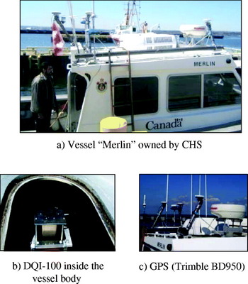
To examine the performance of the new bridging model, kinematic data from a dual frequency Trimble BD950 GPS receiver and inertial data from a tactical-grade IMU (DQI-100) are collected onboard a hydrographic surveying vessel owned by the Canadian Hydrographic Service (CHS). We use the UKF on the collected data to study the performance of the impulse response model, and the improvement of the INS/GPS system navigation solution. We also compare our proposed frequency-dependent INS/GPS impulse response model with the traditional time-domain feed-forward neural network (FFNN) to further investigate the validity of the proposed method.
2. CURRENT STATE-OF-THE-ART BRIDGING MODELS FOR GPS OUTAGES
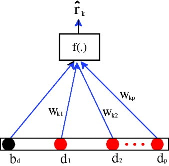
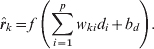
The artificial neural network (ANN) has recently been introduced as a powerful tool for signal modelling and system identification in time domain. Most commonly, ANNs have been used in INS/GPS integration to bridge GPS outages. What follows is a brief explanation of the fundamentals of the ANN and the most common architecture used in INS/GPS integration literature namely, the feed-forward neural network (FFNN). More details can be found in Haykin, (Reference Haykin1999). An artificial neural network can simply be interpreted as a highly nonlinear autoregressive model, which is constructed by a network of fundamental elements, namely the neurons that are usually developed from nonlinear functions, called activation functions. Human neurons are cells that make up the brain but ANN neurons are mathematical models that receive weighted input vectors and feed-through nonlinear functions (activation functions) that generate the neurons on output. Therefore, an ANN neuron can be considered as a mathematical model that can simulate the brain cell functions that respond almost identically to similar inputs. Figure 1 shows the block diagram of a simple neuron, where d i represents one variable in the input layer, f is the activation function,  represents the output variable, b d is the bias associated with the input layer, and w ki represent the neural network unknown weights (very similar to the unknown coefficients of the well-known autoregressive model but we call it weights in the ANN method).
Simple neuron structure.

The simple model of a neuron  k in Figure 1 can be represented in the compact form as (Haykin, Reference Haykin1999):
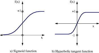
Therefore, the neurons and consequently the ANN that contains many neurons, have a nonlinear form in which the activation functions f can be chosen arbitrarily. Activation functions are nonlinear functions, which are used in the mathematical model of ANN neurons to provide a highly nonlinear ANN model. The choice of the activation function can change the behaviour of the ANN network considerably. Figure 2 shows two of the most commonly used activation functions in an ANN, namely the sigmoid and the hyperbolic tangent function.
Activation functions – sigmoid and hyperbolic tangent functions.

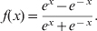
For example, the hyperbolic tangent function for any variable x, which represents  in Equation (2), is given by the following equation:
The first disadvantage of ANN is that the selection of the activation function is arbitrary and it is determined by trial-and-error to provide the least mean square error for a specific application. This renders the method sub-optimal, because of the arbitrary character of the activation function.
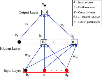
An ANN can be developed in many different ways, depending on the network architecture. For example, one such ANN architecture is the feed-forward neural network (FFNN). More specifically, the FFNN architecture is currently being considered as the state-of-the-art method to bridge GPS outages in time-domain solutions (see Chiang et al. (Reference Chiang, Noureldin and El-Sheimy2003); Kaygisiz et al. (Reference Kaygisiz, Erkmen and Erkmen2004) ; Jwo and Huang, (Reference Jwo and Huang2004); Chiang et al. (Reference Chiang, Noureldin and El-Sheimy2006); Wang et al., Reference Wang, Wang, Sinclair and Watts2006; Kaygisiz et al. (Reference Kaygısız, Erkmen and Erkmen2007) ). The FFNN is an interconnection of layers (vectors) in which data and calculations flow in a single direction, from the input layer (vector) to hidden layer(s) (vector(s)) and then the output layer (vector). A multi-input, single-output FFNN is characterised by one input layer (vector of input values), one output layer (one output value), and one or more hidden layers (vector of intermediate neurons) (Haykin, Reference Haykin1999). A hidden layer is considered as an intermediate layer between the input and output layers and introduces additional nonlinearity to the FFNN. The multi-input, single-output FFNN is implemented in our study as a benchmark method against which our proposed impulse response model will be tested and validated. Figure 3 shows an example of a fully connected three-layer FFNN. The input vector of variables d is activated by a nonlinear activation function f k that provides hidden neurons h in a hidden layer. Then, the resulting hidden neurons are activated by another activation function f to produce the network output  . The number of hidden layers and hidden neurons is also chosen arbitrarily; the more hidden layers, and the more neurons, the lower the mean-square error. Clearly, the FFNN design is based on many arbitrary selected variables rendering the approach non-rigorous and sub-optimal for system identification.
Multi-input single-output feed-forward Neural Network structure (p: input variables; s: neurons, and one output variable) – blue arrows indicate the weights of the connected layers.

The FFNN output is computed as (Haykin, Reference Haykin1999):

where, wd→h are free unknown FFNN weights, which connect the input layer with the hidden layer, wh→r are free unknown FFNN weights, which connect the hidden layer with the output layer, b d is an unknown bias term associated with the input layer, and b h is another unknown bias term associated with the hidden layer. The FFNN unknown weights and biases (wd→h, wh→r, b d and b h) are estimated through a tuning (training) procedure. Assuming that r d is the output of the process (i.e., desired output) and the corresponding network output is estimated from Equation (3) then, the FFNN tuning (training) stage can be used to minimise the following error function (Nørgaard et al., Reference Nørgaard, Ravn, Poulsen and Hansen2000b; Haykin Reference Haykin1999):

Tuning (training) the FFNN is accomplished through iterative adjustments of the FFNN unknown weights and biases until the best FFNN architecture is achieved:
• the best length of input layer (subscript i in Equation 3),
• the best length of hidden neurons (subscript k in Equation 3.), and
• the best values of FFNN unknown weights and biases (wd→h, wh→r, b d and d h).
The best FFNN architecture is a model that provides the least mean-square-error that is determined from the estimated FFNN output and the actual (desired) output (trial-and-error methodology). There exist various tuning (training) algorithms, which are fundamental to the design of neural networks. The Levenberg-Marquardt tuning (training) algorithm is the most widely used in FFNN, which we implement in this paper (see Haykin, Reference Haykin1999 and Nørgaard et al., Reference Nørgaard, Ravn, Poulsen and Hansen2000b for more details).
It should be noted that because the number of the input layer variables and the number of hidden layer neurons are defined by trial and error, the FFNN-based time-domain solution for bridging GPS outages (also, for any other application) is suboptimal and non-rigorous. In addition, the selection of the frequency band of interest is not considered in the FFNN-based time-domain solution. Therefore, a rigorous and optimal frequency-domain solution is proposed in the following section (no trial and error approach is employed to determine the proposed frequency-domain model).
3. DEVELOPMENT OF INS/GPS IMPUSLE RESPONSE MODEL
In this section, we explain a new frequency-dependent rigorous INS/GPS impulse response method in four steps that is applied in the bridging of GPS outages in an INS/GPS solution. In this method, the input is the INS-only navigation solution and the output is the INS/GPS navigation solution. The frequency-domain model structure is single-input single-output system. The frequency band of interest is the frequency band of the GPS system in use (if the GPS sampling rate is one sample per second (1 Hz), the frequency band of interest is from the fundamental frequency to 0·5 Hz). We now proceed with the details of the development of the new and rigorous frequency-dependent INS/GPS impulse response model in four distinct steps:
3.1. Step 1: Least Squares Frequency Transform (LSFT)
The Least Squares Frequency Transform (LSFT) term is derived from the Least Squares Spectral Analysis (LSSA) method. The LSSA was first developed by Vaníček (Reference Vanícek1969) as an alternative to the classical Fourier methods to overcome all their inherent limitations. It provides many advantages (Pagiatakis, Reference Pagiatakis1999) but most notably unequally spaced data series can easily be transformed to the frequency domain without prior interpolation or re-sampling; unequally spaced series are very common in an INS/GPS system. An observed time series is considered to be represented by d=d(t 1), d(t 2),…,d(t n). The main objective of the LSSA is to extract periodic signals from d, especially when d contains both random and systematic noise. Thus, we can set up a model g to represent d that can be expressed as follows:

where Φ is a matrix of known base functions and x is the vector of unknown parameters. To estimate the model parameters x, the standard least-squares method is applied (Mikhail, Reference Mikhail1976; Vaníček and Krakiwsky, Reference Vanícek and Krakiwsky1986; Pagiatakis, Reference Pagiatakis1999), in which the difference between g and d becomes minimum. In LSFT we search for periodic signals that are expressed in terms of sine and cosine base functions. So, if we specify the form of the base functions to be trigonometric on a set of spectral angular frequencies ωi, i=1, 2,…,m, we have:

Let  and Φ=[cos(ωit), sin(ωit)], then
 can be determined by using the standard least-squares technique. The amplitudes and phases of the waves as functions of frequency can be estimated as follows:
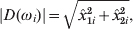
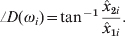
The covariance matrix of  is also propagated through Equations (7) and (8) to provide the corresponding covariance matrix for |D(ω)i| and ∠D(ωi). This is the first step towards the least squares spectral analysis that looks further into Equations (7) and (8) to estimate significant spectral peaks and make inferences about the spectral content of the time series under investigation (Pagiatakis, Reference Pagiatakis1999). However, in an INS/GPS integrated system used for hydrographic surveys for example, we collect raw data from which we obtain a series of INS/GPS integrated navigation and INS-only navigation solutions using UKF. These series are treated as single-input single-output system, in which the INS-only navigation solution is introduced as an input to the system and the INS/GPS integrated navigation solution is the output. We need to determine the amplitudes and phases of all waves (at all discrete angular frequencies ωi within the band of interest) as defined by Equations (7) and (8). These amplitudes and phases are used to estimate the transfer function of the dynamic system. Thus, we call this step Least Squares Frequency Transform (LSFT) rather than Least Squares Spectral Analysis (LSSA).
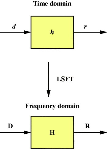
Consider a linear dynamic system with input and output as shown in Figure 1 (upper box). The LSFT is used to transform the input vector d and output vector r from the discrete time-domain to the frequency domain to provide input vector D and output vector R as shown in Figure 4 (lower box).
Time-domain and LSFT-based frequency-domain representation of a single input/single output system.

The system frequency response, or transfer function H(ωi) is a complex function that can be represented in the form of modulus (magnitude) |H(ωi)| and argument (phase angle) ∠H(ωi) as follows (Pintelon and Schoukens, Reference Pintelon and Schoukens2001):
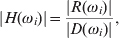

where ωi are all discrete angular frequencies in the band of interest. In this study we also propagate the covariance matrices of D(ωi) and R(ωi) to derive the covariance matrices of |H(ωi)| and ∠H(ωi). Propagating the errors of the observations to the estimated complex response (complex transfer function) of the dynamic system is not the usual practice of dynamic system response modelling.
3.2. Step 2: Parzen Spectral Window Smoothing (PSWS)
In the frequency domain, the INS/GPS system transfer function |H(ωi)| usually contains unexpected and sudden spikes (artifacts), which have no physical meaning. These spikes normally arise from the frequency response analysis of discrete (discretisation of real analogue data set) input/output data sets. The PSWS is employed here to estimate a smooth system transfer function. The Parzen spectral window takes the form (Buttkus, Reference Buttkus2000):

where M=2/f 0, f 0 is the frequency lag, x=πMdf i/2, and df i=f i−f c is the frequency increment between the centre frequency of the spectral window (f c) and the frequency (f i) at which W(df i) is estimated. The smooth transfer function |H(ωi)|s can be estimated as the average of all (discrete) magnitudes of |H(ωi)| within the Parzen spectral window range±f 0, using W(df i) as weights.
3.3. Step 3: Inverse Least Squares Frequency Transform (ILSFT)
In this step we transform |H(ωi)|s from the (discrete) frequency domain to the (discrete) time domain thus, obtaining the impulse response  of the INS/GPS system, where τi is time lag. This transformation is achieved via the ILSFT (Craymer, Reference Craymer1998). The ILSFT can be estimated using the following formula in matrix form:

The associated covariance matrix of |H(ωi)|s is propagated through Equation (12) to provide the corresponding covariance matrix of  .
3.4. Step 4: Convolution in time-domain
Once the impulse response  is estimated, the time-domain convolution of any INS input with provides the predicted INS/GPS output. For example, in this research during the GPS outages, the convolution of the INS-only solution with the estimated impulse response provides the predicted INS/GPS solution. Therefore, the impulse response function can be seen as an activation function in an ANN, with the important distinction that the impulse response is a physically meaningful model developed rigorously from the frequency-dependent method, and from the frequency band of interest (fundamental frequency to the GPS Nyquist frequency) when GPS signals are blocked to recover the long-term dynamic, whereas in the case of an ANN the activation function is arbitrarily selected and subsequently forced (i.e., “trained”) to fit the data.
The above four steps show that the development of the system dynamics in the frequency domain can provide the optimal and rigorous solution and no trial-and-error approach is applied to determine the model structure (optimal model based on single-input single-output system). The frequency response method produces a physically meaningful model within the frequency band of interest (rigorous frequency-dependent model based on the GPS system frequency band to simulate the GPS influence when GPS signals are denied). The following section shows the results of both, the FFNN-based time-domain solution and the Impulse-Response-based frequency-domain solution.
4. FIELD SYSTEM TEST
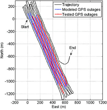
To examine the performance of the proposed methodology, dual frequency GPS data from a Trimble BD950 receiver and inertial data from DQI-100 IMU (see Table 1) are collected in Hamilton Harbour, Ontario, onboard hydrographic surveying vessel “Merlin” owned by the Canadian Hydrographic Service of the Department of Fisheries and Oceans. Figure 5 shows the vessel configuration. The test trajectory with eight artificial outages (each of 300 s length – blue and red lines) is shown in Figure 6.
Field system used to collect the kinematic data used in this study.

Test trajectory showing the four data segments (blue) used to develop the dynamic response model and the four artificial GPS outages (red) used to test the model.

DQI-100 IMU specifications (BEI, 2002).

5. RESULTS AND DISCUSSION
At the beginning, the integrated navigation solution from the loosely coupled INS/GPS system is obtained using the UKF estimator. In the UKF, we use 22 inertial states (three states each of: position, velocity, gyro bias, accelerometer bias, gyro scale, and accelerometer scale errors, as well as four quaternion states to express the attitude) to develop the INS system state-space equations. Along with the state-space equations, we use GPS positions and velocities, and estimated INS positions and velocities to develop the INS/GPS system observation equations. In parallel, the impulse responses for positions and velocities, respectively, are developed to update the UKF during GPS outages. The INS/GPS and INS-only navigation solutions for the four segments # 1, 3, 5, and 7 (blue lines in Figure 6 from start to end direction) are used to develop the impulse response of the INS/GPS system following the four steps outlined in Section 3. Then, the other four GPS segments # 2, 4, 6, and 8 (red lines in Figure 6 from start to end direction) are used as artificial outages to examine the performance of the developed impulse response model.
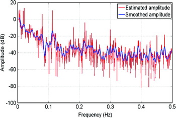
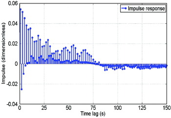
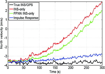
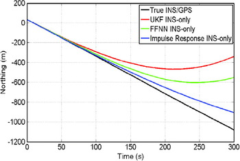
Figures 7 and 8 show how the impulse response model is developed for north velocity using data segment #5 (300 s long). Figure 7 shows the INS/GPS system transfer function estimated from Step 1 (red line, cf. Section 3) and the corresponding smoothed INS/GPS system transfer function (blue line) estimated from Step 2 using Parzen spectral window smoothing with a length of 161 peak amplitudes in total (frequency lag f 0=2/T=0·00667 Hz in Equation 11). Figure 8 shows the impulse response estimated from Step 3. This impulse response is then applied on the INS-only data of segment #6 (treated as artificial outage of 300 s) for which the full INS/GPS solution is available (see Figures 9 and 10). It should be noted that the impulse response model solution for INS/GPS velocity (Figure 9) is estimated using convolution in the time-domain (cf. Step 4). However, the corresponding INS/GPS position solution (Figure 10) is estimated using the integration of the INS/GPS velocity solution in the navigation frame. It is clear that most of the long-term motion dynamics of the DQI-100 IMU are recovered successfully for velocity and position solutions.
Estimated (red) and smoothed (blue) transfer function for north velocity developed from INS and INS/GPS data of segment #5.

INS/GPS impulse response model for the north velocity of segment #5.

North velocity: UKF INS/GPS (black), UKF INS-only (red), FFNN INS-only (green), and Impulse Response INS-only (blue) comparison for segment #6.

North position: UKF INS/GPS (black), UKF INS-only (red), FFNN INS-only (green), and Impulse Response INS-only (blue) comparison for segment #6.

To further examine the performance of the proposed methodology, the FFNN is adopted using the windowing technique because the focus of this paper is to use the bridging model for an online (real-time) solution (not post-processing). The online multi-input single-output architecture used herein is similar to the windowed method followed by Semeniuk and Noureldin (Reference Semeniuk and Noureldin2006). The input layer ranges from 25 to 50 variables, and contains the current and previous INS-only solutions. The hidden layer ranges from 5 to 10 neurons, and the output layer contains one variable describing the difference between the INS/GPS solution and the INS-only solution. The lengths of input and hidden vectors are defined by trial and error as mentioned before based on the minimum mean square error that makes FFNN solution a suboptimal solution. The INS/GPS and INS-only navigation solutions for the four segments # 1, 3, 5, and 7 (blue lines in Figure 6 from start to end direction) are used to develop the FFNN model of the INS/GPS system following the methodology outlined in Section 4. Then, the other four artificial GPS outages # 2, 4, 6, and 8 (red lines in Figure 6 from start to end direction) are used to examine the performance of the developed FFNN model. Again, Figures 9 and 10 show an example of the FFNN INS-only solution that is tested on artificial outage # 6 (300 s long) for which the full INS/GPS solution is available. It is shown that the impulse response INS-only solution outperforms the UKF INS-only solution and FFNN INS-only solution. Other outages show very similar behaviour and they are not shown here.
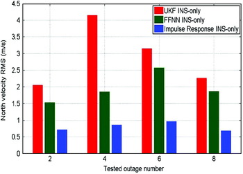
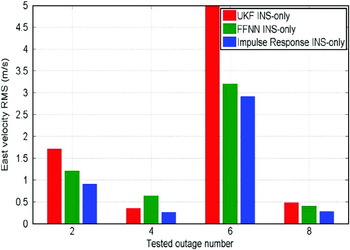
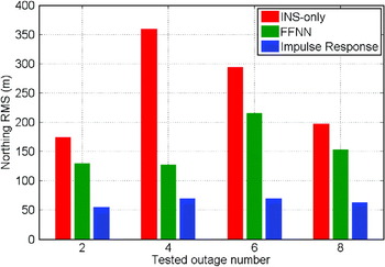
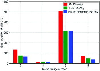
Now, three root mean square (RMS) errors are calculated from three estimated INS-only navigation solutions (namely UKF prediction, the FFNN model, and Impulse Response model) and the desired INS/GPS navigation solution. The three RMS errors are estimated for the north and east velocities and positions for the four GPS artificial outages (# 2, 4, 6, and 8). Figures 11 and 12 show the RMS errors for north and east velocities, whereas Figures 13 and 14 show the RMS errors for northing and easting solutions. It is clear that the impulse response INS-only solution outperforms the UKF INS-only solution and FFNN INS-only solution in all cases.
North velocity RMS for tested GPS outages # 2, 4, 6, and 8.

East velocity RMS for tested GPS outages # 2, 4, 6, and 8.

Northing RMS for tested GPS outages # 2, 4, 6, and 8.

East position RMS for tested GPS outages # 2, 4, 6, and 8.

Finally, both, the estimated RMS of the INS-only solution (RMS INS) and the estimated RMS of the system response (RMS IR) solutions are compared with the true values (from INS/GPS) to provide the percentage of dynamic recovery using the frequency-dependent impulse response model solution (PDR IR) as follows:

The PDR IR from Equation (13) is used to measure the level of improvement that the impulse response model added to the INS-only solution during GPS outages. The overall (average) PDR IR using the impulse response model from the four tested GPS outages (# 2, 4, 6, and 8) is 72%, 42%, 75%, and 40% for north velocities, east velocities, northing, and easting, respectively when compared with the INS-only solution in the UKF prediction mode. Similarly, the corresponding PDR FFNN is used to measure the level of improvement that the FFNN model adds to the INS-only solution during GPS outages. The overall (average) PDR FFNNof the four tested GPS outages (# 2, 4, 6, and 8) is 33%, 28%, 39%, and 37% for north velocities, east velocities, northing, and easting, respectively, when compared with INS-only solution in the UKF prediction mode. These results show clearly that the impulse response model can effectively be used to detect and recover the long-term motion dynamics of DQI-100 IMU during 300 s GPS outages when compared with the UKF INS-only and the FFNN INS-only solutions. Also, the difference between the estimated overall (average) two-dimensional (2D) velocities and positions RMS errors corresponding to the impulse response model and the FFNN, respectively, shows that the frequency-dependent INS/GPS system impulse response model can improve the INS-only solution, when GPS outages exist, by about 26% for 2D velocities and positions when compared with the current state-of-the-art time-domain INS/GPS FFNN model.
6. CONCLUSION
The frequency-dependent INS/GPS system impulse response model for bridging GPS outages was developed in this paper. The impulse response model can efficiently be used to detect and recover the long-term motion dynamics of DQI-100 IMU during 300 s GPS outages with success rate of about 72%, 42%, 75%, and 40% for north velocities, east velocities, northing, and easting, respectively when compared with the INS-only solution. Also, a comparison was carried out between the traditional time-domain feed-forward neural network (FFNN) model and the proposed impulse response model. It is concluded that the frequency-dependent, impulse response INS/GPS system can improve the INS-only solution, when GPS outages exist, by about 26% for 2D velocities and positions when compared with the current state-of-the-art time-domain INS/GPS FFNN model.
ACKNOWLEDGMENTS
This research was partially supported by the GEOIDE National Centre of Excellence (Canada) and by the Natural Sciences and Engineering Research Council (NSERC) of Canada. The authors would like to acknowledge the Canadian Hydrographic Service (CHS) for providing access to vessel “Merlin” and their help with the kinematic test.