Introduction
The high energy density (energy stored per unit mass and volume) of rechargeable lithium-ion (Li-ion) batteries has transformed portable electronics over the last two decades. Such batteries are the technology of choice for the electrification of transport and are expected to find application in static electricity storage, especially in grid distribution networks. Intensive research efforts worldwide are being devoted to the realization of new generations of Li-ion batteries to address these markets. While this work is important, the best that can be achieved is a doubling of energy density compared with the Li-ion batteries of today. A twofold increase in energy density is insufficient for the long-term demands of transport and electricity storage; for example, it is unlikely to deliver a +300 mile driving range between chargings, which would transform electric vehicles. Achieving a step-change in energy storage requires an investigation of technologies that differs from Li-ion based systems. In this article, we consider two lithium battery technologies, lithium-air (Li-air) and lithium-sulfur (Li-S), that could theoretically deliver the transformation in performance required in the long-term. The reactions at the cathode (positive electrode) in Li-air and Li-S cells involve the reversible reduction of O2 and S, respectively, and are fundamentally different from those in Li-ion cells. Neither of these technologies is an established commercial product, and both present significant challenges, including, in particular, materials challenges in order to realize practical devices. In this article, we will begin by considering the energy that can be stored in Li-air and Li-S batteries, and then examine each technology, in turn, highlighting the challenges that must be addressed in transforming these batteries from theory to practice. Several recent reviews on Li-air and Li-S are available.Reference Girishkumar, McCloskey, Luntz, Swanson and Wilcke1–Reference Lee, Kim, Cao, Choi, Liu, Lee and Cho4 A third battery technology, zinc-air, will not be considered here but has been reviewed recently.Reference Lee, Kim, Cao, Choi, Liu, Lee and Cho4
Energy storage of lithium-air and lithium-sulfur batteries
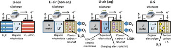
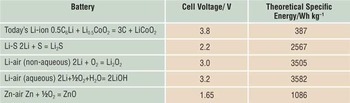
The theoretical energy density of a battery is based on the overall cell reaction. The values for Li-air and Li-S are given in Table I, along with the corresponding values for a typical Li-ion cell and rechargeable Zn-air. Schematic representations of the Li-ion, Li-air (based on aqueous and non-aqueous electrolytes), and Li-S cells are shown in Figure 1.
Schematic representation of non-aqueous and aqueous Li-air as well as Li-S cells. LISICON, lithium superionic conductor.

Theoretical energy storage for several batteries based on their cell reactions.

In the Li-ion cell, Li is removed from an intercalation cathode, for example LiCoO2, on charging and is inserted between sheets of carbon atoms in the graphite negative electrode; discharge reverses this process. In the Li-air cell, the intercalation cathode of the Li-ion cell is replaced by a porous, electronically conducting substrate, usually carbon, flooded with the electrolyte. Upon discharge, Li-ions form by oxidation of the lithium metal anode and pass across the electrolyte. At the cathode, oxygen from the atmosphere dissolves in the electrolyte within the pores and is reduced. In the case of the non-aqueous Li-air cell, reduced oxygen combines with Li+ ions from the electrolyte to form Li2O2, (2Li++O2+2e– ↔ Li2O2), and the process is reversed on charging.Reference Abraham and Jiang5–Reference Ogasawara, Débart, Holzapfel, Novák and Bruce7 The Li-air cell is, in fact, a Li-O2 cell, but the use of the terminology “air” for such electrodes is now so ingrained that we adopt it here. For the aqueous Li-air battery, water is also involved in the discharge reaction to form LiOH (2Li++½O2+H2O+2e–↔2LiOH). Hence, this cell is often called a Li-water battery.Reference Visco, Katz, Nimon and DeJonghe8 In the discharge of the Li-S cell, the sulfur at the cathode is reduced and combines with Li+ to ultimately form Li2S (2Li+ + 2e– + S ↔ Li2S) (see the next section on Li-S cells). The reaction is reversed on charge.
The energy storage of the Li-air cell is sometimes given as the specific energy based on the mass of Li alone (11,586 Wh kg–1); however, as the cell discharges, oxygen from the atmosphere continuously enters the cathode, resulting in an increase in mass, so that the mass of O2 should be included in the determination of specific energy. The step change in energy storage on migrating from Li-ion to Li-air and Li-S, apparent in Table I, is due to two factors. First, the amount of Li stored per unit mass and unit volume in Li2O2, LiOH, and Li2S, is greater than that in LiCoO2. Second, graphite with a maximum Li content of C6Li is replaced with the higher energy density Li metal; although this brings its own problems, as discussed later.
So far, we have considered only the theoretical energy densities based on the cell reactions. Unfortunately, the overhead involved in translating such theoretical values into practical energy storage is greater for Li-S and Li-air than for Li-ion cells. The cathode must be a porous conducting matrix within which Li2S, Li2O2, or LiOH forms, and the anode must consist of excess Li metal to compensate for its inefficiency in cycling. Typically, the theoretical to practical energy density conversion yield for a battery is 20–45%, depending upon the battery system involved. Accordingly, practical specific energies >1000 Wh kg–1 have been predicted for fully developed Li-air batteries; however, this figure must be treated with considerable caution at the present time. A practical battery with energy density > 500 Wh Kg–1 is sufficient to deliver a +300 mile driving range. Note that the gain in volumetric energy density over Li-ion is less than for specific energy. Depending on applications, one or both may be important.
Li-air batteries
Aqueous and non-aqueous Li-air batteries were first described by ViscoReference Visco, Katz, Nimon and DeJonghe8 and Abraham,Reference Abraham and Jiang5, Reference Laoire, Mukerjee, Plichta, Hendrickson and Abraham6 respectively. Although both cells involve O2 reduction, the differences between aqueous and non-aqueous Li-air are significant enough to merit description in separate sections.
The non-aqueous Li-air battery
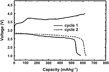
The solid Li2O2 that accumulates in the pores of the porous carbon cathode on discharge is oxidized on charge. There is an unusually large separation between charge and discharge voltages, even at low charging/discharging rates, Figure 2.
First discharge/charge cycle of a Li-O2 battery with Co-Pc catalyzed carbon as the cathode (from References Reference Abraham and Jiang5 and Reference Laoire, Mukerjee, Plichta, Hendrickson and Abraham6).

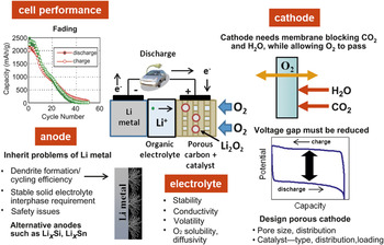
Such a voltage separation leads to inefficiencies in energy storage, even though the columbic efficiency (charge in/charge out) may be close to 100%. Various catalysts have been added to the electrode in an attempt to reduce the voltage separation and thus increase energy efficiency, as well as sustain cycling.Reference Abraham and Jiang5, Reference Ogasawara, Débart, Holzapfel, Novák and Bruce7, Reference Débart, Paterson, Bao and Bruce9, Reference Lu, Gasteiger, Crumlin, McGuire and Shao-Horn10 The mechanism by which these might operate and the selection of optimized materials is something of considerable interest and represents an important materials challenge. The influence of the organic electrolyte on oxygen reduction and subsequent oxidation of the reduced products has been studied.Reference Ogasawara, Débart, Holzapfel, Novák and Bruce7, Reference Laoire, Mukerjee, Abraham, Plichta and Hendrickson11, Reference Laoire, Mukerjee, Abraham, Plichta and Hendrickson12 Recent reports demonstrate that organic carbonate–based electrolytes, used widely in studies of Li-air to date, lead to electrolyte decomposition on discharge rather than Li2O2 formation, so some early results may need revision.Reference Mizuno, Nakanishi, Kotani, Yokoishi and Iba13–Reference Zhang, Xu and Liu17 The voltage separation is by no means the only problem facing the non-aqueous Li-air battery; the challenges are summarized in Figure 3. The porous substrate within which the Li2O2 forms must be a good conductor and in practice of low cost, hence the dominance of carbon.Reference Zhang, Zheng, Liang, Zhang, Wang, Hendrickson and Plichta18–Reference Yang, He and Xia19, Reference Xu, Xiao, Wang, Zhang and Zhang20 Although high surface areas are, in principle, an advantage, the consequent small pores may easily become blocked by Li2O2 before becoming completely filled, thus limiting discharge capacity. Pores that are too large may compromise rate and rechargeability because of their low surface area. It is anticipated that pore sizes in the region of 10–200 nm are likely to be optimal. Good wetting of the pore surfaces by the electrolyte is important, as is a high pore volume.Reference Read21, Reference Read, Mutolo, Ervin, Behl, Wolfenstine, Driedger and Foster22 If a catalyst is used, then controlling its size, morphology, and distribution within the pores are key challenges.Reference Débart, Paterson, Bao and Bruce9 The rate capability of the cell on discharge depends on the O2 solubility and its diffusion in the electrolyte to the electrode surface. It has also been shown that as a film of insulating Li2O2 grows on the electrode surface, it will slow the rate and soon passivate the electrode.Reference Girishkumar, McCloskey, Luntz, Swanson and Wilcke16 In addition, the electrolyte must be inert to strong nucleophiles such as O2–.
Challenges facing the non-aqueous Li-air battery.

Identifying electrolyte materials that satisfy all the requirements of solubility, wettability, and stability is a formidable challenge. If the cell is to operate in ambient air, then ingress of CO2 and H2O must be avoided by protecting the cathode with a membrane that blocks these species, allowing only O2 to enter the cell.Reference Zhang, Xu and Liu23
Developing a practical lithium metal anode has been a challenge for more than 30 years.Reference Abraham, Brummer and Gabano24 On charging, dendrites of lithium grow out from the electrode and, at worst, can cause short circuits or, at best, loss of lithium. The strongly reducing nature of Li metal results in a reaction with the electrolyte, forming a stabilizing solid electrolyte interphase (SEI) layer. However, on cycling, the continuous re-formation of the SEI layer consumes charge. As a result, cycling efficiency of the Li electrode usually is low, in the 97–98% range, whereas efficiencies exceeding 99.98% are required for practical cells with 1000 or more cycles.Reference Kummer and Weber34 If lithium metal is to be used, either an excess has to be employed to compensate for lithium metal loss, which compromises energy storage, or the lithium metal anode must be protected by, for example, a solid electrolyte such as LISICON, (LIthium SuperIonic CONductor) (e.g., Li(1+x+y)AlxTi(2–x)SiyP(3–y)O12).Reference Visco, Katz, Nimon and DeJonghe8 Alternatively, the lithium metal could be replaced by Si or Sn, which may be pre-lithiated or lithiated in situ.
The aqueous Li-air battery
Since lithium reacts violently with water, the aqueous Li-air battery only functions because the lithium anode is protected from the aqueous electrolyte by a lithium conducting solid electrolyte barrier, similar to that described for the non-aqueous Li-air cell. This innovation by Visco made the Li-water cell a reality.Reference Visco, Katz, Nimon and DeJonghe8 Of course, ensuring efficient cycling of the Li/solid electrolyte interphase is itself a challenge. A thin film of a non-aqueous liquid or gel electrolyte is placed between the lithium metal and the ceramic ionic conductor in an effort to address this problem.Reference Imanishi, Hasegawa, Zhang, Hirano, Takeda and Yamamoto25–Reference Stevens, Toussaint, Caillon, Viaud, Vinatier, Cantau, Fichet, Sarrazindan and Mallouki28 The solid electrolyte/aqueous electrolyte interface suffers from corrosion, leading to increasing cell impedance.Reference Stevens, Toussaint, Caillon, Viaud, Vinatier, Cantau, Fichet, Sarrazindan and Mallouki28 In general, the Li-water battery faces many challenges similar to the non-aqueous Li-air battery for practical implementation.
One interesting approach, which has met with some success, is the introduction of a third (oxidation) electrode.Reference Stevens, Toussaint, Caillon, Viaud, Vinatier, Cantau, Fichet, Sarrazindan and Mallouki28 Because this third electrode does not become coated with solid LiOH, oxidation is more facile, involving oxidation of species in solution.Reference Stevens, Toussaint, Caillon, Viaud, Vinatier, Cantau, Fichet, Sarrazindan and Mallouki28
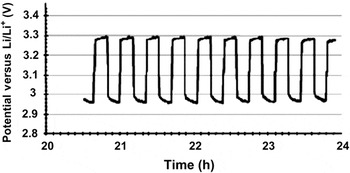
Small-scale Li-air cells have been fabricated in the laboratory and have been shown to sustain cycling (Figure 4). Although an attraction of the aqueous system is that, by definition, H2O does not have to be excluded from the cathode compartment of the cell, it is necessary to exclude CO2 to avoid formation of Li2CO3, instead of LiOH. Therefore, a membrane protecting the cathode by preventing CO2 ingress is required.
Performance of lab scale aqueous Li-air battery showing 10 complete discharge/charge cycles with a potential gap of ca. 0.3 V.Reference Stevens, Toussaint, Caillon, Viaud, Vinatier, Cantau, Fichet, Sarrazindan and Mallouki28

The lithium-sulfur battery
The concept of electrochemical energy conversion and storage utilizing sulfur as the positive electrode in an alkali metal anode battery dates back to at least the 1960s.Reference Herbert and Ulam29 Early Li-S batteries included both ambient and high-temperature versions.Reference Rauh, Abraham, Pearson, Surprenant and Brummer30, Reference Kaun, Nelson, Redey, Vissers and Henriksen31 They utilized elemental sulfur as the cathode active material contained in a porous electrode matrix, usually carbon. High-temperature batteries operating at ∼450°C employed Li-alloy anodes and LiCl-LiBr-KBr molten salt electrolytes,Reference Kaun, Nelson, Redey, Vissers and Henriksen31 whereas their room-temperature counterparts utilized elemental Li anodes in conjunction with organic electrolytes.Reference Rauh, Abraham, Pearson, Surprenant and Brummer30 Sodium-sulfur (Na-S) batteries operating at medium (∼130°C) to high (∼400°C) temperatures have also been developed with an anode consisting of metallic Na contained in a Na+ conducting ceramic tube such as β-Al2O3, which also serves as the separator in the battery.Reference Abraham, Rauh and Brummer32–Reference Kummer and Weber34
The electrochemical reduction of elemental S, which exists as S8 rings, to Li2S occurs through a series of intermediate lithium polysulfides of which the major phases are Li2S8, Li2S4, and Li2S2Reference Rauh, Shuker, Marston and Brummer35 (see discussion on Figure 7 later in text). The highly reduced Li2S2 and Li2S phases have high melting points, which necessitate the operation of the battery at high temperatures, up to 500°C, in order to facilitate good mass transport (molten salt based Li-sulfur) leading to high-capacity utilization of the sulfur electrode. Frequently, high internal resistance builds up due to the formation of insoluble products as the discharge proceeds in the battery, culminating in poor discharge efficiency and rechargeability. Although improved electrode design and high operating temperatures have partially overcome this weakness, the quest for Li-S batteries operating at ambient temperatures with very high capacities and rechargeability has continued.
In ambient-temperature Li-S batteries employing organic electrolytes, poor discharge capacities were a serious problem due to the precipitation of Li2S2 and Li2S in the cathode electrode pores and the consequential increase in the battery’s internal resistance and low discharge capacities due to poor S utilization. The use of solutions of lithium polysulfides (Li2Sn, where n = 8–10) in organic electrolytes was pursued to counter this.Reference Rauh, Abraham, Pearson, Surprenant and Brummer30 Lithium polysulfides are prepared by treating Li2S with an appropriate amount of elemental sulfur in an organic solvent. For example, to prepare Li2S8, a typical catholyte for ambient temperature Li-S cells, one mole of Li2S is stirred with seven moles of sulfur in a solvent such as tetrahydrofuran until all of the solid sulfur is converted to a solution of the lithium polysulfide (Equation 1):Reference Rauh, Shuker, Marston and Brummer35

The solubility of the polysulfides varies with the solvents used. Li2Sn, with n varying from 5 to 8, has been used to construct cells.Reference Rauh, Abraham, Pearson, Surprenant and Brummer30, Reference Rauh, Pearson and Brumner36 Because S is in a slightly reduced state as Sn 2–, there is a small sacrifice in the theoretical energy density. For example if n = 8, then a full reduction to Li2S (Equation 2) yields a capacity of 1.75e–/S instead of 2e–/S for the S/S2– couple:

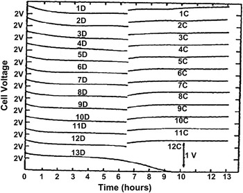
Figure 5 displays the discharge/charge cycling data for a Li-Li2S8 cell.Reference Rauh, Abraham, Pearson, Surprenant and Brummer30, Reference Rauh, Pearson and Brumner36 The cell discharges at an average 2V and charges at a slightly higher voltage. A unique feature of the charge half-cycle is the absence of an endpoint. An endpoint in the charging of a battery is usually indicated by an upward slope in the voltage at the end of charge, which is absent in the present case. This cell was completely discharged at the 13th discharge to calculate the average efficiency of cycling, found to be about 90%. This poor cycling efficiency is primarily attributed to self-discharge of the cell during charge, as indicated by the absence of an endpoint.
Galvanostatic cycling data for a Li/Li2Sn cell built with Li2S8 in tetrahydrofuran as the active material. The discharge and charge half cycles are identified on the curves. The total S concentration is about 5 M. Current density is 1 mA/cm2.Reference Rauh, Abraham, Pearson, Surprenant and Brummer30, Reference Rauh, Pearson and Brumner36

During charging of a Li-Li2Sn cell, the soluble Li2Sn diffuses to the Li anode through the porous separator and reacts with the Li anode to form insoluble Li2S2 and Li2S, which deposit on the Li anode surface. These reduced polysulfides react with the longer chain soluble Li2Sn, where n = 8–10, present in solution to form intermediate chain length soluble Li2Sn, which diffuse back to the positive electrode and are re-oxidized. This parasitic process takes place repeatedly, creating an internal ‘‘shuttle’’ phenomenon. It decreases the active mass utilization in the discharge process and markedly reduces the coulombic efficiency in the charge process. This is the reason for the absence of an endpoint for the charge half-cycle. Interestingly, the “shuttle” provides intrinsic overcharge tolerance for Li-S batteries, which is essential for all non-aqueous batteries, removing the need for electronic controls to balance individual cells and terminate their charging in a series-connected battery pack.
At the end of each of each discharge, the soluble polysulfides are reduced to Li2S2 and Li2S, which precipitate on the cathode. These insoluble agglomerates become electrochemically inaccessible over prolonged cycling, causing active mass loss and the build-up of impedance layers that result in cathode capacity fading. Capacity fading is also caused by the accumulation of a net amount of the insoluble Li2S and Li2S2 on the Li anode, which, in turn, seriously lowers its rechargeability.
Much of the research on the ambient temperature Li-S battery dealt with mitigating the self-discharge problem. The preceding discussion underscores the importance of immobilizing the Li2Sn to the cathode electrode to solve this problem. Among the avenues pursued are alternative electrolytes, particularly electrolytes based on organic oligomers, polymers and liquid electrolytes with reduced solubility for lithium polysulfides, Li+-ion conducting solid electrolytes to isolate the Li anode from the S cathode compartment to prevent reactions with Li, and improvements of the S cathode structure, including innovative architectures as described later.
Improving performance with electrolytes
Self-discharge and short cycle life have been impediments to full-fledged development of practical Li-S batteries with liquid electrolytes in organic solvents such as tetrahydrofuran,Reference Rauh, Abraham, Pearson, Surprenant and Brummer30 methyl acetate, and dioxolane.Reference Ryu, Ahn, Kim, Ahn, Cho, Nam, Kim and Cho37 Gel-like polymer electrolytes yielded good active mass utilization only at elevated temperature (90°C).Reference Chu38 Rechargeable cells incorporating a variety of polymer-containing electrolytes, including polyethylene oxide,Reference Shin and Cairns41 polyethylene glycol-dimethylether (PEGDME),Reference Yuan, Feng, Ai, Cao, Chen and Yang39, Reference Shin and Cairns41 and mixtures of PEGDME or tetraethylene glycol-dimethoxyethane with ionic liquidsReference Shin and Cairns41, Reference Shin and Cairns42 have shown longer cycle life and lower self-discharge. Pure ionic liquid electrolytes have also been utilized,Reference Yuan, Feng, Ai, Cao, Chen and Yang39, Reference Wang, Chew, Zhao, Ashraf, Wexler, Chen, Ng, Chou and Liu40 but these cells suffered rapid capacity fading. Aurbach et al.Reference Aurbach, Pollak, Elazari, Salitra, Kelley and Affinito43 revealed that the overall performance of Li-S cells can be greatly improved by introducing additives containing N–O bonds, for example LiNO3,Reference Aurbach, Pollak, Elazari, Salitra, Kelley and Affinito43 into the cell, leading to the creation of a protective film comprising LixNOy and/or LixSOy on the Li anode.
The use of Li+ conductive solid electrolytes to isolate the anode from the cathode to prevent self-discharge has been studied. One example is sulfide glasses such as Li2S–SiS2 and Li2S–P2S5.Reference Mercier, Malugani, Fahys and Robert44, Reference Pradel and Ribes45 Hayashi et al.Reference Hayashi, Ohtsubo, Ohtomo, Mizuno and Tatsumisago46 prepared a solid-state cell where the cathode (sulfur combined with copper) exhibits a stabilized discharge capacity of 650 mAh/g for 20 cycles. Visco and coworkersReference Visco and Chu47 proposed LISCONs such as lithium aluminum titanium phosphate to isolate the anode and cathode compartments and mitigate the S shuttle and self-discharge in Li-S cells.
Innovative cathode architectures
An interesting line of study involved the use of multiwall carbon nanotubes (MWCNTs) either as a MWCNT/S nano-composite with highly homogenous sulfur dispersionReference Zheng, Liu, Hu and Zhang48 or as a MWCNT-core/sulfur-shell structure.Reference Yuan, Yuan, Qiu, Chen and Zhu49 These latter cells have shown better cycling stability with capacity utilization of 670 mAh/g after 60 cycles.
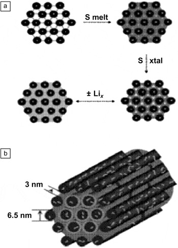
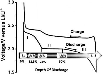
Carbon-sulfur composites comprised of high pore volume carbons with 3D-accessible channel nanostructures have shown promise for improved cell performance.Reference Ji, Lee and Nazar50 In these electrodes, sulfur is confined in the interconnected pore structure of mesoporous carbon, CMK-3 (Figure 6). The percentage of S mass is controlled to retain pathways for electrolyte/Li+ ingress and to accommodate the active mass volume expansion during cycling. The conductive carbon framework constrains the sulfur within its channels and generates essential electrical contact. Polymer modification of the carbon surface produces an electrode structure (Figure 6) that facilitates a more complete reaction by providing a chemical gradient to retard diffusion of the polysulfides into the electrolyte. Reversible S capacities up to 1320 mAh/g are reported with no shuttle phenomenon and 99.9% columbic efficiency on the first cycle. A typical cell cycle is illustrated in Figure 7, which also shows the various intermediate phases of S during the discharge. Capacity fading is reduced because of greatly reduced polysulfide concentration in the electrolyte, and the materials sustain reversible capacities of 1100 mAh/g for over 20 cycles.
(a) Schematic showing sulfur contained in interconnected pore structures of mesoporous carbon, CMK-3, and (b) PEG200 coated CMK-3/S composites.Reference Ji, Lee and Nazar50

The discharge and charge cycle of a Li-S cell with the CMK-3/S composite cathode.

Practical Li-S batteries
SION Power51 has developed a Li-S cell based on the soluble S chemistry, with a Li metal anode stabilized with protective surface coatings. The cell, packaged in a polymer pouch, has demonstrated 350 Wh/kg in unmanned aerial vehicles flights. This energy density is lower than the 500 Wh/kg they obtained in laboratory cells, which indicates the need for continued improvement of the packaging efficiency of this battery.
Summary and Future Prospects
The intense interest in Li-air and Li-S batteries at the present time testifies to the fact that there are very few approaches that offer a major leap forward in energy storage compared to Li-ion batteries. Although theoretically the energy densities of Li-air and Li-S cells are high, there are many challenges to be addressed on the path from theory to practice. As highlighted in the present article, such challenges are frequently rooted in materials discovery and optimization. Li-air and Li-S present rich opportunities for research; only by carrying out such research will it be possible to identify and then overcome the hurdles to practical devices. Future research should emphasize the development of high efficiency Li anodes for both Li-S and Li-air batteries through novel protected anode technologies and optimum electrolytes, better catalysts for the sustained cycling of the oxygen cathode, and appropriate battery packaging technologies. If the hurdles can be overcome, then the benefits for electrification of transport, static energy storage, and hence reduction in CO2 emissions would be transformational.