
Introduction
Lithium-ion battery (LIB) is the dominant technology for electrical energy storage in various applications such as portable electronics and electric vehicles. While unrivaled in their performance, the current LIBs are approaching their capacity limits of the intercalation compounds and there are also concerns about safety and the resource situation.[ Reference Manthiram 1 – Reference Yoo, Markevich, Salitra, Sharon and Aurbach 3 ] For example, concerns have been raised that the world's cobalt (Co) resources and reserves may not be sufficient to enable a global electromobility even when Co-poor next generation NMC materials (i.e., NMC 622 and 811) will be used.[ Reference Hamilton 4 ] All these reasons have led to an increasing interest in batteries based on alternative chemistries, which are not based on Li anymore and an increasing attention is focusing on new battery systems beyond lithium that possess higher energy density, consist of low-cost materials, and are safer and long lasting.
Magnesium battery
Mg battery has been proposed as an attractive candidate for future rechargeable batteries, mostly due to the high volumetric capacity of 3837 mAh/cm3 of the metal, which is significantly higher than that of lithium (2062 mAh/cm3) and sodium (1136 mAh/cm3).[ Reference Gregory, Hoffman and Winterton 5 ] It is worth noting that the volumetric energy density of a battery has to be considered particularly to control the size of battery packs for portable devices and vehicles. In contrast to Li or Na, Mg as a metallic anode has the nature of dendrite-free deposition.[ Reference Aurbach, Cohen and Meshkovich 6 , Reference Jäckle and Groß 7 ] Moreover, Mg has a reduction potential of −2.4 V versus SHE and can be safely handled in air. An important aspect of cost and sustainability is the high abundance of Mg element in the earth crust and its ready availability in various minerals all over the globe, e.g., as dolomite (CaCO3·MgCO3) or as magnesite (MgCO3).
Currently, the introduction of Mg batteries is impeded by several technical obstacles, such as the lack of an electrolyte, which is cost-effective, efficient, and chemically compatible with the electrode materials. In addition, the quest for practical cathodes offering high capacity and energy density is ongoing. So far, only a few types of conventional intercalation materials have been identified that are capable of storing Mg2+ ions reversibly.[ Reference Yoo, Shterenberg, Gofer, Gershinsky, Pour and Aurbach 8 – Reference Canepa, Sai Gautam, Hannah, Malik, Liu, Gallagher, Persson and Ceder 15 ] Thus, the challenges to realize the rechargeable Mg battery technology are not only the improvement of the electrolyte toward high oxidative stability, but also the discovery of cathode materials enabling high performance of Mg batteries.
General aspects of lithium–sulfur and magnesium–sulfur
Sulfur (S) is an attractive candidate for cathodes of the next-generation batteries owing to its high theoretical capacity of 1673 mAh/g, its natural abundance, non-toxicity, and low cost. When paired with a Li metal anode, the lithium–sulfur (Li–S) battery provides a high theoretical energy density of 2800 Wh/L and 2600 Wh/kg. Li–S battery has therefore been suggested as a promising high-energy post-Li-ion battery and extensively investigated in the past decade.[ Reference Manthiram, Fu, Chung, Zu and Su 16 , Reference Seh, Sun, Zhang and Cui 17 ] However, material issues are still to be solved for the commercialization of Li–S batteries such as the problems associated with the chemistry of S. Li metal anodes would have to be employed to ultimately achieve Li–S batteries with high-energy densities, but this would enhance the risk of dendrite growth. With a graphite anode, the theoretical energy density of the Li–S system drops from 2800 to 1100 Wh/L.
In contrast, Mg can be used as a metallic anode in Mg batteries, and the combination of Mg with S is therefore regarded as a promising electrochemical couple, too. The two-electron conversion reaction of Mg2+ + S + 2e− ↔ MgS yields a theoretical cell voltage of 1.77 V, thus offering a theoretical energy density of over 3200 Wh/L. Another aspect is that the reaction of a single Mg with S results in a volume expansion of 24%, while the active material expands by 72% when Li2S is formed.
Compared with the considerable technological advancements in Li–S batteries, the R&D of Mg–S battery is still in an early stage. The key challenge in the development of Mg batteries is to discover a suitable electrolyte, which is chemically compatible to the electrophilic S and capable of reversible Mg deposition/dissolution in a wide operating voltage range.
The research work on Mg batteries in general has been timely reviewed and thoroughly discussed,[ Reference Yoo, Shterenberg, Gofer, Gershinsky, Pour and Aurbach 8 – Reference Canepa, Sai Gautam, Hannah, Malik, Liu, Gallagher, Persson and Ceder 15 , Reference Muldoon, Bucur, Oliver, Sugimoto, Matsui, Kim, Allred, Zajicek and Kotani 18 – Reference Erickson, Markevich, Salitra, Sharon, Hirshberg, de la Llave, Shterenberg, Rozenman and Frimer 20 ] so that we will focus on the properties of Mg electrolytes in view of the application to S cathodes. Thereafter, we will illustrate the progress that is being made on Mg–S battery and discuss future prospects for high-energy Mg and Mg–S batteries.
Challenges and advances in the development of magnesium electrolytes
Organomagnesium-based electrolytes and the nucleophilicity problem
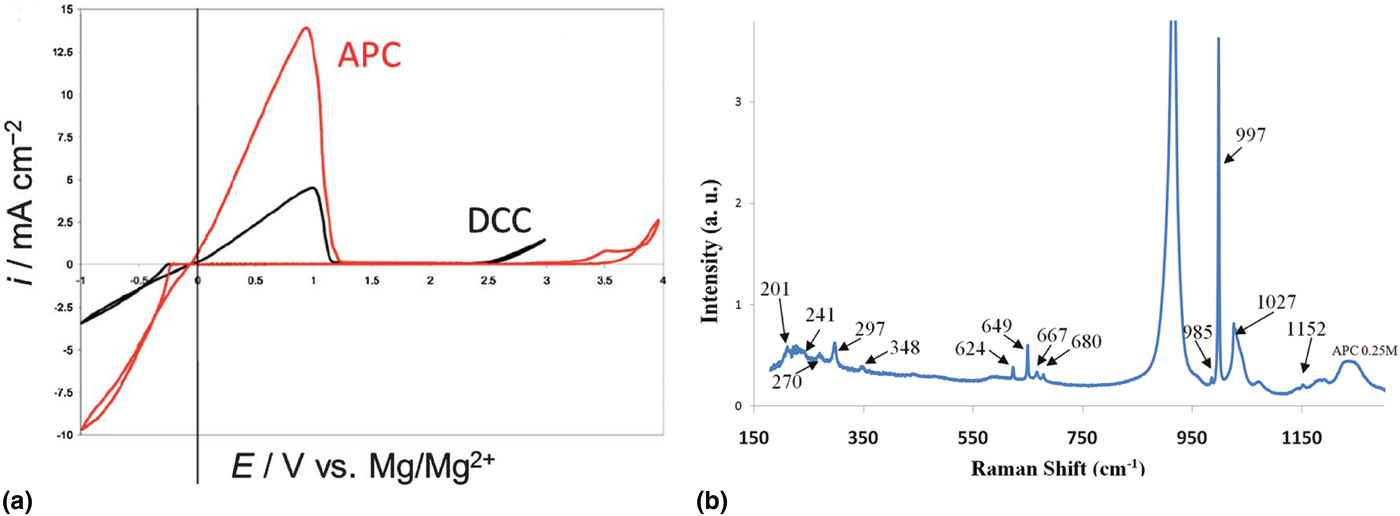
The common magnesium (Mg) analogues of Li ion conducting salts such as Mg(BF4)2, Mg(ClO4)2, etc. are not suitable for reversible stripping an plating of Mg ions in aprotic solvents because they either react with the anode or passivate the Mg.[ Reference Gregory, Hoffman and Winterton 5 , Reference Lu, Schechter, Moshkovich and Aurbach 21 ] Gregory et al. initially synthesized Mg electrolytes through the reaction of an organomagnesium with aluminum chloride (AlCl3) or trialkylborane (Lewis acid) in ethereal solvents.[ Reference Gregory, Hoffman and Winterton 5 ] Using the same synthetic concept, Aurbach et al. prepared the so-called DCC electrolytes through the reaction between Bu2Mg and EtAlCl2 in tetrahydrofuran (THF) and demonstrated the first prototype rechargeable Mg battery.[ Reference Aurbach, Cohen and Meshkovich 6 ] An optimized electrolyte APC was generated through reaction of PhMgCl and AlCl3, which exhibits an oxidative stability of 3.2 V versus Mg in cyclic voltammetric (CV) measurements [Fig. 1(a)], a conductivity of 5 mS/cm (30 °C) and a cycling efficiency of almost 100%.[ Reference Aurbach, Suresh, Levi, Mitelman, Mizrahi, Chusid and Brunelli 22 ] Spectroscopic analysis revealed that these solutions contain multiple species, including MgCl+, Mg2Cl3 + as electrochemical active species, Ph n AlCl4−n − (n = 1–3), MgCl2, Ph2Mg, and PhMgCl resulting from various transmetalations of the ligands and the Schlenk equilibrium [Fig. 1(b)].[ Reference Vestfried, Chusid, Goffer, Aped and Aurbach 23 , Reference Pour, Gofer, Major and Aurbach 24 ]
(a) Comparative cyclic voltammograms of APC and DCC electrolyte solutions on Pt electrodes. Reproduced with permission from Ref. Reference Aurbach, Suresh, Levi, Mitelman, Mizrahi, Chusid and Brunelli22. Copyright (2007) WILEY–VCH Verlag GmbH & Co. KGaA, Weinheim. (b) Raman spectrum of a 0.25 M APC solution. Reprinted with permission from Ref. Reference Pour, Gofer, Major and Aurbach24. Copyright (2011) American Chemical Society.

Other approaches have also been explored by replacing AlCl3 with other Lewis acids such as tri(3,5-dimethylphenyl)borane (Mes3B) and aluminum triphenoxide [Al(OPh)3] to react with PhMgCl.[ Reference Guo, Zhang, Yang, Wang, Li and Hirano 25 , Reference Nelson, Brody, Kampf and Bartlett 26 ]
Although these organomagnesium based electrolytes show good electrochemical performance, they are complex chemical mixtures of various species that coexist under dynamic equilibrium in the ethereal solvents. The presence of organomagnesium components (RMgX and MgR2), which are highly nucleophilic and extremely air and moisture sensitive, precludes them from being used for the electrophilic cathodes such as S and air. These limitations have motivated research on non-nucleophilic electrolytes, which are both electrochemically and chemically suited for the incorporation S or air as cathode for potential high-energy Mg batteries.
Non-nucleophilic magnesium electrolytes
Hauser base-based electrolytes
The reversible Mg deposition of the non-nucleophilic Hauser-base hexamethyldisilazide magnesium chloride (HMDSMgCl) was first reported by Liebenow et al.,[ Reference Liebenow, Yang and Lobitz 27 ] and the electrolyte showed superior electrochemical properties compared with those of Grignard reagent-based electrolytes. Later, Muldoon and co-workers applied the previously established strategy from Aurbach by adding AlCl3 to the solution of Liebenow's electrolyte HMDSMgCl and observed an increased current density for Mg plating/stripping. The electrolyte was purified by re-dissolving the recrystallized products in THF, achieving a voltage stability of 3.2 V. The compatibility of the system with a S cathode was verified.[ Reference Kim, Arthur, Allred, Zajicek, Newman, Rodnyansky, Oliver, Boggess and Muldoon 28 ] From a practical point of view, the Grignard reagent EtMgCl2, which is needed for the preparation of the precursor compound HMDSMgCl and the necessary purification step generate a great deal of synthetic expenses.
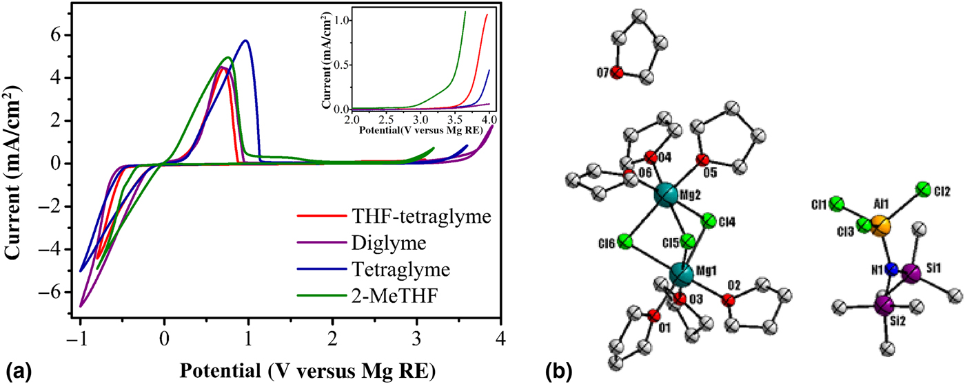
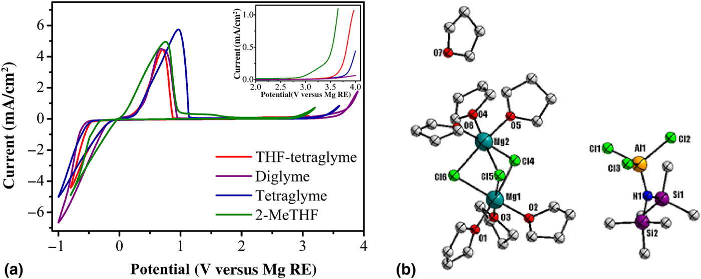
Zhao-Karger et al. established a convenient approach toward the non-nucleophilic electrolytes through a simple one-step reaction of magnesium-bis(hexamethyldisilazide) (HMDS)2Mg and AlCl3 at the ratio of 1 : 2 in ethereal solvents.[ Reference Zhao-Karger, Zhao, Fuhr and Fichtner 29 ] The in situ generated electrolytes in THF show an oxidative voltage of about 3.3 V, which is as good as the solution prepared by re-dissolving crystals. As this reaction can be conducted also in other solvents, higher stabilities are possible [Fig. 2(a)]. Quantitative crystals were isolated from the THF solution and the structure was confirmed by single-crystal x-ray diffraction as [Mg2(μ-Cl)3·6THF][HMDSAlCl3]·THF [Fig. 2(b)].
(a.) Cyclic voltammograms of the Mg deposition/dissolution of (HMDS)2Mg–2AlCl3 in different solvents on Pt electrode at a scan rate of 25 mV/s. (b) ORTEP plot (50% thermal probability ellipsoids) of [Mg2(μ-Cl)3·6THF][HMDSAlCl3]·THF. Hydrogen atoms are omitted for clarity. Reprinted from Ref. Reference Zhao-Karger, Zhao, Fuhr and Fichtner29 with permission from the Royal Society of Chemistry.
Nuclear-magnetic resonance spectroscopic (NMR) and mass spectrometric (MS) characterization confirm that the reaction (1), in which the Mg2Cl3 + cation is in the known equilibrium (2):
 $$\eqalign{& ({\rm HMDS})_{\rm 2}{\rm Mg + 2AlC}{\rm l}_{\rm 3} \to {\rm [M}{\rm g}_{\rm 2}{\rm C}{\rm l}_{\rm 3}{\rm ][HMDSAlC}{\rm l}_{\rm 3}{\rm ]} \cr & +{\rm HMDSAlC}{\rm l}_{\rm 2}} $$
 $${\rm M}{\rm g}_{\rm 2}{\rm C}{\rm l}_{\rm 3} ^{\hskip3pt\rm +} \leftrightarrow {\rm MgC}{\rm l}^{\rm +} + {\rm MgC}{\rm l}_{\rm 2}$$
This type of reactions has been used for the synthesis of organoaluminum compounds RAlCl2,[ Reference Seidel 30 ] in which one equivalent of organomagnesium R 2Mg reacts with two equivalents of AlCl3, followed by the addition of a non-polar solvent to shift the equilibrium (2) to the right direction, while the RAlCl3 − anion transfers one Cl− to MgCl+ ion forming the product RAlCl2:
 $$R_{\rm 2}{\rm Mg + 2AlC}{\rm l}_{\rm 3} \to {\rm [M}{\rm g}_{\rm 2}{\rm C}{\rm l}_{\rm 3}{\rm ][}R{\rm AlC}{\rm l}_{\rm 3}{\rm ] +} R{\rm AlC}{\rm l}_{\rm 2}$$
 $$R{\rm AlC}{\rm l}_{\rm 3} ^ {\hskip2pt -} {\rm + M}{\rm g}_{\rm 2}{\rm C}{\rm l}_{\rm 3} ^{\hskip3pt \rm +} \to {\rm MgC}{\rm l}_{\rm 2}{\rm +} R{\rm AlC}{\rm l}_{\rm 2} $$
These results indicate that the combination of (HMDS)2Mg with 2AlCl3, in accordance with the reaction stoichiometry, leads to exclusive HMDSAlCl3 − anions in the solution. This is the obvious reason for the superior electrochemical performance when compared with the electrolyte generated from HMDSMgCl–AlCl3 containing several anionic species in form HMDS n AlCl4−n − (n = 1–3).[ Reference Kim, Arthur, Allred, Zajicek, Newman, Rodnyansky, Oliver, Boggess and Muldoon 28 ] Owing to the favorable electrochemical and chemical properties and its simplicity in preparation, this type of electrolyte has been employed in different Mg battery systems with both intercalation and conversion cathodes, including Mo6S8,[ Reference Zhao-Karger, Zhao, Fuhr and Fichtner 29 ] vanadium oxychloride (VOCl),[ Reference Minella, Gao, Zhao-Karger, Mu, Diemant, Pfeifer, Chakravadhanula, Behm and Fichtner 31 ] S,[ Reference Zhao-Karger, Zhao, Wang, Diemant, Behm and Fichtner 32 – Reference Yu and Manthiram 35 ] Se,[ Reference Zhao-Karger, Lin, Bonatto Minella, Wang, Diemant, Behm and Fichtner 36 ] and iodine.[ Reference Tian, Gao, Li, Wang, Luo, Fan, Yang, Suo and Ma 37 ]
Fluorinated alkoxide-based electrolytes
Apart from amido groups, some research groups also explored the feasibility with alkoxide magnesium chlorides ROMgCl using the Lewis acid–base concept. Wang et al. employed the phenolate magnesium chlorides RPhOMgCl to react with AlCl3 in THF and demonstrated highly reversible Mg deposition/dissolution.[ Reference Wang, Guo, Yang, Nuli and Hirano 38 ] Bartlett and co-workers studied the substituent effects on the electrochemical behaviors of the RPhOMgCl-type electrolytes.[ Reference Nelson, Kampf and Bartlett 39 , Reference Crowe and Bartlett 40 ] When R is a strongly electron withdrawing group such as 4-CF3, the electrolyte exhibits an anodic stability of 2.9 V and ionic conductivity of 2.2 mS/cm. Reference Liebenow, Yang and Lobitz 27 Al NMR study revealed that several (RPhO) x AlCl4−x − (x = 1–4) species are present in the solution, similarly to the reactions of organomagnesium chlorides with AlCl3. The same group recently carried out the reaction of fluorinated alkoxy magnesium chlorides F ROMgCl with AlCl3 and investigated the electrolyte performance.[ Reference Crowe, Stringham and Bartlett 41 ] According to their comparison studies, a solution composed of 1.2 M [(CF3)2(CH3)]COMgCl and 0.20 M AlCl3 in THF exhibits an anodic stability of 3.2 V and an ionic conductivity of 3.5 mS/cm, which is in accordance with the trends of the calculated HOMO energies.
To circumvent the need of the Grignard reagent for the synthesis of ROMgCl, Arnold and co-workers combined magnesium dialkoxides Mg(OR)2 (R = alkyl, aryl) with AlCl3 to form Mg electrolyte.[ Reference Herb, Nist-Lund, Schwartz and Arnold 42 ] The solution obtained from the combination of fluorinated magnesium dialkoxide Mg(HFIP)2 (HFIP = 1,1,1,3,3,3-hexafluoro-2-propanol) and AlCl3 in 1,2-dimethoxyethane (DME) exhibits promising electrochemical properties such as anodic voltage >3 V on Pt electrode, nearly 100% coulombic efficiency for Mg cycling and a conductivity of 4.77 mS/cm (26.3 °C).[ Reference Herb, Nist-Lund and Arnold 43 ]
In comparison to the organomagnesium-based electrolytes, the combinations of less reactive reagents such as amides, alkoxides with AlCl3 improve the electrolytes with respect to chemical compatibility and safety features without sacrificing their electrolytic properties. The fluorinated alkoxide-based electrolytes should be chemically compatible with S. However, they have not been investigated for Mg–S batteries so far.
Magnesium chloride-based electrolytes
In recent years, Mg electrolytes based on inexpensive and practically convenient MgCl2 have been reported by several research groups. A short review about such electrolytes has been published in 2016.[ Reference He, Nielson, Luo and Liu 44 ] Herein we will briefly summarize the versatile utilities of MgCl2 in Mg electrolytes.
It is known in chemistry that MgCl2 can interestingly act both as Lewis acid and base depending on the reaction counterparts. The reaction of MgCl2 with a strong base results in a magnesiate anion with the formula R n MgCl3 −n − (n = 1–3) by accepting a ligand from the base counterpart.[ Reference Rappoport and Marek 45 ] With an acid, MgCl2 tends to form the binuclear cation Mg2Cl3 + by transferring one chlorine atom to its acid counterpart. The organoaluminum Lewis acid acts as a Cl acceptor and converts into a tetrakis-ligated aluminate by taking a chloride from MgCl2. This reaction has been often used to formulate new Mg electrolytes as shown in the following.
Combinations of magnesium chloride with aluminum-based Lewis acids
The first study on the MgCl2–AlCl3 electrolyte showed high overpotential and low efficiency for Mg cycling, and co-deposition of Al.[ Reference Viestfrid, Levi, Gofer and Aurbach 46 ] In 2014, Doe et al. resumed this combination and demonstrated that the DME solution of MgCl2–AlCl3, the so called “MACC” in a ratio of 3 : 2 offers an anodic stability of 3.1 V versus Mg, Coulombic efficiency of 99% and conductivity of 2 mS/cm (25 °C).[ Reference Doe, Han, Hwang, Gmitter, Shterenberg, Yoo, Pour and Aurbach 47 ] As a full inorganic electrolyte, the MACC electrolyte has drawn much attention in the community, and has been extensively studied in recent years.[ Reference Barile, Barile, Zavadil, Nuzzo and Gewirth 48 – Reference He, Luo and Liu 52 ] Recently, Li et al. synthesized the MACC electrolyte in binary solvents of THF and N-methyl-N-butyl-pyrrolidinium bis(trifluoromethanesulfonyl)imide. Single-crystal x-ray diffraction reveals the solid structure with the ion pair [Mg(THF)6]2+[AlCl4]−.[ Reference Li, Cheng, Wang, Qiu, Zheng, Lin, Nanda, Ma and Xu 53 ]
The oxidative stability of 2.5 V versus Mg on Pt electrode for this electrolyte is inferior to the reported MACC solution in a pure ethereal solvent and the ionic liquid possibly contributed to the high ionic conductivity of the electrolyte (8.5 mS/cm).[ Reference Li, Cheng, Wang, Qiu, Zheng, Lin, Nanda, Ma and Xu 53 ] More recently, Luo et al. reported the beneficial effects of post-treatment with Mg powder on the electrochemical performance of MgCl2/AlCl3 electrolytes in ethereal solvents.[ Reference Luo, He and Liu 54 ] It should be noted that it is known that AlCl4 − anion is capable of Al deposition and has been used as active anion for Al batteries.[ Reference Lin, Gong, Lu, Wu, Wang, Guan, Angell, Chen and Dai 55 ] The Al co-deposition has been found in the work on MACC as well.[ Reference Barile, Barile, Zavadil, Nuzzo and Gewirth 48 ]
Liu et al. and Zhao-Karger et al. simultaneously reported their studies on electrolytes based on MgCl2–Al Lewis acid combinations.[ Reference Liu, Shao, Li, Gu, Hu, Xu, Nie, Chen and Wang 56 , Reference Zhao-Karger, Mueller, Zhao, Fuhr, Jacob and Fichtner 57 ]
 $${\rm 2MgC}{\rm l}_{\rm 2} + R_n{\rm AlC}{\rm l}_{{\rm 3 -} n} \to {\rm M}{\rm g}_{\rm 2}{\rm C}{\rm l}_{\rm 3}^{\hskip3pt\rm +} + R_n{\rm AlC}{\rm l}_{{\rm 4 -} n}^{\hskip11pt\rm -} $$
Liu et al. reacted MgCl2 with a Lewis acid to yield the electrolyte.[ Reference Liu, Shao, Li, Gu, Hu, Xu, Nie, Chen and Wang 56 ] The Lewis acid–base pairs MgCl2–AlEtCl2 and MgCl2–AlPh3 in THF exhibited an voltage stability of 3.1 and 2.9 V on glassy carbon or Pt electrode, respectively. In addition, experiments on sulfur compatibility indicated that these electrolytes, except the one generated from MgCl2–AlPh3, were chemically unchanged when S powder was added.
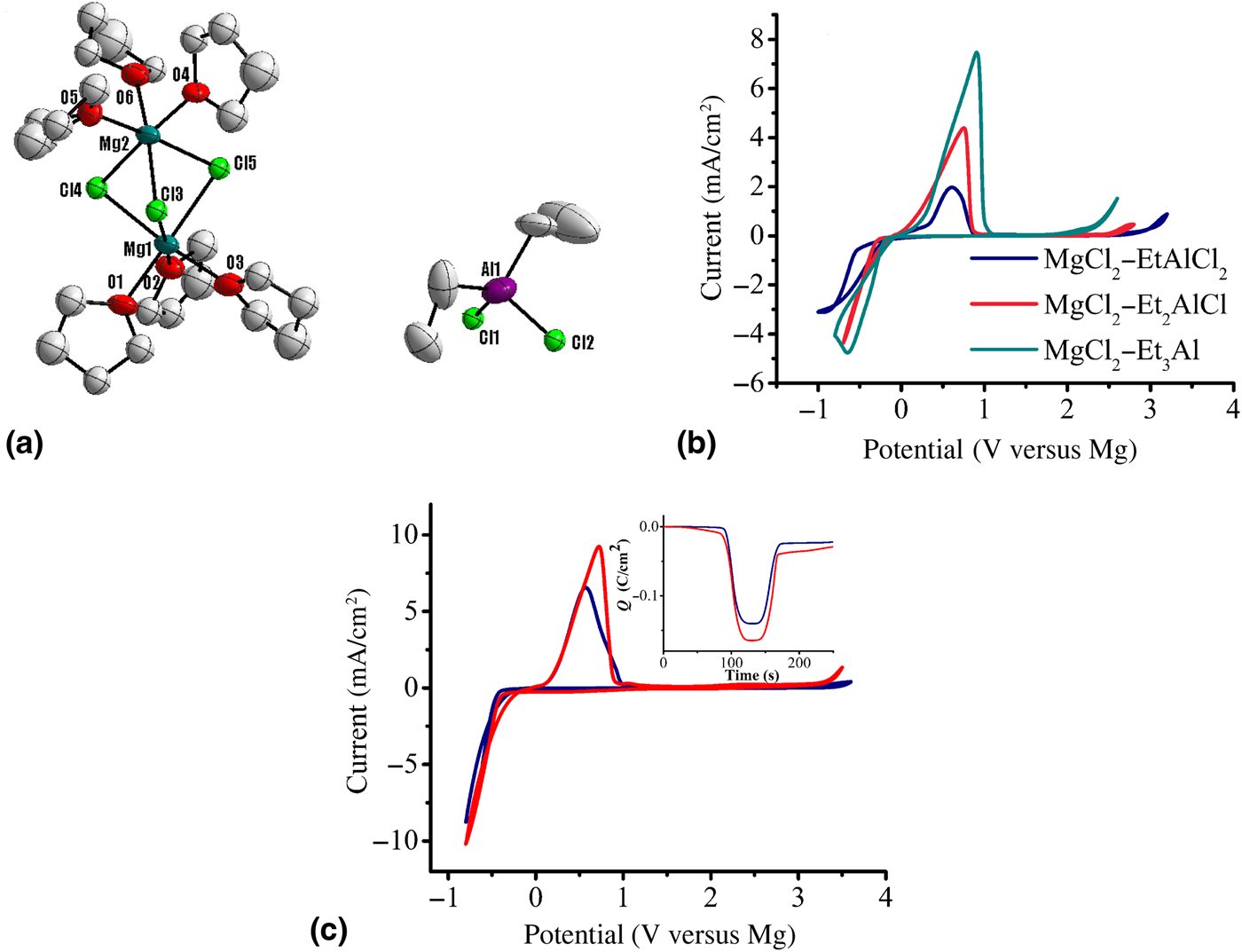
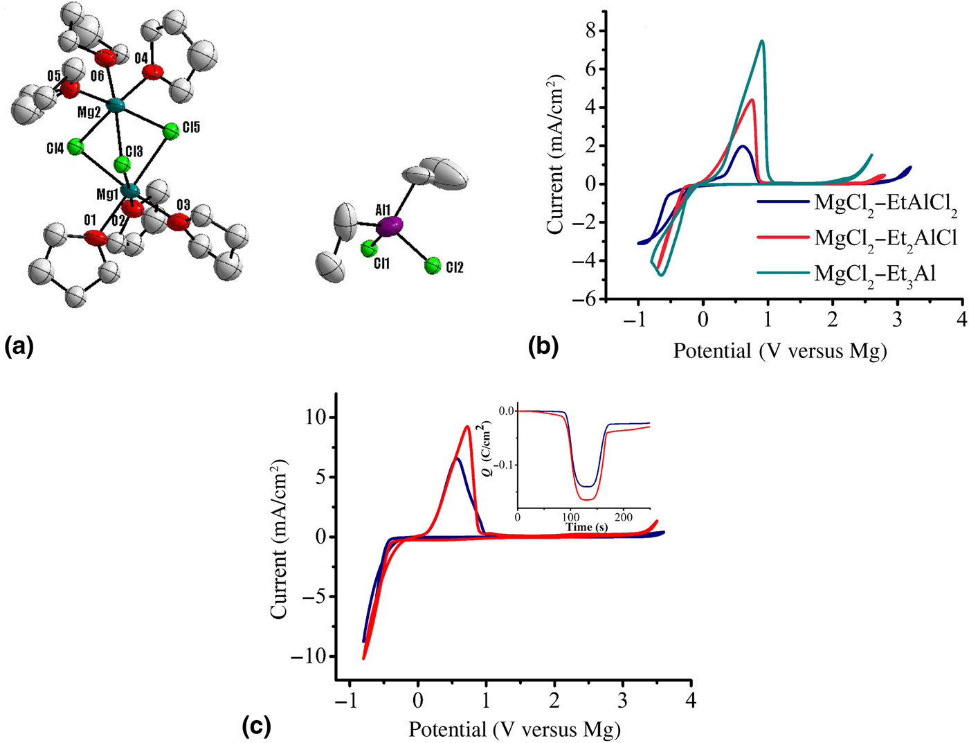
Zhao-Karger et al., with the intention to validate the transmetalation reaction (5), investigated the reactions of MgCl2 with Et n AlCl3 −n (n = 1–3) in ethereal solutions.[ Reference Zhao-Karger, Mueller, Zhao, Fuhr, Jacob and Fichtner 57 ] The crystal structure of the dimeric complex [Mg2(μ-Cl)3·6THF][Et2AlCl2] resulting from the mixture of MgCl2–Et2AlCl confirmed the supposed reaction (5) [Fig. 3(a)]. All the solutions are capable of reversible Mg deposition. Figure 3(b) illustrates representative cyclic voltammograms of the tetraglyme solutions, in which the electrolyte based on the combination of MgCl2 and EtAlCl2 exhibits the highest anodic stability up to 2.9 V. Zhao-Karger et al. additionally applied this straightforward synthesis to yield an air-stable phenolate electrolyte.[ Reference Zhao-Karger, Mueller, Zhao, Fuhr, Jacob and Fichtner 57 ] The 0.6 M diglyme solution resulting from reaction of MgCl2 and dichloroaluminum phenolate PhOAlCl2 demonstrates an anodic stability of 3.4 V [Fig. 3(c)], which is 0.7 V higher than that reported for a solution prepared by the reaction of PhOMgCl and AlCl3 in THF.[ Reference Wang, Guo, Yang, Nuli and Hirano 38 ]
(a) ORTEP plot (50% thermal probability ellipsoids) of [Mg2(μ-Cl)3·6THF][Et2AlCl2]. Hydrogen atoms are omitted for clarity. Cyclic voltammograms: (b) MgCl2–Et n AlCl3−n (n = 1–3) electrolytes; (c) MgCl2–PhOAlCl2 electrolytes under argon (blue) and after being stirred in dry air overnight (red); inset shows the charge balance of Mg deposition/dissolution, on Pt electrode at a scan rate of 25 mV/s. Reprinted from Ref. Reference Zhao-Karger, Mueller, Zhao, Fuhr, Jacob and Fichtner57 with permission from the Royal Society of Chemistry.
These results indicate that the reactions between MgCl2 and organoaluminum compounds can lead almost purely to the electrochemically active binuclear Mg complexes, more efficiently and convenient compared to the alternative approaches with organomagnesium and alkoxide magnesium chlorides. This reaction was also used to modify the bisamide based electrolyte.[ Reference Zhao-Karger, Zhao, Wang, Diemant, Behm and Fichtner 32 ] With addition of MgCl2, the initial byproduct (HMDS)AlCl2 in the Mg(HMDS)2–AlCl3 electrolyte is transformed to the active species [Mg2Cl3]+[HMDSAlCl3]−. Thus, the concentration of HMDS electrolyte can be increased to 1.8 M.
Miscellaneous combinations
Pellion technologies patented the preparation of non-aqueous electrolyte through the reaction of MgCl2 and magnesium bis(trifluoromethane sulfonyl)imide [Mg(TFSI)2] at varying molar ratios in ethereal solvents and ionic liquid N,N-propyl-methyl-pyrrolidinium-bis(trifuoromethylsulfonyl)imide. The electrolyte solution in DME exhibits an voltage stability of ~3.5 V on Pt and ionic conductivity >5 mS/cm (28 °C).[ Reference Robert, George, Robert and Jaehee 58 ] Aurbach and co-workers studied the role of the chloride anions for the enhancement of the reversible Mg deposition of Mg(TFSI)2.[ Reference Shterenberga, Salamaa, Yoob, Gofera, Parkc, Sunc and Aurbach 59 ] Recently, Sa et al. also reported the enhancement of the electrochemical activity of Mg(TFSI)2 in THF and diglyme through addition of MgCl2.[ Reference Sa, Pan, Saha-Shah, Hubaud, Vaughey, Baker, Liao and Burrell 60 ] Single-crystal x-ray diffraction unveils the solid structure with the ion pair [Mg2Cl3(THF)6]+[TFSI]−.
Liao et al. reported the reaction of Mg(HMDS)2 with MgCl2 in THF at 1 : 4 ratio, showing an anodic stability of 2.8 V and good reversibility.[ Reference Liao, Sa, Key, Burrell, Cheng, Curtiss, Vaughey, Woo and Hu 61 ] The same group also made an extended study on the reactions of MgCl2 with phenolate/alkoxide Mg chlorides.[ Reference Pan, Huang, He, Brombosz, Vaughey, Zhang, Burrell, Zhang and Liao 62 ] The electrolytes prepared by reacting (tBuO)MgCl–MgCl2 in THF exhibited anodic stability up to 3.3 V and close to 100% efficiency.
These results reflect the great diversity of the Mg coordination chemistry. In contrast to the well-known electrochemical activity of the Mg2Cl3 + cation, the mechanism of reversible Mg deposition from anionic Mg species is still unexplored. One of a drawback of this type of electrolytes is that the phenolate/alkoxide MgCl2 need to be synthesized from Grignard reagent EtMgCl in THF under stringent conditions.
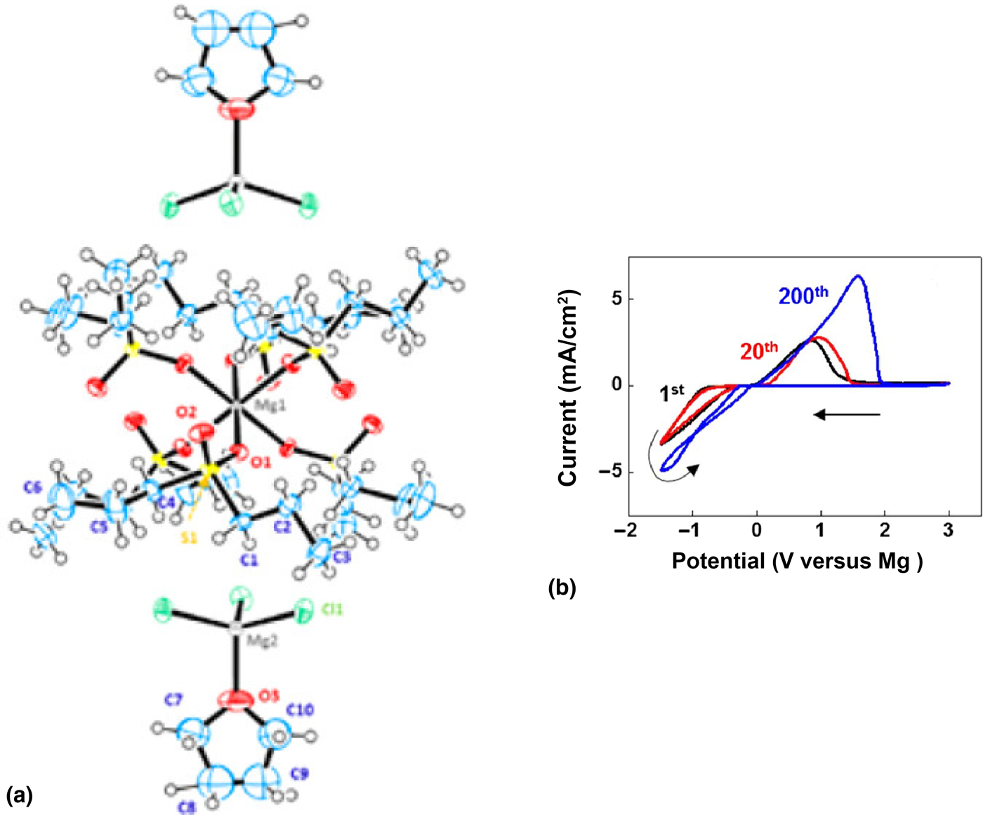
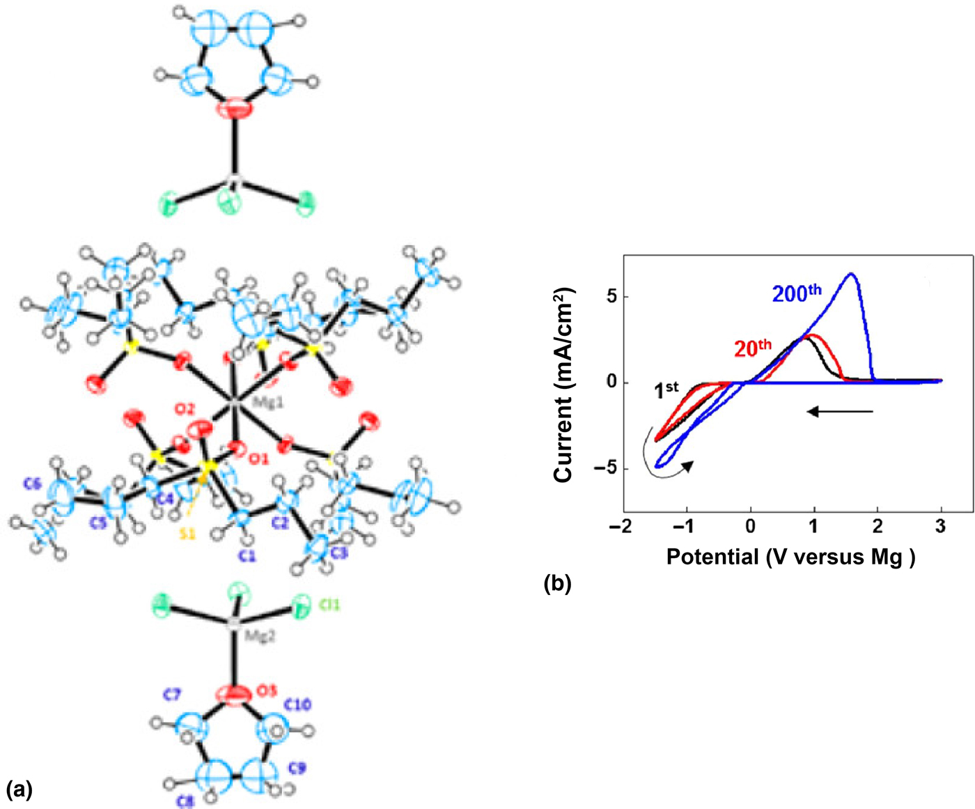
More recently, Lee and co-workers[ Reference Kang, Lim, Kim, Heo, Hwang, Jang, Yang, Hong and Lee 63 ] reported that: MgCl2 in a mixture of dipropyl sulfone (DPSO) and THF yields crystals with an interesting solid structure where [Mg(DPSO)6]2+ cation pairs two [MgCl3(THF)]− anions [Fig. 4(a)]. A DPSO/THF (1/1, v/v) solution with MgCl2 salt shows a high reversibility of Mg deposition/dissolution, exhibiting an oxidative stability of about 3.0 V [Fig. 4(b)]. An Mg cycling efficiency of >90% and an ionic conductivity of 1.1 mS/cm (30 °C) were measured.
(a) X-ray crystal structure of Mg salt in DPSO/THF (Mg, gray; Cl, green; O, red; S, yellow; C, blue). (b) The 1st, 20th, and 200th cyclic voltammograms in DPSO/THF, Mo as the working electrode at 25 °C and a scan rate of 20 mV/s. Reproduced with permission from Ref. Reference Kang, Lim, Kim, Heo, Hwang, Jang, Yang, Hong and Lee63. Copyright (2017) American Chemical Society.
Electrolytes from chloride-free magnesium salts
Although great progress has been achieved in developing Mg electrolytes, the above-mentioned electrolytes are generally generated through Lewis base–acid or transmetalation reactions yielding the binuclear [Mg2(μ-Cl)3(THF)6]+ cation and anions in equilibria, which have great influences on the properties of the electrolytes.[ Reference Pour, Gofer, Major and Aurbach 24 , Reference Zhao-Karger, Mueller, Zhao, Fuhr, Jacob and Fichtner 57 ] In addition, corrosion on metallic current collectors has been verified with such chloride ion containing electrolytes.[ Reference Yagi, Tanaka, Ichikawa, Ichitsubo and Matsubara 64 , Reference Wall, Zhao-Karger and Fichtner 65 ] It has therefore been one of the goals to develop highly ion conductive Mg salts, which have favorable electrolytic characteristics, are chemically compatible with the electrode materials and non-corrosive against battery parts. In addition, they should be non-toxic, stable at ambient conditions, and be economically prepared from low-cost starting materials.
Mohtadi et al. reported the capability of reversible Mg deposition of magnesium borohydride [Mg(BH4)2] in glymes.[ Reference Mohtadi, Matsui, Arthur and Hwang 66 ] Kar et al. showed both experimentally and theoretically the reversible Mg redox behavior of Mg(BH4)2 in alkoxy-ammonium-based ionic liquids.[ Reference Kar, Ma, Azofra, Chen, Forsyth and MacFarlane 67 ] Watkins et al. have recently designed ionic liquids with a polyether chain attached to an organic pyrolidinium cation to chelate the Mg ion.[ Reference Watkins, Kumar and Buttry 68 ] Mg(BH4)2 dissolved in this ionic liquid showed superior coulombic efficiency and higher current density compared with the THF solutions. However, the low anodic stability (1.7 V versus Mg) makes Mg(BH4)2 unsuitable for practical Mg batteries.
Expanding on the early work on Mg(BBu4)2 of Gregory et al.,[ Reference Gregory, Hoffman and Winterton 5 ] Muldoon et al. synthesized several magnesium organoborates such as Mg(BPh4)2 and Mg(BArF)2, BArF = tetrakis[3,5-bis(trifluoromethyl)phenyl] borate.[ Reference Muldoon, Bucur, Oliver, Zajicek, Allred and Boggess 69 ] However, the solutions of such complexes either have low-voltage stability or are incapable of Mg deposition.
Ha et al. demonstrated the reversible Mg deposition of commercially available salt Mg(TFSI)2 when dissolved in glyme.[ Reference Ha, Lee, Woo, Koo, Kim, Cho, Lee and Choi 70 ] However, this electrolyte shows a high overpotential (about 2 V) and a low cycling efficiency. Recently, Ma et al. reported the enhancement of electrochemical properties of Mg(TFSI)2 tetraglyme solution by adding some quantities of Mg(BH4)2 to scavenge water and suggested that removal of water from the electrolytes is vital to achieve reversible Mg cycling.[ Reference Ma, Kar, Xiao, Forsyth and MacFarlane 71 ] The overpotential between Mg reduction and oxidation was reduced to 0.35 V with this approach, but the high oxidative stability of Mg(TFSI)2 was also sacrificed due to the presence of Mg(BH4)2.
In another attempt, the TOYOTA group tried to take advantage from the well-known stability of boron cages (closo-boranes) and Tutusaus et al. reported magnesium monocarborane (MMC) Mg(CB11H12)2 in glyme, which exhibits favorable electrolytic properties with high anodic stability of 3.8 V and high Mg cycling efficiency.[ Reference Tutusaus, Mohtadi, Arthur, Mizuno, Nelson and Sevryugina 72 ] Recently, they also studied the interfacial phenomena between Mg metal and the selected electrolytes including MMC an Mg(TFSI)2 solutions.[ Reference Tutusaus, Mohtadi, Singh, Arthur and Mizuno 73 ] McArthur et al. synthesized the same compound with an alternative method.[ Reference McArthur, Geng, Guo and Lavallo 74 ] The same group also prepared Mg salt with smaller 10-vertex closo-carborane anions.[ Reference McArthur, Jay, Geng, Guo and Lavallo 75 ] The tetraglyme solution of such salt enables the Mg electrolyte with an oxidative stability >3.5 V. However, the nontrivial multistep synthesis of the starting materials and the associated high costs are the major drawbacks of such compounds from an application point of view.
Magnesium hexafluorophosphate Mg(PF6)2 was investigated when dissolved in THF/CH3CN (acetonitrile).[ Reference Keyzer, Glass, Liu, Bayley, Dutton, Grey and Wright 76 ] However, the CV data indicate that the electrolytes have a low efficiency for Mg plating/stripping. Magnesocene has also been proven to be capable of Mg plating/striping, but the extremely low conductivity and low-voltage stability hinders a practical application.[ Reference Schwarz, Pejic, Fischer, Marinaro, Jörissen and Wachtler 77 ]
Recently, Arnold and co-workers reported that magnesium hexafluoroisopropylaluminate Mg[Al(hfip)4]2 in ethereal solvents can reversibly deposit Mg with high oxidative stabilities (>3.5 V versus Mg/Mg2+) and conductivities (>6 mS/cm).[ Reference Herb, Nist-Lund and Arnold 78 ] This conductive salt solution was synthesized via a three-step reaction. Firstly, both educts of magnesium fluoroalkoxide Mg(hfip)2 and aluminumfluoroalkoxide Al(hfip)3 need to be synthesized, followed by mixing them in DME.
In 2017, Zhang et al. reported the Mg electrolytes containing boron-centered anions (BCM).[ Reference Zhang, Cui, Qiao, Guan, Xu, Wang, Hu, Du and Li 79 ] The authors initially carried out the reaction of MgF2 with tris(2H-hexafluoroisopropyl) borate B[OCH(CF3)2]3 (THFPB) and characterized the reaction as:
 $$\eqalign{& {\rm Mg}{\rm F}_{\rm 2}+ n{\rm DME} +{\rm 2B}[{\rm OCH}({\rm C}{\rm F}_{\rm 3})_{\rm 2}]_{\rm 3} \cr & \to {\rm [Mg}\left( {{\rm DME}} \right)_n{\rm ]}^{{\rm 2 +}} +{\rm [FB}[{\rm OCH}({\rm C}{\rm F}_{\rm 3})_{\rm 2}]_{\rm 3}{\rm ]}^{\rm -}} $$
The electrolytic properties of the reaction mixture using only 0.05 M MgF2 as Mg source were examined by CV measurements, showing reversible Mg deposition, but with large overpotential and low coulombic efficiency. Surprisingly, a new anion species tetra(hexafluoroisopropyl)borate anion (denoted as [TrHB]−) was detected in the initial solution after some CV cycles, implying an unanticipated side reaction during Mg cycling. In fact, THFPB was mixed with MgF2 in a molar ratio of 10 : 1, which is in excess of five times the supposed reaction stoichiometry of 2 : 1. Therefore, the BCM electrolytes prepared in this study contain the chemically reactive component, which are indeed incompatible with Mg anode.
As bulky and weakly coordinating anion (WCA) can be excellent candidates for the formulation of electrolyte salts in LIBs,[ Reference Krossing and Raabe 80 ] Zhao-Karger et al. considered to synthesize Mg salts containing fluorinated alkoxyborate and alkoxyaluminate anions used for electrolytes.[ Reference Zhao-Karger, Bardaji, Fuhr and Fichtner 81 ] This class of compounds has the formula of Mg[Z(OR F)4]2, Z = Al, B; R F = fluorinated alkyl group. In general, one can expect that weaker cation–anion interactions result in higher ionic conductivities. In this study, very robust and versatile routes were presented for synthesis of Mg alkoxyborates and Mg alkoxyaluminates in pure solid form, which can then be conveniently dissolved in various solvents and additionally mixed with additives to meet electrolyte and battery requirements.
The fluorinated Mg alkoxyborates can be synthesized by a one-pot reaction of Mg(BH4)2 with a fluorinated alcohol or an exchange reaction between a sodium alkoxyborate and magnesium halide in an ethereal solvent as expressed in the general Eqs. (7) and (8), respectively.
 $${\rm Mg}({\rm B}{\rm H}_{\rm 4})_{\rm 2}+ {\rm 8}{\rm R}^{\rm F}{\rm - OH} \to {\rm Mg[B}({\rm O}{\rm R}^{\rm F})_{\rm 4}{\rm ]}_{\rm 2} +{\rm 4}{\rm H}_{\rm 2} \uparrow $$
 $${\rm 2Na[B}({\rm hfip})_{\rm 4}{\rm ] }+{\rm MgB}{\rm r}_{\rm 2} \to {\rm Mg}[{\rm B}({\rm hfip})_{\rm 4}]_{\rm 2}+{\rm 2NaBr} \downarrow $$
The fluorinated alkoxyaluminate-based Mg salts can also be prepared through a metathesis reaction between Na[Al(hfip)4] and magnesium bromide (MgBr2) as Eq. (9)
 $${\rm 2Na}[{\rm Al}({\rm hfip})_{\rm 4}]+ {\rm MgB}{\rm r}_{\rm 2} \to {\rm Mg}[{\rm Al}({\rm hfip})_{\rm 4}]_{\rm 2} + {\rm 2NaBr} \downarrow $$
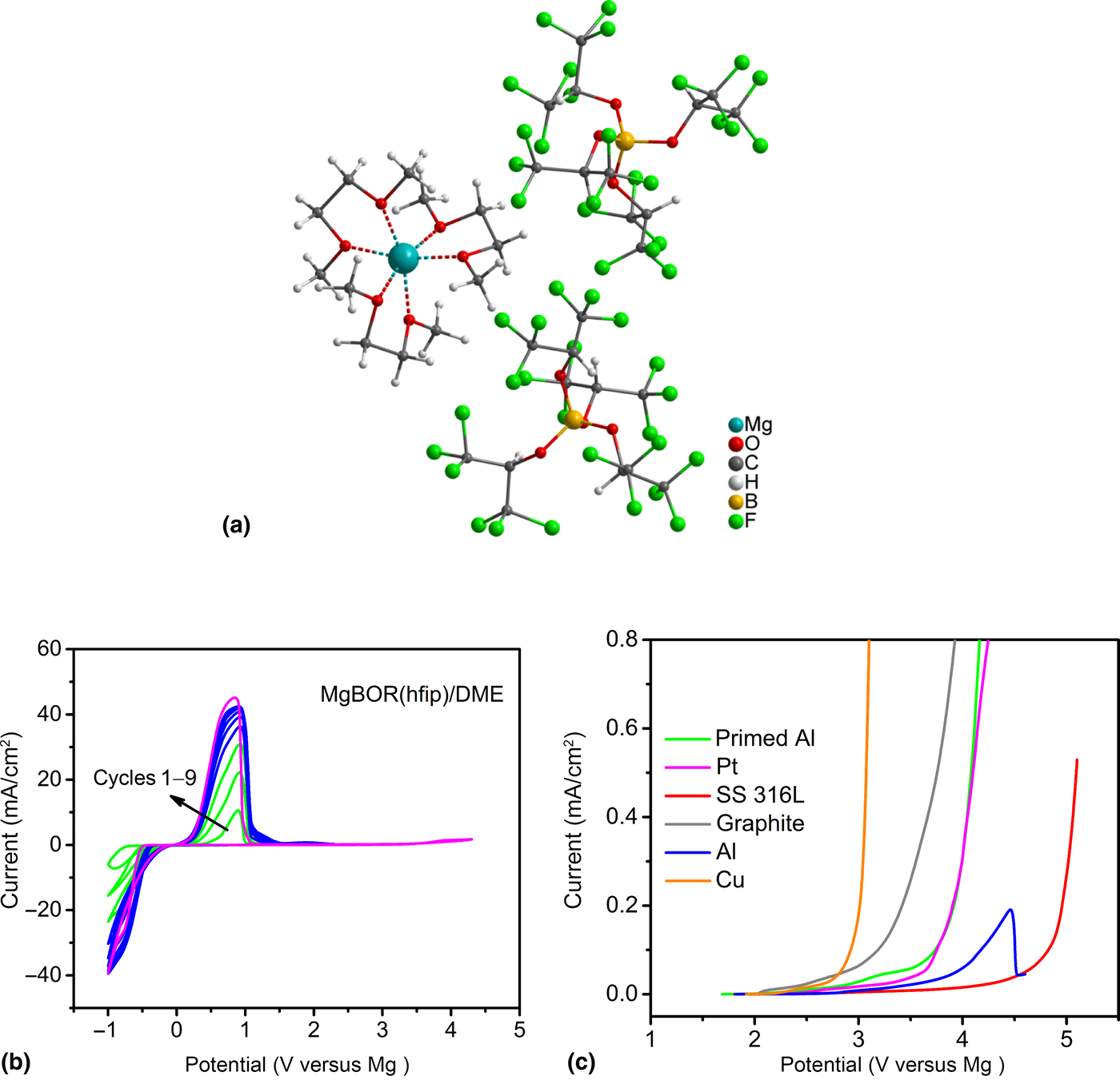
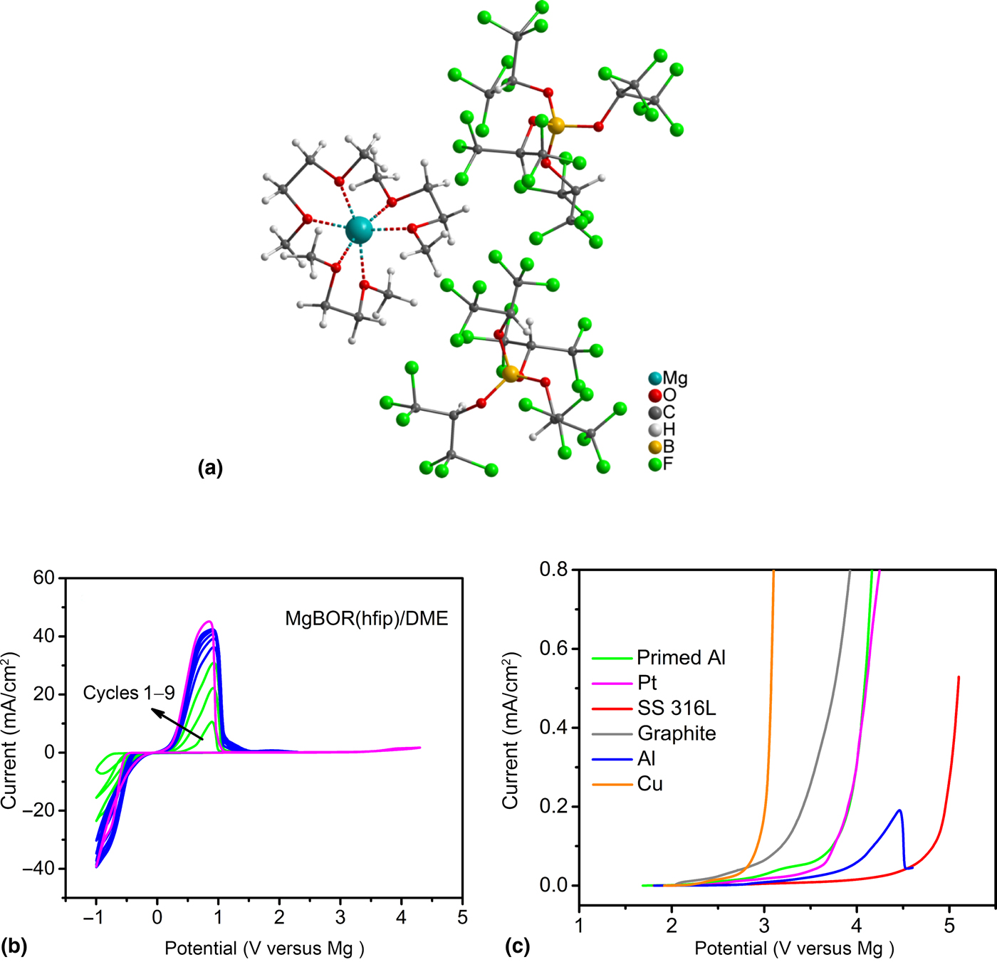
Magnesium tetrakis(hexafluoroisopropyloxy) borate (Mg[B(hfip)4]2) can be straightforwardly synthesized by the dehydrogenation reaction of Mg(BH4)2 with hexafluoro-2-propanol (hfip) in DME. The solid structure was determined by x-ray crystallography as Mg[B(hfip)4]2·3DME [Fig. 5(a)]. It consists of typical ionic pairs, in which the Mg2+ ion is coordinated by three DME molecules with a slightly distorted octahedral geometry. In the counter anion B(hfip)4 −, the boron (B) atom is bonded with four hexafluoroisopropyloxy groups with a tetrahedral geometry.
(a) Ball-and-stick representation of the Mg[B(hfip)4]2·3DME crystal. Electrochemical properties of Mg[B(hfip)4]2 in DME. (b) Cyclic voltammograms on Pt electrode at a scan rate of 25 mV/s. (c) Linear sweep voltammograms on various electrodes at a scan rate of 5 mV/s. Reprinted from Ref. Reference Zhao-Karger, Bardaji, Fuhr and Fichtner81 with permission from the Royal Society of Chemistry.
The thermal stability of Mg[B(hfip)4]2·3DME was examined to be stable up to 150 °C, where DME starts to release from the complex. Moreover, it has been proofed that Mg[B(hfip)4]2·3DME is fairly stable with addition of water and in ambient air, which is in sharp contrast to the homologous anion Al(hfip)4 − based salts being highly water sensitive.
Owing to the high electronegativity of fluorine atom, the fluorinated Mg alkoxyborates have good solubility in aprotic solvents, which make them suited for use in electrolytes. The 0.6 M DME solution of Mg[B(hfip)4]2 exhibited reversible Mg plating/stripping and a very high anodic stability [4.3 V on stainless steel (SS) electrode] [Figs. 5(b) and 5(c)]. A high ionic conductivity (6.8 mS/cm, at 25 °C) and coulombic efficiency (>99%) have also been detected.
Magnesium–sulfur batteries
Intercalation cathode materials have drawn a great deal of attention to be used for Mg batteries due to their potentially promising electrochemical characteristics that can result in high discharge voltage, high-energy density, and cycling stability. However, the strong electrostatic forces between the doubly charged Mg2+ ions and surrounding anions in crystal matrix makes the Mg2+ insertion reaction kinetics intrinsically slow. The electrochemical performance, e.g., cycling ability, cell voltage, and achievable capacity of the common intercalation compounds in Mg batteries falls far behind from that of in Li-ion batteries.[ Reference Canepa, Sai Gautam, Hannah, Malik, Liu, Gallagher, Persson and Ceder 15 ] So far, Mo6S8 is still the most successful cathode enabling effectively reversible Mg2+ ion insertion/extraction owing to its unique crystallographic structure.[ Reference Aurbach, Cohen and Meshkovich 6 ] However, the high molecular weight and the relatively low discharge voltage (<1.5 V versus Mg/Mg2+) leads to the low gravimetric energy density of the Mg cell. An alternative way to improve the energy density of an Mg battery is to utilize a conversion cathode with high capacity. The conversion of S to sulfide in the Mg–S cell may circumvent the sluggish Mg2+ insertion kinetic in intercalation cathodes.
As already mentioned, Mg–S battery possesses higher energy density compared to the Li–S system when graphite anode is used for the safety reasons caused by Li metal anode. With Mg metal as a safe anode, the Mg–S full cell could reach a theoretical-specific energy of 1722 Wh/kg and 3200 Wh/L, respectively, which are much higher than those of a Li2S/graphite cell (908 Wh/kg, 1100 Wh/L). In addition, the low cost of both Mg and S can make the Mg–S battery an attractive candidate for future battery generations. In the following, we summarize and discuss the recent progress on Mg–S batteries with different electrolytes.
Hexamethyldisilazide electrolytes
Muldoon et al. presented their non-nucleophilic HMDSMgCl–AlCl3 electrolyte in THF solution and the proof-of-concept of a Mg–S battery.[ Reference Kim, Arthur, Allred, Zajicek, Newman, Rodnyansky, Oliver, Boggess and Muldoon 28 ] In this study, the cell exhibited a low open-circuit voltage (OCV) of about 0.5 V and discharge voltage of 0.89 V (Fig. 6), which is only half of the theoretical cell voltage of 1.77 V. The initial discharge capacity reached 1200 mAh/g and the capacity declined to 394 mAh/g in the second cycle. The cell could be cycled for a few cycles with severe overcharging feature, which was attributed to the well-known polysulfide shuttle mechanism.
Discharge/charge behavior of the Mg–S cell in HMDSMgCl–AlCl3 electrolytes in THF. Reprinted with permission from Ref. Reference Kim, Arthur, Allred, Zajicek, Newman, Rodnyansky, Oliver, Boggess and Muldoon28. Copyright (2011) Nature Publishing Group.

Moreover, the HMDSMgCl–AlCl3 system restricts the opportunities to tune the physiochemical properties of the electrolyte by variation of the solvent because the crystalline product can be obtained in THF only.[ Reference Kim, Arthur, Allred, Zajicek, Newman, Rodnyansky, Oliver, Boggess and Muldoon 28 ] However, THF is not a proper solvent for electrolyte because of its low boiling point of 68 °C and high flammability.
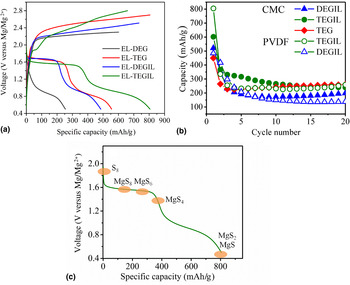
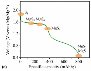
With the more convenient approach using (HMDS)2Mg and AlCl3,[ Reference Zhao-Karger, Zhao, Fuhr and Fichtner 29 ] it was demonstrated that the Mg–S batteries with the bisamide-based electrolytes in glymes or binary glyme and ionic liquid considerably outperform those with previous electrolytes solution in THF.[ Reference Zhao-Karger, Zhao, Wang, Diemant, Behm and Fichtner 32 ] As shown in Fig. 7(a), the OCVs in the cells were about 2 V. The cell using the electrolyte in diglyme (DEG) exhibited a sloping voltage profile with an initial discharge capacity of 250 mAh/g. However, with additional N-methyl-N-butyl-piperidinium bis(trifluoro methanesulfonyl)imide (IL) in the electrolyte, the cell containing DEGIL showed two discharge plateaus, in which flat discharge voltage plateau at 1.65 V is close to the theoretical emf value of 1.77 V. Both cells containing the electrolyte solution in tetraglyme (TEG) and in mixtures of tetraglyme and ionic liquid (TEGIL) resembled a voltage profile similar to that of DEGIL but delivering higher capacity of 550 and 800 mAh/g, respectively. The cells comprised of S cathode with PVDF or CMC as binder and the electrolyte TEGIL remained a reversible capacity of about 260 mAh/g after more than 20 cycles [Fig. 7(b)]. Based on ex situ studies by means of UV–vis and XPS, a reaction mechanism was proposed for the Mg–S cell.[ Reference Zhao-Karger, Zhao, Wang, Diemant, Behm and Fichtner 32 ] As shown in Fig. 7(c), S reduction reaction takes place in two steps: a fast solid–liquid two phase reduction forming high-order polysulfide (MgS8, MgS6, MgS4), followed by a slow liquid–solid reduction forming insoluble MgS2 and MgS. A fraction of the low-order Mg-PS produced during the first discharge is obviously not electrochemically active in the subsequent recharge any more, possibly due to high kinetic barriers originating from its insulating nature and insolubility.
Results with (HMDS)2Mg + AlCl3 electrolyte: (a) Initial discharge–charge curves of sulfur cathodes with PVDF binder. (b) Cycling performance of sulfur cathode in the electrolyte in diglyme/IL (blue), in tetraglyme/IL (green), in tetraglyme (red). (c) The proposed discharge mechanism of Mg–S cell. Reprinted with permission from Ref. Reference Zhao-Karger, Zhao, Wang, Diemant, Behm and Fichtner32. Copyright (2015) WILEY–VCH Verlag GmbH & Co. KGaA, Weinheim.

The study demonstrated the reversible cycling of Mg–S batteries at discharge voltage close to the theoretical voltage. However, it also indicated that the Mg–S system encounters critical problems such as the large overpotential during charge, polysulfide dissolution leading to loss of S in the cathode, capacity fading, and poor coulombic efficiency.
In a new attempt, Gao et al. introduced lithium bis(trifluoromethanesulfonyl)imide (LiTFSI) in the above-mentioned Mg bisamide-based electrolyte to enhance the reversibility of the Mg–S cell.[ Reference Gao, Noked, Pearse, Gillette, Fan, Zhu, Luo, Suo and Schroeder 33 ] The authors assumed that Li+ either undergoes an ion exchange reaction with MgS and MgS2, transforming them to rechargeable Li2S and Li2S2, or reacts with MgS and MgS2 to form the long-chain polysulfide MgLi-PS, thereby decreasing the kinetic barrier for re-oxidation of MgS and MgS2 (Fig. 8).
The proposed discharge mechanism of Mg/S Battery with LiTFSI Additive. Reprinted with permission from Ref. Reference Gao, Noked, Pearse, Gillette, Fan, Zhu, Luo, Suo and Schroeder33. Copyright (2015) American Chemical Society.

The cell demonstrated a capacity of 1000 mAh/g with two discharge plateaus at 1.75 and 1.0 V and stable capacity after 30 cycles. Considering the fact that electrolyte used in this work contains 1 M LiTFSI and 0.1 M Mg salt, this cell configuration can be also regarded as a dual ion battery.
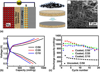
In order to transfer successful concepts in the development of Li–S batteries, a sulfur nanocomposite was fabricated as cathode material by dispersing S on the highly functionalized rGO (reduced graphene oxide) and improved cycling stability and rate capability of the Mg–S batteries.[ Reference Vinayan, Zhao-Karger, Diemant, Chakravadhanula, Schwarzburger, Cambaz, Behm, Kübel and Fichtner 34 ] Yu and Manthiram recently demonstrated an advanced cell design with a cathode comprising activated carbon nanofibers (CNFs) filled with sulfur powder and a CNF-coated separator.[ Reference Yu and Manthiram 35 ] The thin layer of CNF on the separator serves as both a polysulfide captor and a current collector.as shown in Fig. 9(a). In this study, the Mg–S cells with the bisamide-based HMDS-electrolyte delivered a remarkable discharge capacity of ~1200 mAh/g at the first discharge and last for 20 cycles without suffering a fast capacity decline after the first cycle [Figs. 9(b) and 9(c)].
(a) Schematic representation of a Mg–S cell with activated-CNF-coated separator(left), preparation of the CNF-coated separator (middle), scanning electron microscopy image of the CNF(right). (b) Discharge/charge profiles of the Mg–S cells at various C-rates. (c) Discharge capacities. Reprinted with permission from Ref. Reference Yu and Manthiram35. Copyright (2016) American Chemical Society.

The bisamide electrolytes have also been employed for Mg batteries with Se and selenium–sulfur (SeS2) cathode, respectively.[ Reference Zhao-Karger, Lin, Bonatto Minella, Wang, Diemant, Behm and Fichtner 36 ] The Se cathode delivered a reversible capacity of 480 mAh/cm3 for 50 cycles at a current rate of 2 C. The improved battery performance with a SeS2 cathode could give a perspective of new sulfur based cathode materials combining the merits of both Se and S.
MACC electrolytes
MACC electrolyte is based on the reaction of MgCl2 with two equivalents AlCl3 in binary solvent of THF and an ionic liquid. It is fully inorganic, it was supposed to be chemically compatible with S and has recently been tested for Mg–S batteries.[ Reference Li, Cheng, Wang, Qiu, Zheng, Lin, Nanda, Ma and Xu 53 ] With the nitrogen-doped graphene–sulfur (NG–S) cathode, the cell was cycled 20 times. However, the cells suffered from rapid capacity decline from 700 to 130 mAh/g in the first cycles, a low discharge potential (<1 V) and large overpotential (>1.5 V).
Conductive salt-based electrolytes
Recent progress on new chloride-free electrolytes mitigates corrosion of cell components and has inspired researchers to develop better Mg–S batteries. However, the Cl-free metal borohydrides MBH4 (M = Li, Na) can react with S forming sulfurated borohydrides, under evolution of hydrogen gas[ Reference Lalancette, Freche, Brindle and Laliberte 82 ] making Mg(BH4)2 chemically incompatible with sulfur. The more inert and more stable carborane-based electrolytes from the same group are supposed to be non-nucleophilic, but have not been employed for Mg–S cells so far.
Ha et al. have evaluated the battery performance of Mg–S cells using Mg(TFSI)2 in glyme as electrolyte.[ Reference Ha, Lee, Woo, Koo, Kim, Cho, Lee and Choi 70 ] The Mg/CMK3-S cell exhibited a very low-discharge plateau of 0.2 V with a capacity of 500 mAh/g in the first discharge and the cell could be cycled only for several cycles. Itaoka et al. prepared sulfur composites with S and bis(alkenyl) compound with a crown or linear ether unit.[ Reference Itaoka, Kim, Yamabuki, Yoshimoto and Tsutsumi 83 ] With the electrolyte solution of Mg(TFSI)2 in THF or CH3CN, the cell delivered the first discharge capacity of ~600 mAh/g, but rapid capacity drop appeared in the second cycle. Additionally, a very low-discharge voltage (<1 V) and a large voltage hysteresis (>1.5 V) were observed. These results indicate that Mg(TFSI)2 electrolytes are probably not suitable for the Mg–S cell.
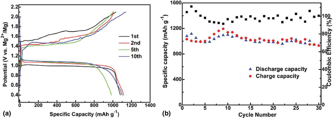
Recently, Zhang et al. prepared the so-called boron-centered anion-based magnesium (BCM) electrolyte and examined its utility for Mg–Se and Mg–S batteries.[ Reference Zhang, Cui, Qiao, Guan, Xu, Wang, Hu, Du and Li 79 ] A first discharge capacity of 1081 mAh/g was measured for the S cathode using the electrolyte with a surprisingly low Mg concentration of 0.05 M. A relatively flat discharge voltage plateau at about 1.1 V was reported. [Fig. 10(a)]. Interestingly, the overcharging behavior is much less significant compared with the previous reports and an overpotential during charge and discharge was <0.4 V. The Mg–S cells were cycled for 30 times with capacity retention >86% [Fig. 10(b)]. Se/C cathode reached a maximum specific capacity of 615 mAh/g in the 7th cycle and had capacity retention of 75% after 100 cycles.
The electrochemical performance of S/C cathodes: (a) Discharge/charge profiles, (b) Cycling behavior. Reprinted with permission from Ref. Reference Zhang, Cui, Qiao, Guan, Xu, Wang, Hu, Du and Li79. Copyright 2017 WILEY–VCH Verlag GmbH & Co. KGaA, Weinheim.

In the study, the authors revealed that the chemical composition of electrolyte from the initial reaction mixture changed during the CV cycling, namely one of the component reacted with Mg anode, forming a new electrochemical active anion.[ Reference Zhang, Cui, Qiao, Guan, Xu, Wang, Hu, Du and Li 79 ] This reaction can contribute to the discharge current in the cells and contribute to the measured capacities, which can be the reason for the capacity increase in the initial cycles of both systems.
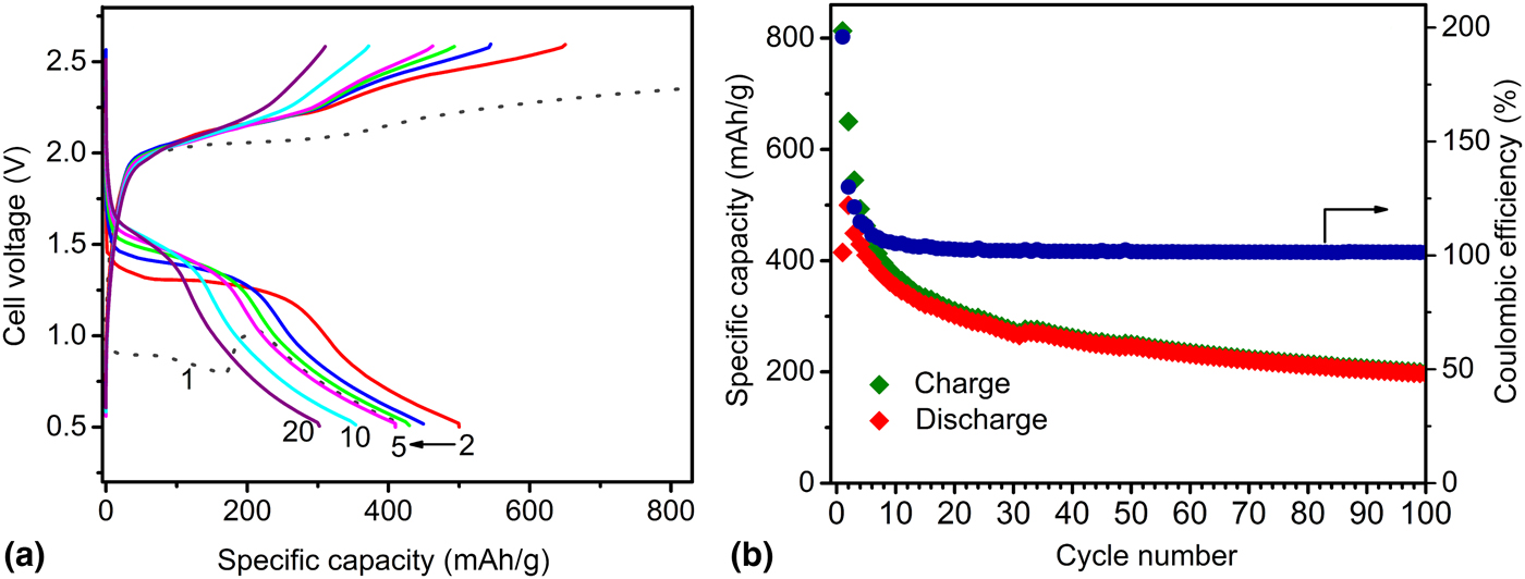
A recent study investigated the compatibility and electrochemical performance of new Mg[B(hfip)4]2 electrolytes in Mg–S cells.[ Reference Zhao-Karger, Bardaji, Fuhr and Fichtner 81 ] The sulfur cathode S/CMK-3 was prepared as previously described.[ Reference Zhao-Karger, Zhao, Wang, Diemant, Behm and Fichtner 32 ] The Mg–S cells were tested with the solution of Mg[B(hfip)4]2 in glymes. Figure 11(a) illustrates the discharge/charge curves for the extensive cycle at a current rate of 0.1 C (167 mA/cm2). The discharge voltage remained at about 1.5 V after the first cycles. A discharge capacity of ~200 mAh/g was retained after over 100 cycles [Fig. 11(b)]. The data indicate that the overcharging behavior is a serious issue, which needs to be resolved before the Mg–S battery can be regarded as a viable system.
Battery performance of the Mg–S cell using Mg[B(hfip)4]2 in diglyme/tetraglyme as electrolytes: (a) Discharge/charge profiles, (b) Cycling behavior. Reproduced from Ref. Reference Zhao-Karger, Bardaji, Fuhr and Fichtner81 with permission from the Royal Society of Chemistry.

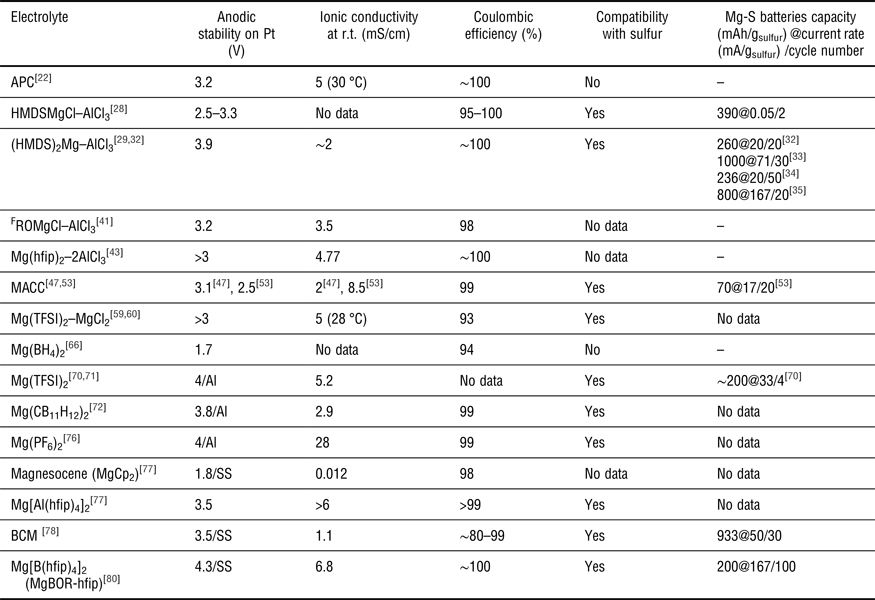
The properties of some electrolytes and their applications to Mg–S batteries are summarized in Table 1.
A comparison of some electrolytes and their utilities in Mg–S batteries.

Summary and future prospects
In this review, we have summarized recent achievements in the development of Mg electrolytes, which exhibit both good electrochemical properties and chemical compatibility. The recent accomplishment in the novel highly efficient Mg ion-conductive salts provides an optimistic prospect for the realization of Mg battery technology. In particular, the new class of Mg ion conducting salts fluorinated alkoxyborates and alkoxyaluminates shows promising electrochemical characteristics compared with other state-of-the-art electrolytes. The non-corrosive nature and the robust, economic synthesis are additional advantages for practical use. These ionic Mg compounds can serve as universal electrolyte salts to be suitable to any type of cathode and anode materials, which could pave the way for high-energy Mg batteries.
The Mg–S batteries with the fluorinate alkoxyborate-based electrolytes exhibit a stable cyclability with a cell voltage close to the theoretical value and a good coulombic efficiency. To further improve the Mg–S system, efforts in cathode design and optimization of electrolyte solvent or solvent blend will be critical.
Still, fundamental understanding is lacking to a great extent and the chemistries taking place in the cells and the reactions at the electrode–electrolyte interface are not understood. It is not clear, yet, whether the formation of soluble polysulfides or the sluggish electrochemical reactivity of MgS x species are responsible for the rapid capacity degradation in the first cycles. Expanding the knowledge basis in that field will be of paramount importance to developing strategies for enhancing the battery performance.
Acknowledgment
This study is supported by the “MagS” project (grant no. 03XP0032A) from the Federal Ministry of Education and Research (BMBF) of Germany.