I. INTRODUCTION
Wireless power transfer (WPT) with magnetically coupled resonators is nowadays attracting the attention of many researchers and industry due to the numerous potential applications that can be foreseen in the near future. Magnetic coupling between two (or more) coils is used to transfer power between a transmitter and a receiver; in this contribution, we focus on non-radiative WPT, i.e. power is transmitted at a frequency so that the radiation phenomenon is negligible. Wireless chargers for mobile phones are already a reality, while other applications such as battery charging for hybrid or electric vehicles are still subject or research and prototyping. The main feature that makes WPT attractive in such applications is its high reliability in hostile environments, which could cause cable deterioration (dust, chemicals, tough weather condition, subsea applications), see for instance [Reference Kurs, Karalis, Moffatt, Joannopoulos, Fisher and Soljacic1–Reference Madawala and Thrimawithana5]. In addition, the use of WPT charging devices could open new frontiers in the traffic management of electric vehicles by the creation of on the fly fast recharging stations.
In the last years, power line communication (PLC) has been recognized as a viable option for broadband communications. PLC technology uses power cables (where power is typically delivered at 50/60 Hz) to transmit high-speed data; PLC devices (modems) are fed by the above mentioned power network and work by superimposing a data signal to the power (typically using an orthogonal frequency division multiplexing modulation). Commercial modems are, at the present time, capable of reaching speeds of 1200 Mb/s, by using advanced communication techniques. The use of PLC for in-vehicle applications has drawn much attention lately: modern vehicles are provided with large number of devices requiring data transfer, and the weight and dimension of the cable harness present in new vehicles is nowadays becoming an issue. For this reason, PLC can be seen as an alternative technology which could allow cost, space, and weight reduction. In [Reference Huck, Schirmer, Hogenmuller and Dostert6–Reference Barmada, Bellanti, Raugi and Tucci14], some results of the ongoing research on the topic are shown; a first analysis of the PLC channel onboard a full electric vehicle has been presented in [Reference Barmada, Raugi, Tucci and Zheng15], while in [Reference Barmada, Tucci, Raugi, Maryanka and Amrani16], a feasibility study on the PLC for communication between the vehicle and the power grid (V2G) has been performed. In [Reference Ouannes, Nickel and Dostert17], it is shown that the data transfer of a battery management system in an electric vehicle can be efficiently performed by the use of the PLC technology. As a matter of fact, the last two above mentioned applications [Reference Barmada, Tucci, Raugi, Maryanka and Amrani16, Reference Ouannes, Nickel and Dostert17] share the same common ground, since they can be seen as different aspects of the inclusion of electric (or hybrid) vehicles in smart grid environments; the great interest relative to this application is shown by the development of the so-called HomePlug Green PHY specification by the HomePlug Alliance, intended for use in the smart grid environment with special attention dedicated to home appliances and plug-in electric vehicles.
Looking at both technologies (PLC and WPT) with respect to their application for charging electric vehicles, the following colliding trends are evidenced: from one side, we are going to the direction of integrating power and data on a cabled transmission between grid and vehicles (PLC); on the other side, WPT technology is cutting the cable between vehicles and grid. This has led the authors to the idea that a full integration between WPT and PLC could be a solution allowing the use of WPT without the need of designing new specification for data transmission on the same link; in this paper, a new integrated system is designed and evaluated with the aim of giving the possibility of using WPT devices on power systems already equipped with PLC communication. In this way, the innovation introduced by WPT does not disrupt PLC communication which has lately become a fundamental data transfer technique as explained before. An additional and important observation is the following: in many of the proposed implementations the frequency operating point of WPT is in the MHz range (see for instance [Reference Pinuela, Yates, Lucyszyn and Mitcheson18]), which is located inside the frequency range used by the HomePlug specification leading to the real possibility of integrating the two pre-existing technologies.
Near field data transmission via magnetic field has been investigated, and in [Reference Kim, Park, Oh, Choi, Jang and Choi19], the results show a channel capacity up to 20 Mbps [with high signal-to-noise ratio (SNR)], but in [Reference Kim, Park, Oh, Choi, Jang and Choi19], no power transfer takes place on the same coils.
One of the first cases of wireless transmission of power and data simultaneously using the same physical channel is that of high-frequency radio frequency identification (HF RFID) systems [Reference Want20]. Although the purposes of HF RFIDs are different from those of the system proposed in this article, HF RFID tags are often powered recovering power (<1 mW) from the RF data link through a suitable RF/DC converter [Reference Merenda, Felini and Della Corte21, Reference Vena, Perret, Tedjini, Kaddour, Potie and Barron22]. Other examples of concurrent transmission of power and data that are closer to the application proposed in this paper can be found in [Reference Ng, Lo and Schober23, Reference Wu, Zhao, Lin, Du, Hu and He24]: reference [Reference Ng, Lo and Schober23] focuses on long-range power transfer (radiative system), which is a different approach to the one proposed by the authors; in [Reference Wu, Zhao, Lin, Du, Hu and He24], a system is proposed with the aim of transmitting both power and data, but the so-called communication cell is magnetically coupled with the power resonant tank by ferrite core-coupled inductors, consequently creating a more expensive system. In addition, the data rates mentioned in [Reference Wu, Zhao, Lin, Du, Hu and He24] do not reach the values obtained in the present paper.
To the authors’ knowledge, the combination of PLC and WPT technologies is new. In [Reference Barmada, Raugi and Tucci25], a feasibility study of such system is proposed, in which a preliminary logic outline of the whole system is shown and the evaluation of the available channel capacity is performed based on a typical four coils system. In [Reference Barmada and Tucci26], an optimization procedure performed on the lumped equivalent circuit of a four coils systems is presented, showing that such system can be properly designed taking into account both power and data transmission requirements. In this paper the authors propose the design of a two coils system, equipped with filters and couplers, able to transmit both power and data on adjacent, but separated, frequency bands in order to guarantee efficient power transfer and an acceptable channel capacity for data transmission. A prototype of the two coils together with the coupling capacitors and filters has been built and its performances have been measured and simulated. The paper is organized as follows: Section II describes the general requirements of such an integrated system; in Section III, the design of the system is proposed, while section IV shows the simulation and the real performances of the designed system.
II. REQUIREMENTS OF AN INTEGRATED WPT–PLC SYSTEM
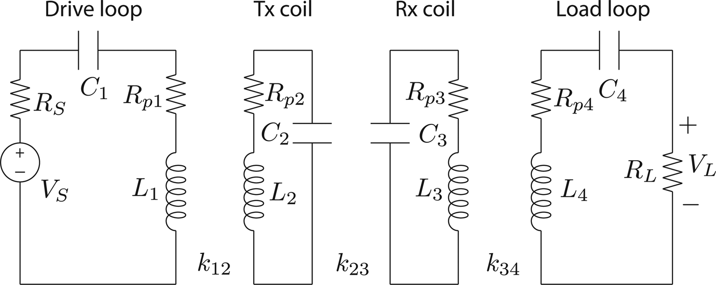
As a matter of fact, maximum power can be delivered under a resonance condition, but resonances are by nature narrowband, hence not suitable for data transmission, which is limited by bandwidth. This leads to a tradeoff in the design process of the proposed system, which can be well approached by an optimization procedure. In the following subsections, the symbols used refer to the common lumped parameters equivalent circuit of a four coils WPT system (as shown in Fig. 1) in which, besides source and load resistances R S and R L , the parasitic resistances R pi are shown, together with the coupling factors k ij .
Equivalent circuit of a four coils WPT system.

A) Design criteria for maximum power transfer
The maximum power transfer theorem is commonly used in WPT systems: maximum power transfer is achieved when the load impedance is the complex conjugate of the source impedance (
 $\bar Z_L = \bar Z_S^* $
). However, it should be noted that when maximum power transfer occurs (at impedance matching), the maximum system energy efficiency cannot exceed 50%; i.e. in the maximum power transfer regime, half of the power is dissipated in the source resistance R
S
(that usually must be very low), and on the stray resistance of the resonators. This circumstance is particularly hazardous for high-power systems because it can easily lead the system at overheating condition. As known, maximum power transfer is related to the scattering parameter
 $$S_{21} = 2\displaystyle{{V_L} \over {V_S}} \sqrt {\displaystyle{{R_S} \over {R_L}}}, $$
which is often measured or calculated: designing a system with the aim of maximizing S 21 is equivalent to imposing the maximum power transfer.
B) Design criteria for maximum energy efficiency
Maximum energy efficiency takes place when ohmic losses on the internal resistances are negligible with respect to the power delivered to the load resistance. This is well explained by equation (2)
 $$\eta = \displaystyle{{R_L I_L^2} \over {\sum\nolimits_i {R_{pi} I_i^2 + R_S I_S^2 + R_L I_L^2}}}, $$
in which I i are the currents and resistances in each loop (obviously I 1 = I S and I 4 = I L ). Any loss from stray resistances will decrease the energy efficiency and the main way to follow this goal would be to employ a power source with very low source resistance and low resistance coils (compared to the load resistance). As a rule of thumb, taking into account (1) should be necessary for low- and mid-power applications, while (2) is suitable for relatively high-power applications (see for instance [Reference Hui, Zhong and Lee27–Reference Sample, Meyer and Smith30]), even though it is correct to say that the choice between the strategy to be followed is strictly case-dependent. The working point of a WPT system is usually between the maximum efficiency, in terms of total input power delivered by the generator, and maximum power at the output port. Unfortunately, the working point at the maximum efficiency, in terms of total input power delivered by the generator, usually delivers a very low power at the output, limiting the performance of the system. We have designed the WPT link in order to achieve low transmission loss through the wireless channel and high power at the load. This can be obtained by maximizing the magnitude of the S 21 parameter of the coupled resonators system.
C) Selection between a two or four coils system for WPT
A constantly increasing literature is available in which comparisons between two coils and four coils systems are presented. The operating principle is the same in both cases (resonance and frequency splitting characterize both approaches), while the difference stands in the achievable transmission distance. In two coils, the energy efficiency depends on the coupling factor k between the two coils according to
 $$\eta = \displaystyle{{k^2} \over 2},$$
i.e. it rapidly drops with the increase of the distance between the coils. On the other hand, in a four coils system (composed by the excitation–pickup loops and the coupling inductors), it can be demonstrated that the power transfer can be maximized if the condition shown in (4) is met
 $$\displaystyle{{k_{12} k_{34}} \over {k_{23}}} = 1,$$
in which k 23 is the coupling coefficient between the inductors, while k 12 k 34 is the product between the coupling coefficients of the excitation/pickup loops and the nearest coupling inductors. The main objective of using a four coils system is that according to (4) k 23 can be reduced (higher distance) still retaining maximum power transfer.
D) PLC channel capacity calculation
The evaluation of the channel capacity of a PLC system is performed by the use of the Shannon–Hartley's law
 $$C = \int_0^B \log _2 \left( {1 + \displaystyle{{S(f)} \over {N(f)}}} \right)df,$$
in which C is the channel capacity in bits per second, B is the bandwidth of the channel, S(f) is the signal power spectrum, N(f) is the noise power spectrum, and f is the frequency. The signal power spectrum can be expressed as a function of the injected power spectrum and the transfer function, according to
 $$S(f) = \parallel H(f)\parallel ^2 S_I (f).$$
At the moment, the constructed prototype involves the coupled resonators, the matching capacitors, and the coupling filter. The following assumptions are made: both the injected power spectrum S I (f) = S I and the noise power spectrum N(f) = N are frequency-independent, while the noise is considered as Additive White Gaussian Noise, AWGN, at the receiver.
III. SYSTEM DESCRIPTION, IMPLEMENTATION, AND COIL CHARACTERIZATION
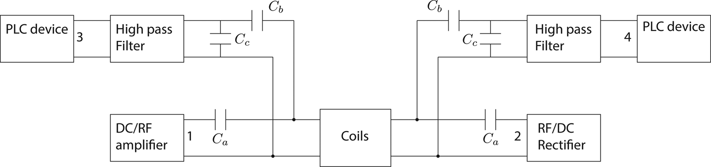
In order to achieve a correct PLC signal transmission and reception through the WPT coils system, the scheme shown in Fig. 2 is proposed. The coils are the core of the system and both data and power have to go through the magnetic coupling established between them. The lower part of Fig. 2 represents the usual WPT link in which a power amplifier (fed by the mains) sends a high power at an established frequency to the receiver, which is basically a rectifier and a load. The capacitor guarantees the tuning of the system in order to obtain the desired goal (efficiency, maximum power transfer). The upper part of Fig. 2 represents the PLC link in which the so-called PLC device can be either a PLC modem (fed by the mains) or the 50/60 Hz power grid with a PLC signal superimposed. The role of the high-pass filter and the capacitors C b , C c is the one usually performed by the capacitive coupler always present in PLC modems. In this particular case, the filter and the capacitors should not only guarantee an efficient coupling between the data signal and the power link but also give a frequency decoupling between power and data: the high-power/lower frequency signal of the WPT link should not interfere with the PLC devices (causing possible damages) and, at the same time, the high-frequency/low-power PLC signal should reach the coils. In particular, the capacitors C b and C c are used to improve the matching of the filtering stage to the coupled inductors. It is worth noting that, while the power transmission can be designed for being unidirectional (as shown in the figure), the proposed scheme allows a bidirectional communication. Indeed the PLC device connected to the load loop is enabled to transmit data, which will propagate in the same fashion from the receiver (Rx) coil to the transmitter (Tx) coil.
Schematic of the WPT–PLC system.

A) Coils design
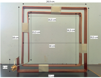
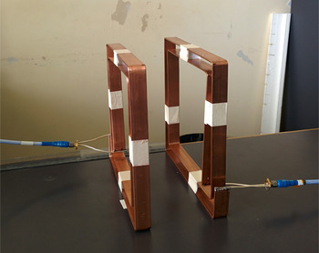
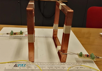
The system chosen for this application is composed of a couple of high Q mutually coupled inductors. This setup is the core of most of the inductive WPT systems and can be characterized quite easily. The choice for the experiment of a two coupling inductor system without excitation–pickup loops, allows one to estimate the performance of the system in terms of power transmission efficiency, considering that most of the power losses can be ascribed to the inductors wires themselves. Moreover, by adopting this configuration, the active part (power amplifier) of the WPT system can be directly connected to the coupling inductors by computing its conjugate image impedance [Reference Dionigi, Mongiardo and Perfetti31] to obtain optimal matching for the power signal. The two coupled inductors are made by a copper bar, with a cross-section of 2 × 20 mm, bended and shaped as illustrated in Figs 3 and 4. The inductance and Q factor of the inductors are, respectively, 1.37 μH and 105. The design criteria, as it is usual in WPT system, is to obtain a high Q factor and to achieve the desired coupling and resonance frequency (including the additional capacitors), by means of EM simulations.
Photo of the manufactured coil with quotes.

Photo of the setup measurements (distance between coils 10 cm).

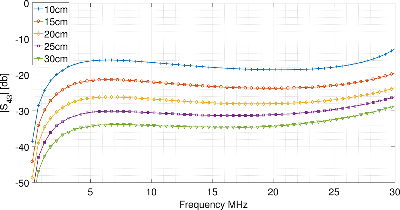
The coupled inductors of Figs 3 and 4 were connectorized (using SMA female panel adapters) and characterized, varying their distance (between 10 and 30 cm), by measuring the scattering matrix in the frequency range from 30 kHz to 30 MHz by the use of a vector network analyzer). Figure 5 shows the measured transmission coefficient of the coils, for the above mentioned different distances. In these measurements, only the coils constituted the device under test, and not any further equipment, as couplers or filters, was present in the measurement path. The measured scattering parameters of such system are used in the simulation software to implement the block called “coils” in the complete model of Fig. 2. As for the frequency operating point, it was decided to adopt the industrial, scientific and medical (ISM) band of 6.78 MHz as power transmission frequency, while the band [10, 30] MHz was reserved to the data signal. In this manner, two filtering stages can be added in order to isolate the data from the power channels according to the system shown in Fig. 2.
Transmission coefficient relative to the two coils system.
B) Filter and capacitors design
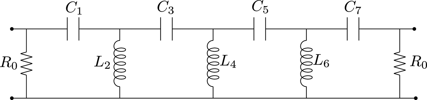
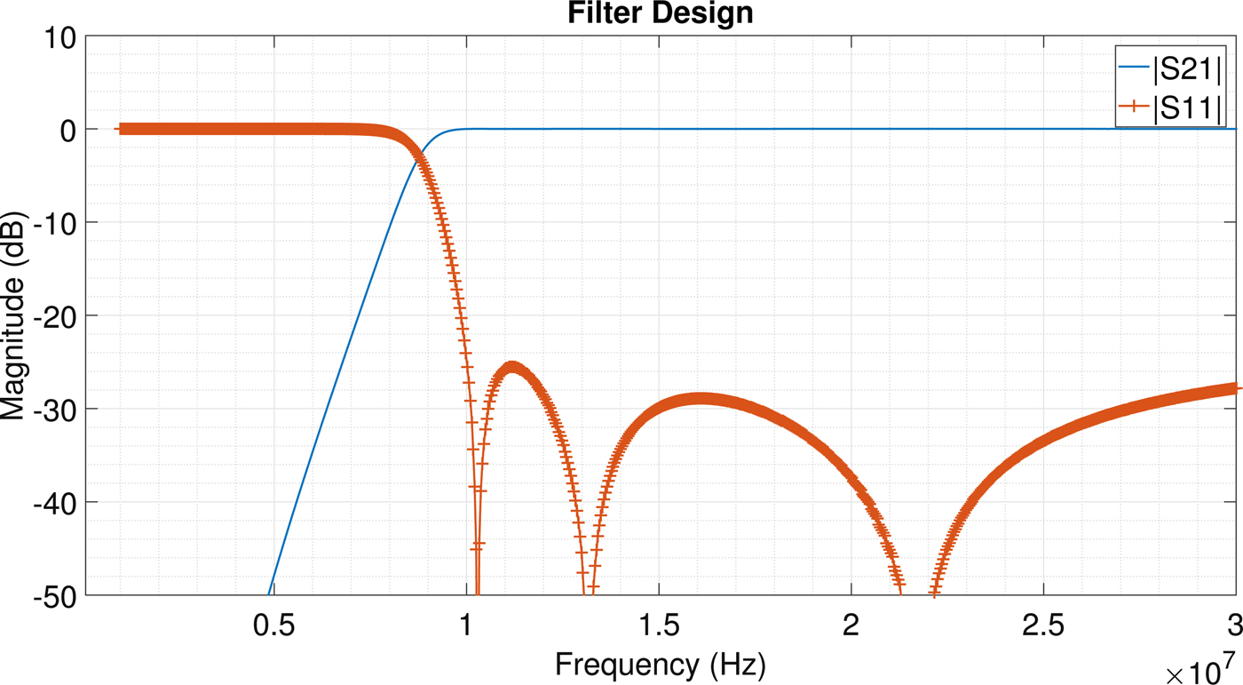
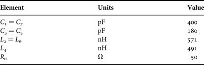
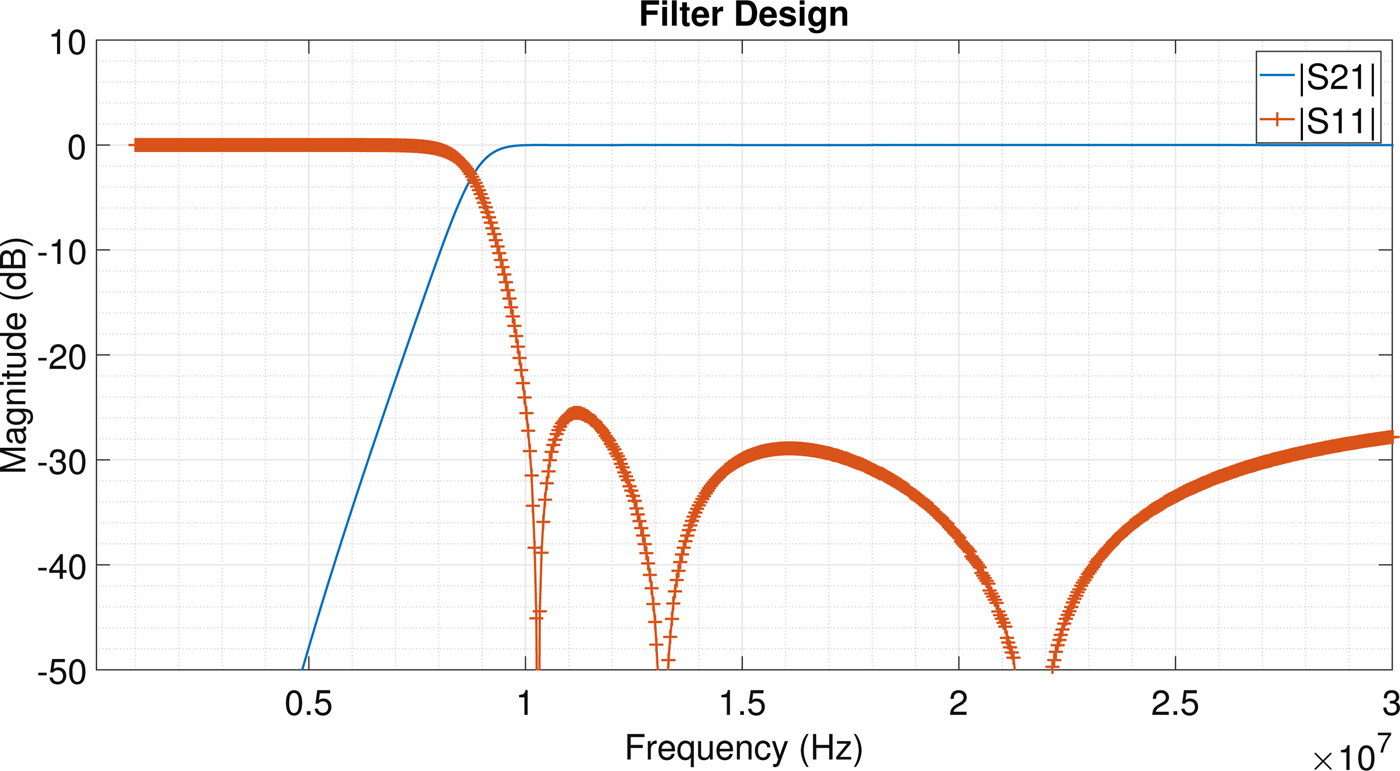
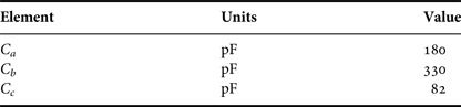
In a stand-alone WPT system, the capacitors are used to tune the power channel to the desired frequency; in this case, the presence of the filter causes a variation of the equivalent reactance seen from the coils terminations. For this reason, an optimization procedure in the circuit simulator Keysight ADS (http://www.keysight.com/en/pc-1297113/advanced-design-system-ads) is performed in order to obtain the desired tuning at the ISM frequency band. The first step has been to use two ideal Chebycheff high-pass filters; the cutoff frequency for these filters is 10 MHz (with a ripple of 1 dB); and an attenuation of 40 dB is chosen at 6 MHz (at the frequency of the power channel). Ports 1 and 2, shown in Fig. 2, are the input and output terminations for power channel, while ports 3 and 4 are those for power line data signal. The PLC devices (PLC modems) and the amplifier/rectifier are modeled with a 50Ω impedance. The filter was consequently synthesized and the result of this procedure is the seventh order Chebycheff filter shown in Fig. 6, whose parameters are shown in Table 1. Its frequency response (in the band [0, 30] MHz) is shown in Fig. 7.
Chebycheff filter of order seventh.

Frequency response of the designed filter.
Chebycheff filter parameters.

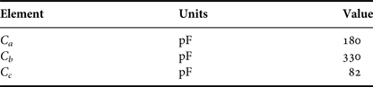
The filter was implemented with commercial components characterized by a 5% tolerance; in the next section, a Monte Carlo analysis relative to the tolerance effect on the performance of the whole system has been performed. In order to correctly design the WPT–PLC system also, the coupling capacitors have to be defined, with their fundamental role of tuning to the desired frequency, reducing the reactive power and allowing an efficient coupling between the PLC devices and coils. The resulting values of the capacitors are reported in Table 2.
Capacitors values.
The capacitors have also been implemented with 5% tolerance commercial elements. It is worth to underline that the design has been performed in order to optimize the system with the coils at a distance of 10 cm.
IV. SYSTEM PERFORMANCES
A) Power transfer section
According to the design process described in the previous section (based on the measurements performed on the coils and on the simulations on ADS), the system has been built and tested. The result is a full system, which includes the coils and the two coupling filters (Fig. 8). The power amplifier is not yet available and it will be included in further studies; however, the availability of the complete four ports systems let us measure the scattering parameters and the transfer function. Such measurements are not trivial since they basically show the real achievable power transfer efficiency and data channel capacity; the only parameter which is missing is the noise injected in the system by the power amplifier. For this reason, the assumption of AWGN at the receiver is taken.
Resonators system and filters during measurements.

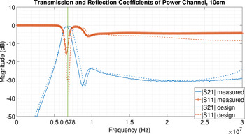
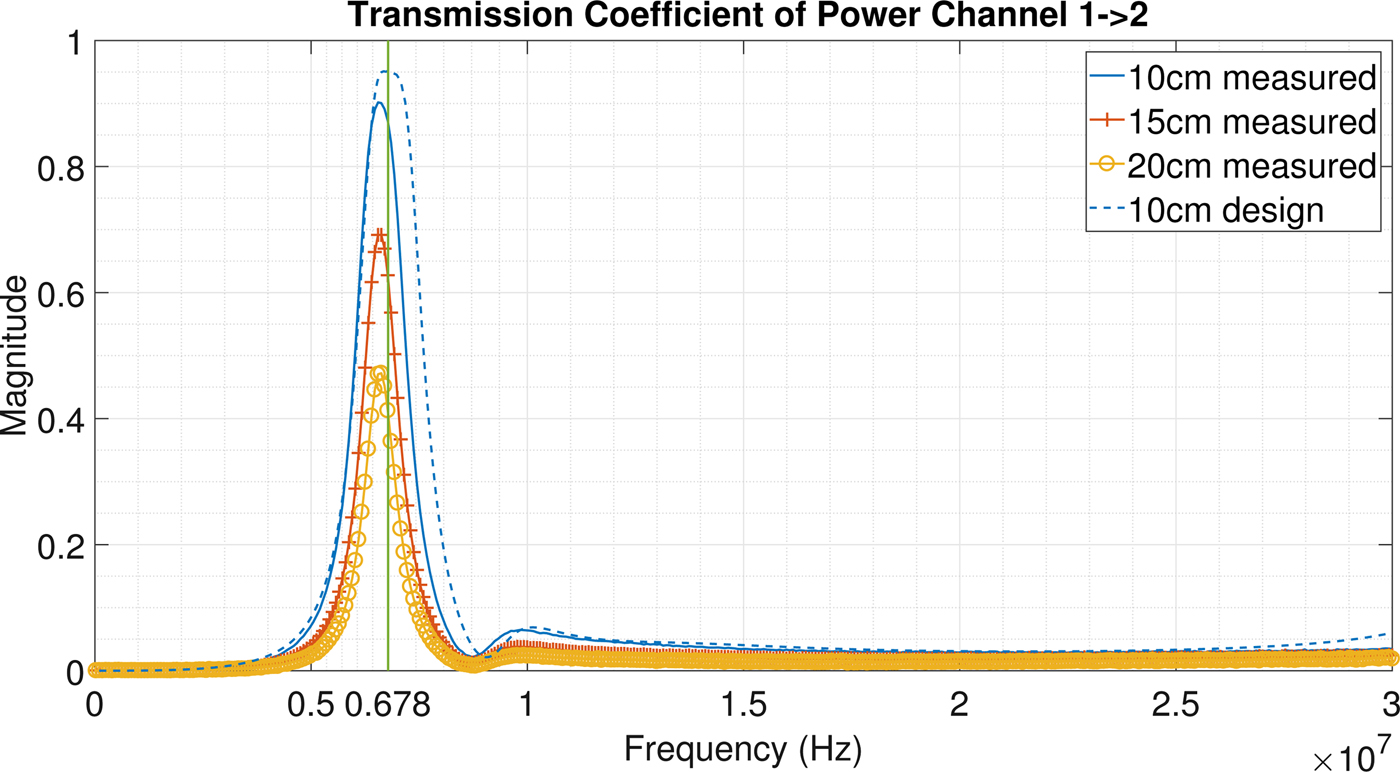
As for the power stage, the reflection and transmission coefficients at a distance of 10 cm (the design situation) are shown in Fig. 9, obtained both by simulations and measurements. The good agreement between the results is clear. The frequency chosen for power transmission (6.78 MHz) is evidenced with a green line to verify the transmission efficiency of the system; in Fig. 10, the transmission coefficients are shown in a linear scale: it can be verified that at the chosen ISM frequency, the design transmission coefficient is equal to about 0.95 corresponding to a power transfer efficiency of about 90% calculated as |S 21|2. The measured curve shows a slight decrease in the power transfer efficiency (|S 21| = 0.9) still retaining very good performances. In Fig. 10 also measurements at higher distances are reported, showing a decrease of the performances (as expected). It is worth noticing, however, that the peak efficiency is always obtained at the design frequency.
Reflection and transmission coefficients on the power channel (ISM frequency band 6.78 MHz ± 15 KHz).

Transmission coefficient on the power line channel (linear scale). The transmission efficiency of the link is about 90%.
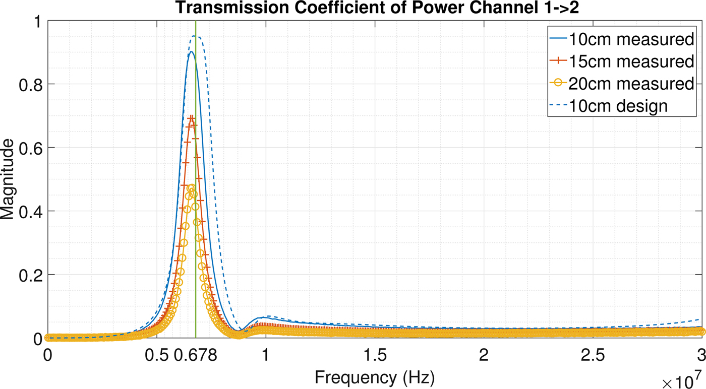
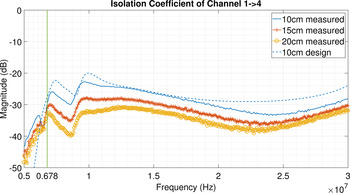
Figure 11 shows the isolation between the input port of the power channel (port 1) and the output port of the power line data channel (port 2). In this case also, the performance of the system is very satisfactory; in fact the isolation in both cases is better than −30 dB (at 6.78 MHz). For the sake of conciseness, the isolation between ports 1 and 3 is not shown; however, the isolation at the power band shows the same value of −30 dB. It is worth mentioning that the achieved isolation is important in order not to damage the PLC modem with high voltages from the power amplifier. Higher harmonics introduced by the power amplifier are filtered out by the system itself (as shown in Fig. 11 for frequencies higher than the resonant one) and, at this stage of the research, this is sufficient to say that the actual study is accurate.
Isolation among the input port of the power channel and output port of the power line data channel. At the frequency of 6.78 MHz, the parameters are better than −30 dB.

The parameter that mainly influences the performance of the WPT system is the coupling coefficient between the two inductors. In order to maintain the same coupling coefficient, even varying the distance between the two coupled inductors, the ratio between the dimension of the inductor and the distance has to be kept constant; thinking about a system for EV battery charging, the distances analyzed in this contributions are reasonable. Further study will be dedicated to the evaluation of the channel's sensitivity as a function of small distance variations, which could be caused, for instance, by different tires pressure or dampers status.
B) Data transfer section
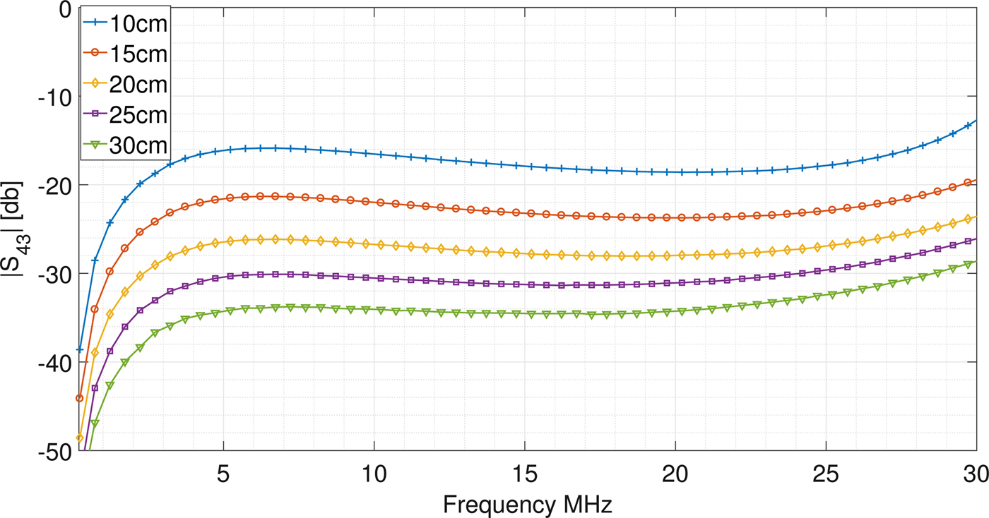
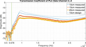
The data channel performances at different distances of the coils have been evaluated and shown in Fig. 12: it is clear that a distance increase leads to the reduction of the coupling coefficient, hence to the performance decay of the data transfer system. The attenuation obtained at a 10 cm distance (at which the system has been optimized) is more than reasonable to achieve a wide band data transmission, as it is shown later.
Transmission coefficient on the power line data channel in the frequency range [2, 30] MHz at different distances.

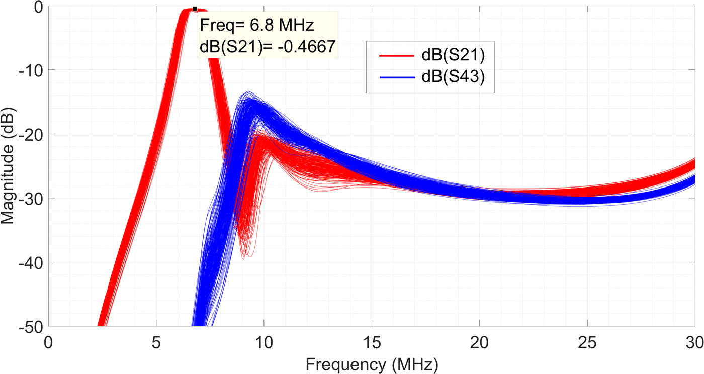
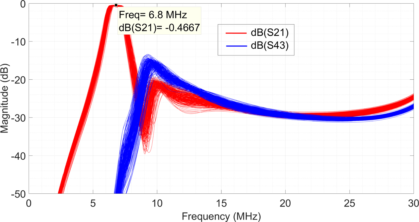
As previously mentioned, Fig. 13 shows the result of a Monte Carlo analysis performed to evaluate the effect of a 5% tolerance on the components, which does not substantially affect the system's performance.
Scattering parameters relative to the power and data ports: effect on the components’ tolerance obtained by a standard Monte Carlo set of simulations.
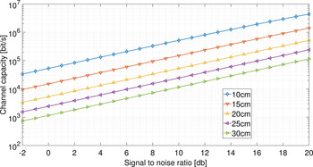
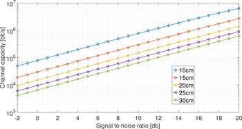
The theoretical channel capacity of the power line data channel was evaluated using equation 5; Fig. 14 shows the channel capacity in the [8, 30] MHz frequency band (most commonly used for actual standards) calculated for the whole set of distances. The SNR is calculated using the injected signal power density, and it varies between 2 and 20 dB. Analyzing the theoretical channel capacity values for a distance of 10 cm, values between 33.5 kbit/s and 4.4 Mbit/s are obtained. Looking at higher distances, these values decrease down to the range 0.9 kbit/s to 0.1 Mbit/s. As a result, a fairly good data link is observed also in the case of highly noisy scenarios. The attenuation of the channel between 15 and 30 MHz is almost constant, with a value around −30 dB, which is a typical attenuation value of PLC channels. Under these conditions, it is reasonable to expect that a PLC modem will provide a data rate that approximates the average PLC performance in a typical PLC channel. It is worth to note that in general PLC channels are affected by strong time variations of the frequency response, while in this case the channel is expected to be stationary. The same simulations have been performed also using the extended frequency band up to 40 MHz. At a distance of 10 cm, the so obtained theoretical channel capacity is now between 50.2 kbit/s and 6.4 Mbit/s, which degrades down to 4 kbit/s to 0.6 Mbit/s at a distance of 30 cm (Fig. 15). Using the larger band up to 40 MHz provides a constant gain of almost 2 dB in SNR with respect to the band up to 30 MHz, to obtain the same channel capacity. On the other hand, for a fixed SNR value, the capacity increases to 150%. This is also due to the peak of the frequency response at 33 MHz, which can be observed in the transfer functions.
Channel capacity in the frequency band 2–30 MHz at different coils distances.

Channel capacity in the frequency band 2–40 MHz at different coils distances.

V. CONCLUSION
In this paper, a combined coupled resonators wireless system for power and data transmission is proposed. A two coils system has been designed, built, and measured showing good agreement with the design parameters. The system frequency characteristics allow both an efficient power transmission in the ISM frequency band and a satisfactory data transmission capacity in the bands having upper limits of either 30 or 40 MHz.
As a general result, the coexistence of a narrowband channel for power transfer, and a broadband channel for data transfer, using the same coils, is possible thanks to a four-port design, which is both straightforward to design and cost-effective. This allows two existing technologies, WPT and PLC, to share the same medium, with a minimum modification of the existing components and electronics, leading to a new paradigm, that we can name power channel communications.
FINANCIAL SUPPORT
This research received no specific grant from any funding agency, commercial or not-for-profit sectors.
STATEMENT OF INTEREST
None.
 Sami Barmada received the M.S. and Ph.D. degrees in Electrical Engineering from the University of Pisa, Italy, in 1995 and 2001, respectively. He currently is a Full Professor with the Department of Energy and System Engineering (DESTEC), University of Pisa. His teaching activity is related to circuit theory and electromagnetics. His research activity is mainly dedicated to applied electromagnetics, power line communications, non-destructive testing and signal processing. He is an author and coauthor of approximately 100 papers in international journals and refereed conferences. Prof. Barmada was the recipient of the 2003 J. F. Alcock Memorial Prize, presented by the Institution of Mechanical Engineering, Railway Division, for the Best Paper in Technical Innovation; he is a IEEE Senior Member and ACES Fellow. He served as ACES President from 2015 to 2017 and now he is a member of the International Steering Committee of the CEFC Conference.
 Marco Dionigi received the Ph.D. degree in Electronic Engineering from the University of Perugia, Perugia, Italy, in 1996. He is currently an Assistant Professor with the Department of Electronic and Information Engineering, University of Perugia. His current research interests are in the field of microwave and millimeter-wave waveguide component modeling and optimization, wireless power transfer systems and modeling, microwave sensor modeling and design, and microwave and ultrawideband system design.
 Paolo Mezzanotte received the Ph.D. degree from the University of Perugia, Italy, in 1997. Since January 2007, he is an Associate Professor with the same University, teaching the classes of Radiofrequency Engineering. His research activities concern numerical methods and CAD techniques for passive microwave structures and the analysis and design of microwave and millimeter-wave circuits. More recently, his research interests were mainly focused on the study of advanced technologies such as LTCC, RF-MEMS, and microwave circuits printed on green substrates. These research activities are testified by more than 100 publications in the most important specialized journals and at the main conferences of the microwave scientific community.
 Mauro Tucci received the Ph.D. degree in Applied Electromagnetism from the University of Pisa, Pisa, Italy, in 2008. Currently, he is an Associate Professor at the Department of Energy and Systems Engineering, University of Pisa, Pisa, Italy. His research activity is in machine learning, data analysis, and system identification, with applications in electromagnetism, non-destructive testing, and power-line communications.