1. Introduction
Load-carrying is one of the important activities in human life, which has been concerned by researchers. Studies have shown that the kinematics, kinetics, plantar pressure and energy expenditure of the human are all affected when walking with a heavy load [Reference Liew, Morris and Netto1–Reference Vickery-Howe, Drain, Clarke, Dascombe, McWilliam and Middleton3]. With the increase of the load, the spatio-temporal proportion of the support phase in gait, the lower limb joint moment, the plantar pressure, and the energy metabolism all increase [Reference Seay4, Reference Walsh and Low5]. The changes make the human body extremely prone to fatigue, which in turn can trigger the risk of injury or illness.
To assist human load-carrying, researchers have developed a series of auxiliary equipment. Improving the backpack device to redistribute the load on the upper limbs can reduce the stress on the lower limbs, which has limited effectiveness and can easily increase metabolic energy [Reference Park, Jin and Agrawal6, Reference Park, Stegall, Zhang and Agrawal7]. Powered load-carrying exoskeleton (PLE) can transfer the load to the ground for support and joint assistance. However, PLEs generally require external energy and drive devices, which greatly limit their usage scenarios due to large self-weight and short endurance [Reference Gregorczyk, Hasselquist, Schiffman, Bensel, Obusek and Gutekunst8–Reference Zoss, Kazerooni and Chu10]. Flexible joint exoskeletons have a small self-weight and can assist joint moment, but due to the lack of a rigid lower limb structure, they do not have a support assistance function [Reference Mooney and Herr11, Reference Panizzolo, Galiana, Asbeck, Siviy, Schmidt, Holt and Walsh12]. Supernumerary limb robot has a support structure independent of human legs, which can effectively assist in supporting the load [Reference Zhan, Zhang, Hou, Kang, Dai and Song13, Reference Zhang, Zhan, Ju, Hou, Kang, Dai and Song14]. However, the coordination between the supernumerary limbs and the human legs is difficult to implement [Reference Hao, Zhang, Chen, Asada and Fu15, Reference Liao, Chen, Chang, Zheng, Liu and Lv16]. The unpowered load-carrying exoskeleton (ULE) transfers the load to the ground for support assistance by rigid structure, and recovers the energy for joint moment assistance through elastic components or lightweight hydraulic systems [Reference Fan, Dai, Zhang, He, Pan, Yi and Liu17, Reference Kong, Koh, Ho, Iskandar and Lim18]. Because there is no external energy or driving device, ULE has the characteristics of light-weight and long-endurance [Reference Walsh, Endo and Herr19, Reference Wei, Zhang and Zhang20].
While ULE provides a new idea for human load-carrying assistance, its design still faces two important challenges. One challenge is gait adaptability. There are many methods for dividing human gait in current exoskeleton research. When the foot is not considered, the support phase is divided into the single-support and double-support phases [Reference Lim and Park21–Reference Whittington and Thelen23]. Because the feet are not considered, this gait is not applicable to ULE. When the feet are considered, papers [Reference Aoustin and Formalskii24–Reference Kazerooni, Racine, Huang and Steger26] subdivide the single-support and double-support phases according to the contact conditions between the foot and ground, and ignore the stage when the heel of one foot and the toe of the other are in contact with the ground at the same time. In this stage, both feet are not in full contact with the ground, and the spatio-temporal proportion of this stage in the gait cycle increases with the increase of load [Reference Huang and Kuo27]. This stage can be neglected in PLE because the human joint moments can be compensated by external energy. However, ULE is completely driven by the human lower limbs. Ignoring this stage will cause the loss of key information, such as motion and force between the foot and ground, resulting in a significant impact of elastic elements on human gait. Ultimately, the effect of support and joint moment assistance can not meet expectations. Previous studies indicate that the motion between the foot and ground can be considered as rolling around specific pivots [Reference Hansen, Childress and Knox28, Reference Levens, Inman and Blosser29]. From the heel touching the ground, the foot rolls forward around the heel pivot, ankle pivot (ankle joint), forefoot pivot (metatarsophalangeal joint) and toe pivot in turn. Based on this, a variable pivot gait (VPG) is proposed in our previous study [Reference Ai, Wei, Zhang, Song, Lv and Liu30]. This gait contains the stage when the heel of one foot and the toe of the other are in contact with the ground at the same time, which can completely describe the actual situation of contact conditions between the foot and ground.
Another challenge is the design of assistance principle. Push-off plays a crucial role in normal human walking gait [Reference Doerks, Riedel, Einfeldt, Windhagen, Hurschler and Jakubowitz31, Reference Winter32]. Direct assist to the ankle joint by elastic elements during the push-off has always been a focus of unpowered assisting walking exoskeletons [Reference Collins, Wiggin and Sawicki33, Reference Wang, Guo, Qu, Song and Qu34]. However, there are no cases of applying this method to ULE. Papers [Reference Soo and Donelan35, Reference Zelik, Takahashi and Sawicki36] point out that there is a coordination between the ankle push-off of the following leg and the heel collision of the guiding leg during walking. When the push-off work decreases, the collision work needs to be increased to achieve the reorientation of the body centroid speed during the step-to-step transition.
The main contribution of this paper is that, based on VPG, a double-leg coordination assistance principle for load-carrying is proposed: assisting support of the guiding leg to reduce the collision to reduce the ankle moment of the following leg that is performing the push-off. Meanwhile, a novel ULE with a double-support closed-chain configuration is designed, and the assistance principle is verified by experiments for assisting and energy-saving effect evaluation.
The paper is organized as follows: In Section 2, the corresponding gait stages of push-off and collision in VPG are determined through human load-carrying experiments, and an assisting principle for load-carrying is proposed. Based on the principle, a novel ULE with a double-support closed-chain configuration is designed, and relevant theories are verified. In Section 3, load-carrying experiments are conducted with 0, 5, 10, 15 and 20 kg load, respectively, under the three conditions of without ULE, wearing ULE without spring and with spring. In Section 4, the plantar pressure, spring compression, angle and moment of human joints during the experiment are analyzed. In Section 5, metabolic cost experiment and result analysis are conducted with 0, 5, 10, 15 and 20 kg load under the three conditions. Sections 6 and 7 are discussion and conclusion, respectively.
2. Assistance principle, configuration design and dynamics analysis of the novel ULE
2.1. Assistance principle for load-carrying
The kinematics of the human lower limbs with a 10 kg load is shown in Figure 1. The analysis indicates that the heel of one foot (heel-pivot stage, 0–15%) and the toe of the other (toe-pivot stage, 50–65%) are in contact with the ground synchronously. The heel-pivot stage mainly performs collision function, while the toe-pivot stage mainly performs push-off function.
Kinematic parameters of human low limb with 10 kg load. The foot angle was the angle between the hindfoot and the ground at normal walking speed(cadence, 60 steps/min). Data shown were trajectories averaged across subjects (N = 5).

The human VPG model is shown in Figure 2 when collision and push-off functions are considered. The single-leg (red rod) support phase of the human body is subdivided into: double-support heel-pivot stage, single-support ankle-pivot stage, single-support forefoot-pivot stage and double-support toe-pivot stage. Based on VPG, the assistance principle for load-carrying is proposed as follows: (1) Double-support phase, assisting support of the guiding leg at the heel-pivot stage, directly reducing the force on the lower limb during heel collision, assisting the reorientation of the load centroid, thus reducing the ankle joint moment of the following leg that is performing the push-off function at the toe-pivot stage; (2) Single-support phase, the load of the support leg is transferred to the ground for support and joint moment assistance.
Variable pivot gait considering collision and push-off.

2.2. Design of ULE with a double-support closed-chain configuration
Based on the assistance principle, a novel ULE with a double-support closed-chain configuration is proposed, which is shown in Figure 3. The ULE consists of a symmetrical left and right closed-chain support mechanism and a backpack. The two closed-chain support mechanisms are connected to the backpack through an abductor joint, as shown in Figure 3(a). As shown in Figure 3(b), the unilateral closed-chain support mechanism has 3 freedoms, which are composed of the anterior and posterior branch chains connected through the connecting bars and the luggage carriers. The anterior branch chain is bound to the human thigh, shank and foot, which is driven by the human hip, knee and ankle joints. As shown in Figure 3(c), the posterior branch chain has two rotational joints, and there is a prismatic joint arranged with a linear spring at the support bar, and the length regulator makes the ULE adapt to the heights of humans from 1680 to 1850 mm. The ULE worn by the human body is shown in Figure 4, with an overall weight (including the backpack) of 5 kg.
The novel unpowered load-carrying exoskeleton (ULE). (a) 3D model. (b) Double-supported closed-chain mechanism. (c) Design of length regulator, rotational and prismatic joints.

ULE wearing. (a–c) Front, side and rear views of ULE wearing.

The working principle of ULE is shown in Figure 5, which can achieve both support and joint moment assistance during the whole support phase. Joint moment assistance: (1) Double-support phase, when the heel of the right leg marked in red contacts the ground, the spring contacts the ground in advance, converting the collision energy loss into elastic potential energy, thus reducing the energy required for the left leg in the toe-pivot stage to push off the ground and reducing the ankle joint moment as shown in Figure 5(a) and (d); (2) Single-support phase, the posterior branch chain releases the spring force to assist the support leg joint moments as shown in Figure 5(b) and (c). Support assistance: during the whole support phase, when the human foot is in contact with the ground, ULE transfers the load to the ground through the anterior and posterior branch chains to achieve support assistance.
Principle of ULE. Right leg (marked in red): (a) Heel-pivot stage, support assistance. (b, c) Ankle-pivot and forefoot-pivot stages, support and joint moment assistance. (d) Toe-pivot stage, joint moment assistance.

2.3. Kinematics and dynamics analysis
The heel-pivot, ankle-pivot, forefoot-pivot and toe-pivot stages of unilateral ULE are analyzed, respectively. The closed vector method is used for kinematics calculation, and the Lagrange equations of the second kind are used to calculate the hip, knee and ankle moments required to drive the ULE with or without spring.
Unilateral ULE simplified model is displayed as Figure 6. θ 1, θ 2, θ 3 and θ 0 are the angles of human ankle joint, knee joint, hip joint and foot-ground, respectively. θ and θ 4 are constants related to the size of the mechanism. q 5, q 6, q 7 and q 8 are the angles between the corresponding bar and the vertical direction, respectively. The positive and negative definitions of angles are marked in Figure 6. A 0 is the origin of the coordinate system. l g is the distance from heel to ankle, and l q is the distance from the ankle to the forefoot-pivot or toe-pivot. l i is the length of each bar, a i is the distance of the centroid, i = 1, 2, 3,…, 8; meanwhile, l 2 = l 6, l 3 = l 5, l 4 = l 7 = l 8.
Unilateral ULE simplified model. (a) Heel-pivot and ankle-pivot stage model. (b) Forefoot-pivot and toe-pivot stage model.

2.3.1. Kinematics analysis
Kinematic analysis of parallelogram A 2 A 3 B 4 B 5 and A 0 A 1 B 6 B can be obtained:
 \begin{equation} \left[\begin{array}{l} q_{1}\\ q_{2}\\ q_{3}\\ q_{4}\\ q_{5}\\ q_{6}\\ q_{7}\\ q_{8} \end{array}\right]=\left[\begin{array}{llllll} 1 &\quad 0 &\quad 0 &\quad 0 &\quad 0 &\quad 0\\ 1 &\quad -1 &\quad 0 &\quad 0 &\quad 0 &\quad 0\\ 1 &\quad -1 &\quad 1 &\quad 0 &\quad 0 &\quad 0\\ 1 &\quad -1 &\quad 1 &\quad -1 &\quad 1 &\quad 0\\ 1 &\quad -1 &\quad 1 &\quad 0 &\quad 0 &\quad 0\\ 1 &\quad -1 &\quad 0 &\quad 0 &\quad 0 &\quad 0\\ 1 &\quad -1 &\quad 1 &\quad -1 &\quad 0 &\quad 1\\ 1 &\quad -1 &\quad 1 &\quad -1 &\quad 0 &\quad 1 \end{array}\right]\left[\begin{array}{l} \theta _{0}\\ \theta _{1}\\ \theta _{2}\\ \theta _{3}\\ \begin{array}{l} \theta _{4}\\ \theta \end{array} \end{array}\right] \end{equation}
The l c change represents the compression of the spring inside the support bar. The spring compression Δl can be obtained:
 \begin{align}& l_{c}=\frac{l_{g}\sin \theta _{0}+l_{1}\cos \theta _{0}+l_{8}\cos \left(\theta +\theta _{0}{-}\theta _{1}+\theta _{2}{-}\theta _{3}\right)}{\cos \left(\theta _{0}{-}\theta _{1}\right)} \end{align}
 \begin{align}&\qquad\qquad\qquad\qquad {\unicode[Arial]{x0394}} l=l_{c}{-}l_{c0} \end{align}
In Eq. (3), l c0 and l c are the original and real-time length of the support bar, respectively.
The coordinates of the centroid of each bar during support phase are obtained:
 \begin{equation} \left[\begin{array}{l} x_{1}\\ x_{2}\\ x_{3}\\ x_{4}\\ x_{5}\\ x_{6}\\ x_{7}\\ x_{8} \end{array}\right]=\left[\begin{array}{llllllll} a &\quad 0 &\quad 0 &\quad 0 &\quad 0 &\quad 0 &\quad 0 &\quad 0\\ b &\quad -l_{1} &\quad -a_{2} &\quad 0 &\quad 0 &\quad 0 &\quad 0 &\quad 0\\ b &\quad -l_{1} &\quad -l_{2} &\quad -a_{3} &\quad 0 &\quad 0 &\quad 0 &\quad 0\\ b &\quad -l_{1} &\quad -l_{2} &\quad -l_{3} &\quad -a_{4} &\quad 0 &\quad 0 &\quad 0\\ b &\quad -l_{1} &\quad -l_{2} &\quad 0 &\quad 0 &\quad -a_{5} &\quad 0 &\quad -l_{7}\\ b &\quad -l_{1} &\quad 0 &\quad 0 &\quad 0 &\quad 0 &\quad -a_{6} &\quad -l_{8}\\ b &\quad -l_{1} &\quad -l_{2} &\quad 0 &\quad 0 &\quad 0 &\quad 0 &\quad -a_{7}\\ b &\quad -l_{1} &\quad 0 &\quad 0 &\quad 0 &\quad 0 &\quad 0 &\quad -a_{8} \end{array}\right]\left[\begin{array}{c} \cos \theta _{0}\\ \sin \theta _{0}\\ \sin \left(\theta _{0}-\theta _{1}\right)\\ \sin \left(\theta _{0}-\theta _{1}+\theta _{2}\right)\\ \sin \left(\theta _{0}-\theta _{1}+\theta _{2}-\theta _{3}+\theta _{4}\right)\\ \sin \left(\theta _{0}-\theta _{1}+\theta _{2}\right)\\ \sin \left(\theta _{0}-\theta _{1}\right)\\ \sin \left(\theta _{0}-\theta _{1}+\theta _{2}-\theta _{3}+\theta \right) \end{array}\right] \end{equation}
 \begin{equation} \left[\begin{array}{l} y_{1}\\ y_{2}\\ y_{3}\\ y_{4}\\ y_{5}\\ y_{6}\\ y_{7}\\ y_{8} \end{array}\right]=\left[\begin{array}{llllllll} a &\quad 0 &\quad 0 &\quad 0 &\quad 0 &\quad 0 &\quad 0 &\quad 0\\ b &\quad l_{1} &\quad a_{2} &\quad 0 &\quad 0 &\quad 0 &\quad 0 &\quad 0\\ b &\quad l_{1} &\quad l_{2} &\quad a_{3} &\quad 0 &\quad 0 &\quad 0 &\quad 0\\ b &\quad l_{1} &\quad l_{2} &\quad l_{3} &\quad a_{4} &\quad 0 &\quad 0 &\quad 0\\ b &\quad l_{1} &\quad l_{2} &\quad 0 &\quad 0 &\quad a_{5} &\quad 0 &\quad l_{7}\\ b &\quad l_{1} &\quad 0 &\quad 0 &\quad 0 &\quad 0 &\quad a_{6} &\quad l_{8}\\ b &\quad l_{1} &\quad l_{2} &\quad 0 &\quad 0 &\quad 0 &\quad 0 &\quad a_{7}\\ b &\quad l_{1} &\quad 0 &\quad 0 &\quad 0 &\quad 0 &\quad 0 &\quad a_{8} \end{array}\right]\left[\begin{array}{c} \sin \theta _{0}\\ \cos \theta _{0}\\ \cos \left(\theta _{0}-\theta _{1}\right)\\ \cos \left(\theta _{0}-\theta _{1}+\theta _{2}\right)\\ \cos \left(\theta _{0}-\theta _{1}+\theta _{2}-\theta _{3}+\theta _{4}\right)\\ \cos \left(\theta _{0}-\theta _{1}+\theta _{2}\right)\\ \cos \left(\theta _{0}-\theta _{1}\right)\\ \cos \left(\theta _{0}-\theta _{1}+\theta _{2}-\theta _{3}+\theta \right) \end{array}\right] \end{equation}
In Eqs. (4) and (5), during heel-pivot and ankle-pivot stage, a = a 1, b = l g ; during forefoot-pivot and toe-pivot stage, a = -a 1, b = -l q .
2.3.2. Dynamics analysis
As shown in Figure 6, T 1, T 2 and T 3 are the drive moments of the anterior branch chain, and T 0 is the moment required between the foot and the ground. Taking θ 0, θ 1, θ 2 and θ 3 as generalized coordinates, the total kinetic energy and potential energy of the system are expressed as follows:
 \begin{align}& K=\frac{1}{2}\sum _{i=1}^{8}\left[I_{i}{\dot{q}_{i}}^{2}+m_{i}\left({\dot{x}_{i}}^{2}+{\dot{y}_{i}}^{2}\right)\right] \end{align}
 \begin{align}&\qquad P=\sum _{i=1}^{8}m_{i}gy_{i}+\frac{1}{2}k{\unicode[Arial]{x0394}} l^{2} \end{align}
 $\dot{q}_{i}$
is the absolute angular velocity of each bar to the ground, I
i
is the rotational inertia, m
i
is the mass,
 $\dot{x}_{i}$
and
 $\dot{y}_{i}$
are the velocities of the centroid, n = 8. g is the acceleration of gravity and k is the spring stiffness.
The Lagrange function of the human lower limbs system is defined as follows:
 \begin{align}&\qquad L=K-P \end{align}
 \begin{align}& T_{i}=\frac{d}{dt}\left[\frac{\partial L}{\partial \dot{\theta }_{i}}\right]-\frac{\partial L}{\partial \theta _{i}} \end{align}
2.3.3. Kinematics and dynamics calculation results
Assuming that ULE does not interfere with the motion of the human with load-carrying, the joint angle of the human lower limbs in Figure 1 is used as the motion input of the ULE for dynamics calculation. The principles for determining ULE scale parameters are as follows: (1) the bar length is based on the human at 1710 mm refer to ref. [Reference Ho, Shiang, Lee and Cheng37]; (2) the spring stiffness k = 2 N/mm is determined by the principle that the posterior branch chain shares half of the load when the human body is standing static. l 4= l 7= l 8 = 180 mm, l c0 = 170 mm.
As shown in Figure 7(a) and (d), the spring has a significant assistance on the ankle moment at both the ankle-pivot and forefoot-pivot stages of unilateral ULE. Meanwhile, the spring also has a certain assisting effect on the knee and hip joints, as shown in Figure 7(b) and (c). The assisting effect of the combined action of both legs needs to be measured by load-carrying experiment.
Joint moments and spring compression of ULE at support phase. (a–c) Hip, knee and ankle moments required to drive ULE with and without spring. (d) Spring compression.

3. Load-carrying experiments
3.1. Experiment and measurement protocols
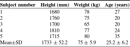
We conducted load-carrying experiments on 5 healthy subjects under three conditions: without ULE (WU), wearing ULE without spring (UOS), and wearing ULE with spring (UWS). These conditions are shown in Figure 8, respectively. All subjects received explanations about the nature and possible consequences of the experiments before their participation. The study was approved by the Biomedical Ethics Committee of Hebei University of Technology in Tianjin, China. The ethics protocol number: HEBUTHMEC2025040. Table I lists the details of the 5 male subjects (N = 5).
Load-carrying experiments for assisting effect evaluation. (a) Without ULE (WU). (b) Wearing ULE without spring (UOS). (c) Wearing ULE with spring (UWS).

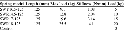
The experiment protocol was separated into training and testing. In the training, the subjects under each condition with 4 loads (5, 10, 15 and 20 kg) walked on the ground, respectively. With the metronome, each training cadence was 60 steps/min, and the time was 5 min. In the testing, each subject under each condition with 4 loads (5, 10, 15 and 20 kg) walked on the force platforms at 60 steps/min cadence per trial. The criterion for the success of per trial: the left leg steps onto the first force platform, the right foot steps onto the second force platform and then the left leg steps onto the third force platform. The 8 results of a load test under each condition are averaged. When ULE was worn with a spring, the spring parameters corresponding to each load were shown in Table II, in which 0 kg without spring is the control group.
Motions were measured by a reflective marker motion capture system (10 cameras, Nokov, Beijing Metrology Technology Co., Ltd., China; 100 Hz). The reflective balls were placed according to the 39-point rule of 2392 human model, as referred to in ref. [Reference Hoy, Zajac and Gordon38]. Reflective balls at the joint position were easily obscured by the exoskeleton; therefore, 1 cm reflective balls were used, and 1.5 cm reflective balls were used for the rest positions, as shown in Figure 9(c) and (d). In addition, the reflective balls are arranged at the prismatic joint at both ends of the support bar to obtain the spring compression.
Pressure insole and marks. (a) Pressure insoles with bluetooth receiver. (b) Pressure insoles arrangement. (c) 1.5 reflective balls. (d) 1 cm reflective balls.

The total ground reaction force of the human and ULE was measured by 3 force platforms (AMTI, Watertown, MA, USA; 90*60 cm; 100 Hz). When the human was wearing ULE, the plantar pressure of the human was collected by the pressure insole (RX-ES42-18, CROWNTO, Luoyang crown extension electronic Co., Ltd., China) as shown in Figure 9(a) and (b).
Parameters of 5 subjects.

3.2. Experiment data processing and analysis
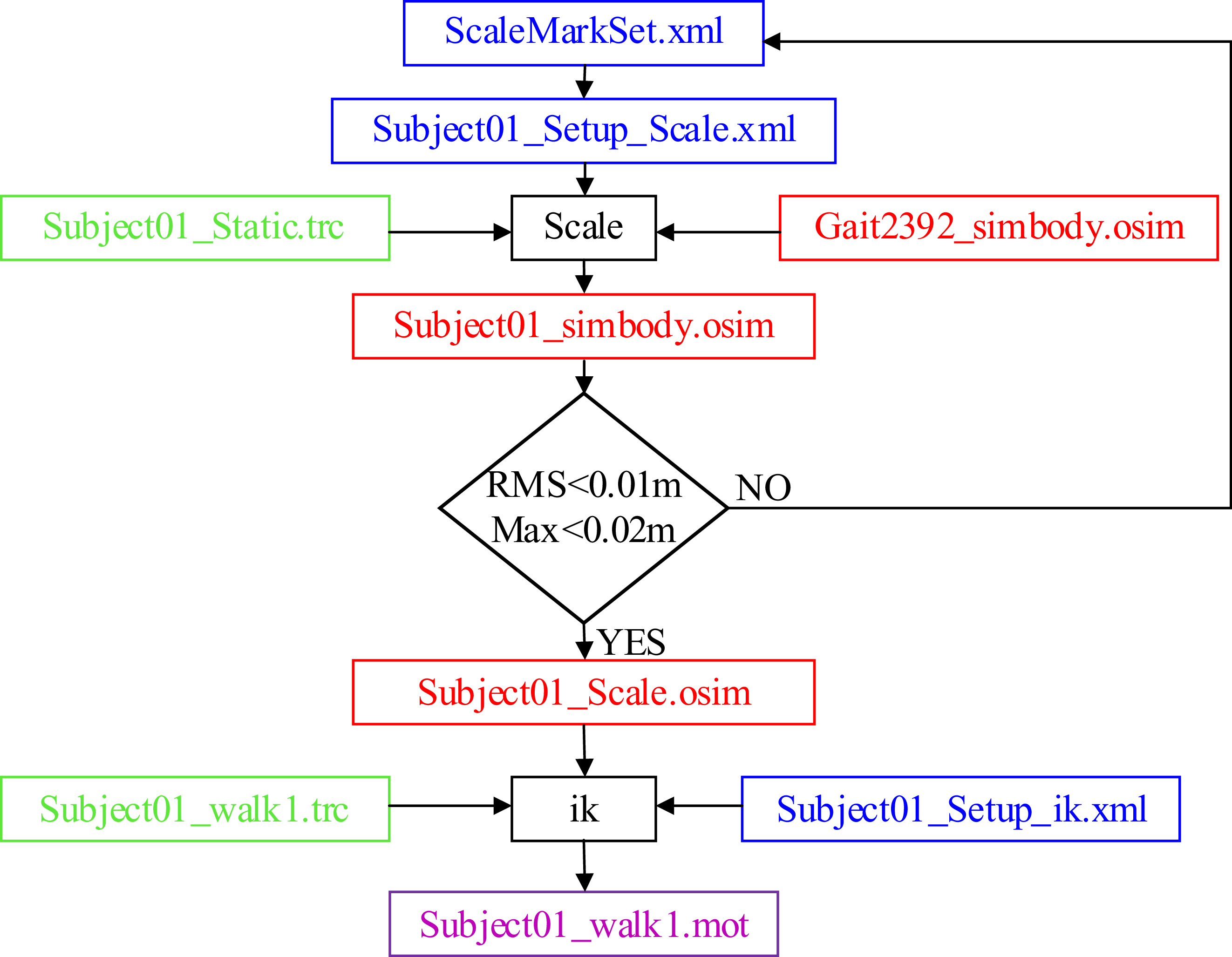
Human body scaling must be performed based on each subject’s static data before inverse kinematics (IK), ensuring subsequent motion data can be used for calculations according to the subjects’ actual body parameters. First, MATLAB (MATLAB 2018b, Mathworks, USA) converts the static C3D-format human body data collected in the static experiment into TRC-format. Then, the converted TRC static data, virtual marker setting file and scaling setting file are imported based on OpenSim (OpenSim4.2, Stanford University, USA) standard Gait2392 model. Finally, OpenSim scaling tool adjusts the corresponding virtual markers in the Gait2392 model from bottom to top, prioritizing positions with the largest errors between experimental and virtual markers. Human body scaling is completed when the maximum error of bone markers is less than 2 cm and the root mean square error (RMS) is less than 1 cm, the human body scaling is completed.
Spring parameters corresponding to each load.

After scaling the human body model, exoskeleton rod lengths are adjusted according to human bone joint feature dimensions. Using Notepad++(Version 7.4.2, Kim JongDaehyun, ROK) for programing, each rod is imported into the scaled Gait2392 model to generate a human–machine coupling model corresponding to each subject wearing the exoskeleton. Following scaling, OpenSim IK algorithm solves the human–machine IK problem, converting motion marker data from the human–machine loaded motion capture experiment into actual lower limb joint angles. The scaling and IK process is illustrated in Figure 10.
Scaling and inverse kinematics process.

The scaling and IK were calculated by OpenSim software to obtain the angles of human lower limb joints [Reference Delp, Anderson, Arnold, Loan and Thelen39, Reference Falisse, Serrancolí, Dembia, Gillis and Groote40]. The calculation of joint moments in the sagittal plane was based on the human–machine coupling model developed by OpenSim, as shown in Figure 11. The Moco algorithm module in OpenSim was used to track the joint motions and plantar forces collected in the experiment [Reference Antonie, Blana and Dieter41, Reference De Groote, Kinney, Rao and Fregly42], and the joint moments of the human lower limbs were obtained through MATLAB programing and calculation.
OpenSim human–machine coupling simulation model. (a) Without ULE (WU). (b) Wearing ULE without spring (UOS). (c) Wearing ULE with spring (UWS).

The average and standard deviations of human plantar pressure, spring compression, angle and moment of human lower limb joints were calculated (N = 5) for each load under the three conditions. Meanwhile, statistical analysis was performed using GraphPad Prism (version 9.5, GraphPad Software, San Diego, California, USA). The peak, averages during whole stride and support phase of the joint moments (hip, knee and ankle) and plantar pressure for each load under the three conditions were analyzed by one-way repeated measures analysis of variance (ANOVA). Furthermore, the Bonferroni post hoc test was performed to determine the level of significant difference between conditions and verify support and joint moment assistance of ULE.
4. Results of load-carrying experiments for assisting effect evaluation
4.1. Joint kinematics
The kinematics results of the human carrying 5 loads (0, 5, 10, 15 and 20 kg), respectively, under the three conditions are shown in Figure 12. As shown in Figure 12(a), (f) and (k), UOS with 0 kg load has little impact on human lower limb motions. With the increase of load, the spatiotemporal proportion of the double support phase (heel-pivot and toe-pivot stages) in the gait cycle and the ankle plantarflexion angle in the toe-pivot stage increase continuously. Meanwhile, UWS can effectively reduce the ankle plantarflexion angle compared with WU in the toe-pivot stage, as shown in Figure 12(k−o). In addition, with the load increasing, the impact of UOS on human motions increases, as shown in Figure 12(e), (j) and (o).
Hip, knee and ankle joint angles. (a–e) Hip joint angles, (f–j) knee joint angles, and (k-o) ankle joint angles. Data shown are trajectories averaged across subjects (N = 5), and shadows represent standard deviation (SD).

4.2. Joint moments
4.2.1. Ankle, knee and hip joint moments with 5 kg load
With 5 kg load, the trajectories of ankle, knee and hip moments in three conditions are shown in Figure 13(a), (e) and (i). The trends of the ankle moments among three conditions are almost the same, as shown in Figure 13(a). After the ANOVA test for WU, UOS and UWS as shown in Figure 13(b–d). The average ankle moments over the whole stride and support phase of the three conditions show significant differences (p = 0.008, p = 0.008). Bonferroni post-hoc test shows that both the average ankle moment over the whole stride and support phase can be reduced in the UWS compared with WU (post-hoc test, p = 0.04, p = 0.05). The peak ankle moment of the three conditions showed a significant difference (p < 0.001), which can be reduced in the UWS compared with WU (post-hoc test, p = 0.005).
Ankle, knee and hip joint moments with 5 kg load. (a, e and i) Trajectories of ankle, knee and hip joint moments averaged across subjects (N = 5), and shadows represent standard deviation (SD). (b, c) Average ankle moments over the whole stride and support phase. (d) Peak ankle moment. (f, g) Average knee moments over the whole stride and support phase. (h) Peak knee moment. (j, k) Average hip moments over the whole stride and support phase. (l) Peak hip moment. *Significant difference at p < 0.05, **significant difference at p < 0.01, ***significant difference at p < 0.001; error bars, SD; support phase, 0–63% stride; all the joint moments were normalized to subject body mass.

The ANOVA results also show that UWS has little effect on knee moment, as shown in Figure 13(f–h). Compared with WU, the average knee moments over the whole stride and support phase (post-hoc test, p > 0.99, p > 0.99), and the peak knee moment (post-hoc test, p > 0.99) of UWS have no significant difference. However, compared with WU, the average knee moments over the whole stride and support phase (post-hoc test, p < 0.001, p = 0.01), and the peak knee moment (post-hoc test, p = 0.03) of UOS show that knee moment is increased. As shown in Figure 13(j-l), compared with WU, the hip moment is reduced significantly in UWS, especially the peak hip moment (post-hoc test, p = 0.04).
4.2.2. Ankle, knee and hip joint moments with 10 kg load
With 10 kg load, the trajectories of ankle, knee and hip moments in three conditions are shown in Figure 14(a), (e) and (i). The trends of the ankle moments among the three conditions are almost the same as shown in Figure 14(a). After the ANOVA test for WU, UOS and UWS, as shown in Figure 14(b–d). The average ankle moments over the whole stride and support phase of the three conditions show significant differences (p < 0.001, p = 0.001). Bonferroni post-hoc test shows that both the average ankle moment over the whole stride and support phase can be reduced in UWS compared with WU (post-hoc test, p = 0.005, p = 0.01). The peak ankle moment of the three conditions showed a significant difference (p = 0.002), which can be reduced in the UWS compared with WU (post-hoc test, p = 0.005).
Ankle, knee and hip joint moments with 10 kg load. (a–j) The meaning of the content in each figure is the same as that in Figure13. Support phase, 0–65% stride.

The ANOVA results also show that UWS has little effect on knee moment, as shown in Figure 14(f–h). Compared with WU, the average knee moments over the whole stride and support phase (post-hoc test, p = 0.53, p > 0.99), and the peak knee moment (post-hoc test, p = 0.15) of UWS have no significant difference. However, compared with WU, the average knee moment over the support phase and the peak knee moment (post-hoc test, p = 0.01, p = 0.02) of UOS show that knee moment is increased. As shown in Figure 14(j−l), compared with WU, the hip moment is reduced significantly in UWS, especially the peak hip moment (post-hoc test, p = 0.02).
4.2.3. Ankle, knee and hip joint moments with 15 kg load
With 15 kg load, the trajectories of ankle, knee and hip moments in three conditions are shown in Figure 15(a), (e) and (i). The trends of the ankle moments among the three conditions are almost the same as shown in Figure 15(a). After the ANOVA test for WU, UOS and UWS, as shown in Figure 15(b–d). The average ankle moments over the whole stride and support phase of the three conditions show significant differences (p = 0.009, p < 0.001). Bonferroni post-hoc test shows that both the average ankle moment over the whole stride and support phase can be reduced in the UWS compared with WU (post-hoc test, p = 0.02, p = 0.001). The peak ankle moment of the three conditions showed a significant difference (p < 0.001), which can be reduced in the UWS compared with WU (post-hoc test, p < 0.001).
Ankle, knee and hip joint moments with 15 kg load. (a–j) The meaning of the content in each figure is the same as that in Figure 13. Support phase, 0–66% stride.

The ANOVA results also show that UWS has little effect on knee moment, as shown in Figure 15(f–h). Compared with WU, the average knee moments over the whole stride and support phase (post-hoc test, p = 0.2, p = 0.72), and the peak knee moment (post-hoc test, p = 0.06) of UWS have no significant difference. However, compared with WU, the average knee moment over the support phase and the peak knee moment (post-hoc test, p = 0.01, p = 0.02) of UOS show that the knee moment is increased. As shown in Figure 15(j−l), compared with WU, the hip moment is reduced significantly in UWS, especially the peak hip moment (post-hoc test, p = 0.07).
4.2.4. Ankle, knee and hip joint moments with 20 kg load
With 20 kg load, the trajectories of ankle, knee and hip moments in three conditions are shown in Figure 16(a), (e) and (i). The trends of the ankle moments among the three conditions are almost the same as shown in Figure 16(a). After the ANOVA test for WU, UOS and UWS, as shown in Figure 16(b–d). The average ankle moments over the whole stride and support phase of the three conditions show significant differences (p < 0.001, p = 0.03). Bonferroni post-hoc test shows that both the average ankle moment over the whole stride and support phase can be reduced in the UWS compared with WU (post-hoc test, p < 0.001, p = 0.004). The peak ankle moment of the three conditions showed a significant difference (p = 0.004), which can be reduced in the UWS compared with WU (post-hoc test, p < 0.001).
Ankle, knee and hip joint moments with 20 kg load. (a–j) The meaning of the content in each figure is the same as that in Figure 13. Support phase, 0–68% stride.

The ANOVA results also show that UWS has little effect on knee moment, as shown in Figure 16(f–h). Compared with WU, the average knee moments over the whole stride and support phase (post-hoc test, p = 0.93, p > 0.99), and the peak knee moment (post-hoc test, p = 0.08) of UWS have no significant difference. However, compared with WU, the average knee moment over the support phase and the peak knee moment (post-hoc test, p = 0.001, p = 0.005) of UOS show that the knee moment is increased. As shown in Figure 16(j−l), compared with WU, the hip moment is reduced significantly in UWS, especially the peak hip moment (post-hoc test, p = 0.03).
4.3. Plantar pressure and spring compression
4.3.1. Plantar pressure and spring compression with 5 kg load
With 5 kg load, a similar trend can be observed from the vertical ground reaction forces among three conditions, as shown in Figure 17(a). Compared with WU, the vertical ground reaction force is reduced in UWS, especially during the heel-pivot and toe-pivot stages. As shown in Figure 17(d), during the ankle-pivot stage, the spring is under maximum compression. However, during the toe-pivot stage, the spring is released. The ANOVA is performed for three conditions as shown in Figure 17(b) and (c). The average over the whole stride and peak vertical ground forces of three conditions show significant differences (p = 0.001, p = 0.002). Bonferroni post-hoc test shows that the average over the whole stride and the peak vertical ground forces can be reduced in the UWS compared with WU (post-hoc test, p = 0.003, p = 0.02).
Plantar pressure and spring compression with 5 kg load. (a,d) Trajectories of vertical ground reaction forces and spring compression averaged across subjects (N = 5), and shadows represent standard deviation (SD). (b,c) Average over the whole stride and peak vertical ground reaction force. *Significant difference at p < 0.05, **significant difference at p < 0.01, ***significant difference at p < 0.001; error bars, SD; all the force data were normalized to subject body mass; the spring data are normalized to subject body height.

4.3.2. Plantar pressure and spring compression with 5 kg load
With 10 kg load, a similar trend can be observed from the vertical ground reaction forces among three conditions, as shown in Figure 18(a). Compared with WU, the vertical ground reaction force is reduced in UWS, especially during the heel-pivot and toe-pivot stages. As shown in Figure 18(d), during the ankle-pivot stage, the spring is under maximum compression. However, during the toe-pivot stage, the spring is released. The ANOVA is performed for three conditions as shown in Figure 18(b) and (c). The average over the whole stride and peak vertical ground forces of three conditions show significant differences (p = 0.004, p = 0.001). Bonferroni post-hoc test shows that the average over the whole stride and the peak vertical ground forces can be reduced in the UWS compared with WU (post-hoc test, p < 0.001, p = 0.009).
Plantar pressure and spring compression with 10 kg load. (a–d) The meaning of the content in each figure is the same as that in Figure 17.

4.3.3. Plantar pressure and spring compression with 15 kg load
With 15 kg load, a similar trend can be observed from the vertical ground reaction forces among three conditions, as shown in Figure 19(a). Compared with WU, the vertical ground reaction force is reduced in UWS, especially during the heel-pivot and toe-pivot stages. As shown in Figure 19(d), during the ankle-pivot stage, the spring is under maximum compression. However, during the toe-pivot stage, the spring is released. The ANOVA is performed for three conditions as shown in Figure 19(b) and (c). The average over the whole stride and peak vertical ground forces of three conditions show significant differences (p < 0.001, p < 0.001). Bonferroni post-hoc test shows that the average over the whole stride and the peak vertical ground forces can be reduced in the UWS compared with WU (post-hoc test, p = 0.004, p = 0.004).
Plantar pressure and spring compression with 15 kg load. (a–d) The meaning of the content in each figure is the same as that in Figure 17.

4.3.4. Plantar pressure and spring compression with 20 kg load
With 20 kg load, a similar trend can be observed from the vertical ground reaction forces among three conditions, as shown in Figure 20(a). Compared with WU, the vertical ground reaction force is reduced in UWS, especially during the heel-pivot and toe-pivot stages. As shown in Figure 20(d), during the ankle-pivot stage, the spring is under maximum compression. However, during the toe-pivot stage, the spring is released. The ANOVA is performed for three conditions as shown in Figure 20(b) and (c). The average over the whole stride and peak vertical ground forces of three conditions show significant differences (p < 0.001, p < 0.001). Bonferroni post-hoc test shows that the average over the whole stride and the peak vertical ground forces can be reduced in the UWS compared with WU (post-hoc test, p < 0.001, p < 0.001).
Plantar pressure and springcompression with 20 kg load. (a–d) The meaning of the content in each figure is the same as that in Figure 17.

5. Metabolic cost experiment and result analysis
5.1. Metabolic cost experiment protocols
We conducted metabolic cost experiments on 5 healthy subjects carrying 5 loads (0, 5, 10, 15 and 20 kg) under three conditions, as shown in Figure 21. All subjects received explanations about the nature and possible consequences of the experiments before their participation. The study was approved by the Biomedical Ethics Committee of Hebei University of Technology. The ethics protocol number: HEBUTHMEC2025040.
Metabolic cost experiments. (a) WU. (b) UOS. (c) UWS.

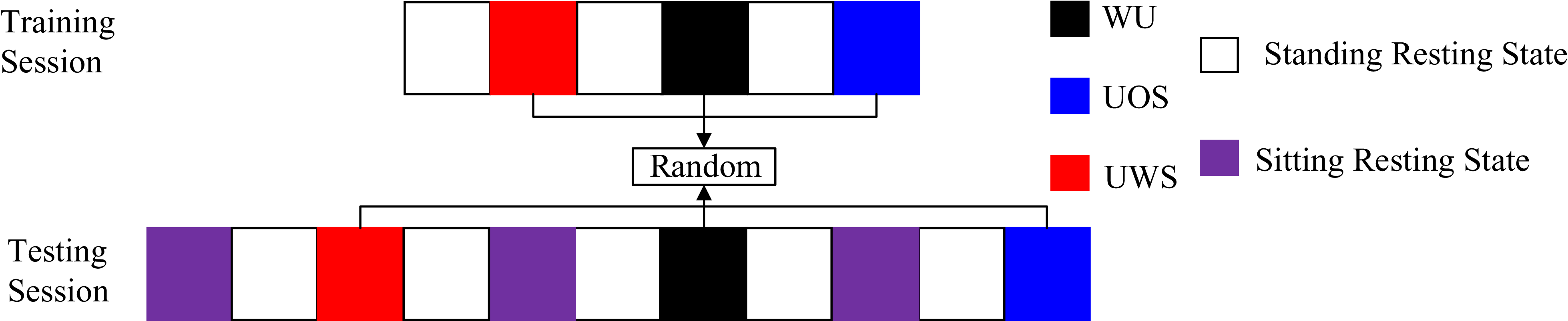
The experiment consists of training and testing processes. All subjects, well-rested, must follow the training and testing processes. Colored squares denote different stages, each lasting 6 min, with stage descriptions provided in Figure 22. With the metronome, training and testing cadence were 60 steps/min, and the wearing condition of the exoskeleton and the load were randomly selected. During training, each subject completed 2 training sessions for each exoskeleton-wearing condition with each load. During testing, each subject completed 3 training sessions for each exoskeleton-wearing condition with each load. Each session should have a 20-min rest interval.
Metabolic cost experiment protocol.

The site plan and field experiment are shown in Figure 23. During the experiment, a security guard held a metronome to supervise the gait cadence of the subjects while also ensuring safety protection. The operator was responsible for the overall experiment process and data recording.
Site plan and field experiment.

The respiratory metabolic data of the subjects were collected using the cardiopulmonary exercise testing System (Oxycon Mobile, CareFusion, California, USA), as shown in Figure 24. Metabolic rate was estimated from average rates of oxygen consumption (VO2) and carbon dioxide production (VCO2) during the last 2 min in each experiment stage using a standard formula [Reference Westenskow, Schipke, Raymond, Saffle, Becker, Young and Cutler43]. The metabolic rate during standing resting was subtracted from gross metabolic rate to get the net value attributable to the energetic demands of load-carrying under different exoskeleton-wearing conditions. Net metabolic rate values were then normalized to subject body mass.
The cardiopulmonary exercise testing system.

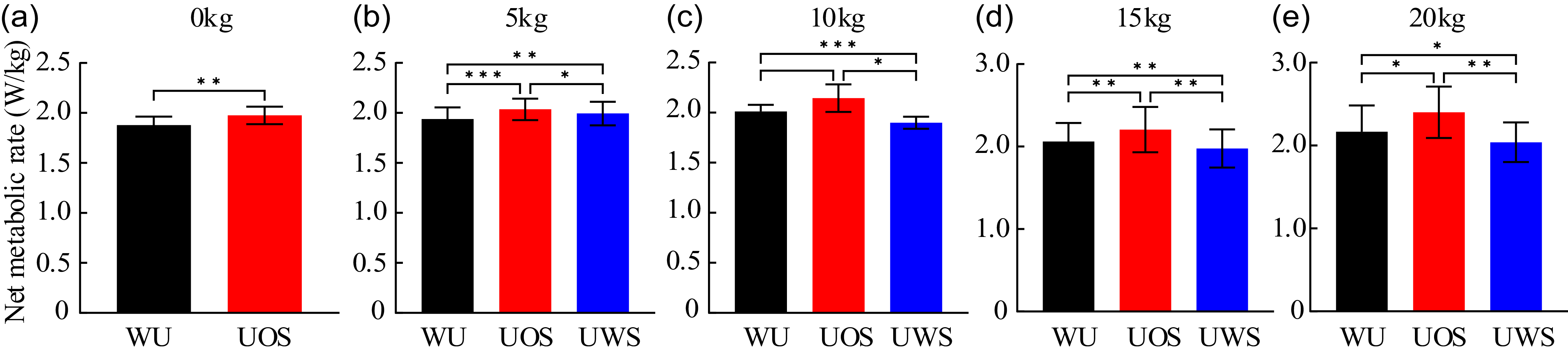
The average and standard deviations of net metabolic rate values were calculated (N = 5) for each load under the three conditions. We used two-tailed paired t-test to compare the conditions of WU and UOS to identify the impact of ULE weight on human energy with 0 kg load. The average net metabolic rate values for each load (5, 10, 15, and 20 kg) under the three conditions were analyzed by one-way repeated measures ANOVA. Furthermore, the Bonferroni post hoc test was performed to determine the level of significant difference between conditions and verify the energy-saving effect of ULE with spring.
5.2. Results of metabolic cost experiments for energy-saving effect evaluation
With 0 kg load, compared with WU, the net metabolic rate is increased in UOS by 5.2 ± 1% (Mean ±SE, two-tailed paired t-test, p = 0.007), as shown in Figure 25(a). With 5 kg load, the ANOVA is performed for three conditions as shown in Figure 25(b). The net metabolic rates of three conditions show significant differences (p < 0.001). Bonferroni post-hoc test shows that the net metabolic rate is increased by 2.9 ± 0.5% (Mean±SE) in the UWS compared with WU (post-hoc test, p = 0.007). With 10 kg load, the ANOVA is performed for three conditions as shown in Figure 25(c). The net metabolic rates of three conditions show significant differences (p = 0.01). Bonferroni post-hoc test shows that the net metabolic rate is reduced by 5.6 ± 0.5% (Mean±SE) in the UWS compared with WU (post-hoc test, p < 0.001). With 15 kg load, the ANOVA is performed for three conditions as shown in Figure 25(d). The net metabolic rates of three conditions show significant differences (p < 0.001). Bonferroni post-hoc test shows that the net metabolic rate is reduced by 4.1 ± 0.7% (Mean±SE) in the UWS compared with WU (post-hoc test, p = 0.005). With 20 kg load, the ANOVA is performed for three conditions as shown in Figure 25(d). The net metabolic rates of three conditions show significant differences (p < 0.001). Bonferroni post-hoc test shows that the net metabolic rate is reduced by 5.9 ± 1.6% (Mean±SE) in the UWS compared with WU (post-hoc test, p = 0.04).
Net metabolic rate under the three conditions. (a–e) Net metabolic rate of 0–20 kg load. *Significant difference at p < 0.05, ** significant difference at p < 0.01, *** significant difference at p < 0.001; error bars, SD; all net metabolic rates were normalized to subject body mass.

6. Discussion
Previous studies show that with the increase of the load, the spatiotemporal proportion of the double-support phase (heel-pivot and toe-pivot stages) in the gait cycle will also increase [Reference Huang and Kuo27], which is verified in the experiment of this paper. With 0, 5, 10, 15 and 20 kg load, the spatiotemporal proportions are 24%, 26%, 30%, 32% and 36%, respectively (Figure 14). The result shows that it is important to pay attention to the load-carrying assistance during the double-support phase. Meanwhile, the kinematics analysis also shows that wearing ULE with spring to carry load has less interference on human low limb motions.
In terms of joint moment assistance, compared with carrying 5, 10, 15 and 20 kg load by the human alone, wearing ULE with spring reduces the human average ankle moment over support phase by 36.8 ± 9.1%, 23.6 ± 3.9%, 33.4 ± 2.9% and 27.8 ± 3.4%, the peak ankle moment by 11.9 ± 1.6%, 11.2 ± 1.5%, 11.8 ± 1% and 8.7 ± 0.6% and the peak hip moment by 34.6 ± 8.2%, 14.3 ± 2.9%, 25.9 ± 5.6% and 33.3 ± 4.8% (Mean±SE), respectively. During the double-support phase, the peak hip moment is at the heel-pivot stage, and the peak ankle moment is at the toe-pivot stage. The reductions of the two peak moments indicate that wearing ULE with spring can provide joint moment assistance to the hip during collision execution and ankle during push-off execution. Furthermore, the reduction of average ankle moment over the whole support phase is greater than the peak reduction, indicating that wearing ULE with spring can also perform joint moment assistance to the ankle in the single-support phase.
In terms of support assistance, compared with carrying 5, 10, 15 and 20 kg load by the human alone, wearing ULE with spring reduces the human average vertical plantar pressure over the whole stride by 6.4 ± 0.7%, 7.2 ± 0.4%, 8.1 ± 1% and 6.1 ± 0.5%, the peak vertical plantar pressure by 3.7 ± 0.5%, 2.8 ± 0.4%, 3.8 ± 0.5% and 5.2 ± 0.3% (Mean±SE), respectively. During the double-support phase, the two peak vertical plantar pressures are at the beginning of the ankle-pivot and the toe-pivot stages. The reductions of the two peak vertical plantar pressures indicate that the posterior branch chain can perform support assistance during collision and push-off executions. Furthermore, compared with carrying load by the human alone, wearing ULE with spring reduces the average vertical plantar pressure over the whole support phase, indicating that ULE with spring can also perform support assistance in the single-support phase.
The analysis of the verification experiment results on the exoskeleton assisting effect shows that, compared with direct assistance to push-off of the following leg [Reference Collins, Wiggin and Sawicki33, Reference Wang, Guo, Qu, Song and Qu34], the support assistance of the guiding leg by the spring can reduce the collision, and then joint moment assistance can also be applied to the ankle moment of the following leg that is performing the push-off. Moreover, the ankle moment during the single-support phase is also reduced. One reason is that the support assistance of the posterior branch chain reduces the load bearing of human lower limbs; the other reason is that during the process from compression to release of the spring in the posterior branch chain, a forward force is generated on the anterior branch chain tightly bound to the human leg.
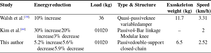
The analysis of the verification experiment results on the exoskeleton energy-saving effect results shows that, compared with the existing open-chain single-support lower limb exoskeletons [Reference Kim, Lim, Kim and Han44], the closed-chain double-support configuration of ULE results in a lighter self-weight, and it exhibits better energy-saving performance when carrying heavy loads, as shown in Table III.
Comparison of the energy reductions of different passive load-carrying exoskeletons.

7. Conclusion
Based on the characteristics of the VPG during human load-carrying, this paper proposes a double-leg coordination principle for load-carrying assistance: assisting support of the guiding leg at the heel-pivot stage by the spring to reduce the collision, which can reduce the ankle moment of the following leg that is performing the push-off at the toe-pivot stage. A novel ULE with a double-support closed-chain configuration is designed. The results of experiments show that, during the double-support phase, ULE with spring can provide support assistance to the guiding leg and joint moment assistance to the ankle of the following leg; during the single-support phase, the process from compression to release of the spring in the posterior branch chain can also provide assistance to ankle moment of the supporting leg. Moreover, ULE with spring can perform support assistance over the whole support phase.
The metabolic cost experiment results show that ULE reduces human net metabolic rate under 10, 15 and 20 kg loads while providing joint moment and support assistance. Notably, no such reduction was observed with a 5 kg load, indicating a potential correlation among load, spring stiffness and energy consumption reduction – a focus for subsequent research. This study can also be applied to the powered exoskeleton for load-carrying assistance, providing a new avenue.
Author contribution
Jianjun ZHANG was in charge of the whole research; Cunjin AI wrote the manuscript and Jun WEI assisted with the analysis and validation. The remaining discussed and read the manuscript. All authors read and approved the final manuscript.
Financial support
This research work was supported by the National Natural Science Foundation of China Grant No.52405015, China Postdoctoral Science Foundation Funded Project No.2024M760729, the Central Government guides basic research projects of local science and Technology Development Funds Grant No.236Z1814G and the Scientific and Technological Program of Chongqing Municipal Education Commission Grant No.KJQN202401340.
Competing interests
The authors declare no conflicts of interest exist.
Ethical approval
The study was approved by the Biomedical Ethics Committee of Hebei University of Technology in Tianjin, China. The ethics protocol number: HEBUTHMEC2025040.