I. INTRODUCTION
Dielectric microstrip antennas, due to their small size, high radiation efficiency, and ease of excitation, have received much attention in recent microwave telecommunications.Reference Singh1, Reference Zhou, Wu, Wang, Jiang and Yao2 The important characteristics required for a dielectric material used in microstrip antennas are: (i) high quality factor to achieve high radiation efficiency since the quality factor is representative of the antenna losses. Typically, there are radiation, conduction, dielectric, and surface wave losses. Since the dielectric microstrip antenna has a very low dielectric loss and has no metallic loss, it offers very high radiation efficiency; (ii) high dielectric constant (ε r) to reduce the size of the antenna because the wavelength (λ) in a dielectric is inversely proportional to  of the wavelength (λ 0) in vacuum (
 ); and (iii) near-zero temperature coefficient of resonant frequency (τ f) for high temperature stability.Reference Chen, Huang and Lo3–Reference Wu, Chen, Chen, Chou and Tsai5
ZnTiO3-based ceramics was one of materials suitable for the applications at microwave frequencies because of its high Qf value and low sintering temperature (1100 °C).Reference Kim, Byun and Kim6, Reference Kim, Byun and Kim7 But as reported by Kim et al.,Reference Kim, Byun and Kim6, Reference Kim, Byun and Kim7 ZnTiO3 would decompose to TiO2 and cubic Zn2TiO4 at above 945 °C which has a rather low quality factor. According to their report, single-phase ZnTiO3 can be successfully synthesized by applying a sol–gel process and a semichemical route combined with vigorous milling using zirconia beads. Adding glass–sol or B2O3 is useful to enhance sinterability of it. The microwave dielectric properties of the specimens sintered at 875 °C with B2O3 (0.5 wt%) additions were: ε = 29–31, Qf = 56,000–69,000 GHz, and τ f = −10 to +10 ppm/°C.Reference Kim, Kim, Nahm, Byun and Kim8 Moreover, their further research indicated that adding sufficient amount of MgO is one of the effective methods to inhibit the decomposition of ZnTiO3 without the use of sintering aids, and the Qf value reached 70,000 GHz.Reference Kim, Nahm, Byun and Kim9 Because of its good properties and fine sinterability, (Zn, Mg)TiO3 microwave dielectric ceramics were widely studied.Reference Lee, Chen, Yang, Lee, Lin, Su and Hu10, Reference Lee11 But the correlations between crystal structure and microwave dielectric properties were not discussed.
In this work, MgO was added to inhibit the decomposition of ZnTiO3. To understand the correlation between crystal structure and microwave dielectric properties of (Zn0.7Mg0.3)TiO3 ceramic, the Rietveld refinement was used to analyze the structure of (Zn0.7Mg0.3)TiO3. The deviations between theoretical and observed dielectric polarizabilites, the packing fraction, and bond valence were calculated. TiO2 was added to adjust τ f of the (Zn0.7Mg0.3)TiO3 ceramic. Furthermore, investigations on the 0.82(Zn0.7Mg0.3)TiO3–0.18TiO2 ceramics for application in microstrip antenna were carried out with simulation software HFSS.
II. EXPERIMENTAL PROCEDURE
Calculated amounts of reagent-grade chemicals of MgO (99.5%), ZnO (99.0%), and TiO2 (99.5%) were weighed and milled for 12 h using zirconia balls and deionized water as milling media, dried and added with binder, and then pressed into pellets with 10 mm in diameter and 5 mm in thickness. The pellets were sintered in air at 1100 °C for 4 h.
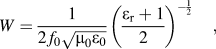
Powder x-ray diffraction (XRD) analysis (Rigaku D/MAX-2500, Tokyo, Japan; scanning from 10 to 90°2θ, with steps of 0.02°) was used to analyze the crystal structure and quantitative determination of sintered samples. As derived in a multicomponent Rietveld analysis of the powder diffraction pattern, with the mass and volume of the unit cell, the weight fraction W of phase p is given by Eq. (1)Reference Hill and Howard12:

where S, Z, M, and V are, respectively, the Rietveld scale factor, the number of formula units per unit cell, the mass of the formula unit, and the unit cell volume.
Microwave dielectric properties of sintered samples were measured by a network analyzer (Agilent 8720ES, Santa Clara, CA) in the frequency range of 8–11 GHz. The dielectric constant was measured by the Hakki-Coleman method, as modified by Courtney,Reference Courtney13 and the unloaded Q values were measured by the cavity method.Reference Kajfez, Chebolu, Abdul-Gaffoor and Kishk14 The temperature coefficient of resonant frequency (τ f) was determined from the resonant frequencies at the temperatures of 25 and 85 °C. The measurement error of dielectric constant, temperature coefficient of resonant frequency, and Qf value were: <0.5% × ε r, 1.5 ppm/°C, and 5% × Qf, respectively.
III. RESULTS AND DISCUSSION
A. Crystal structure and microwave dielectric properties of Zn0.7Mg0.3TiO3
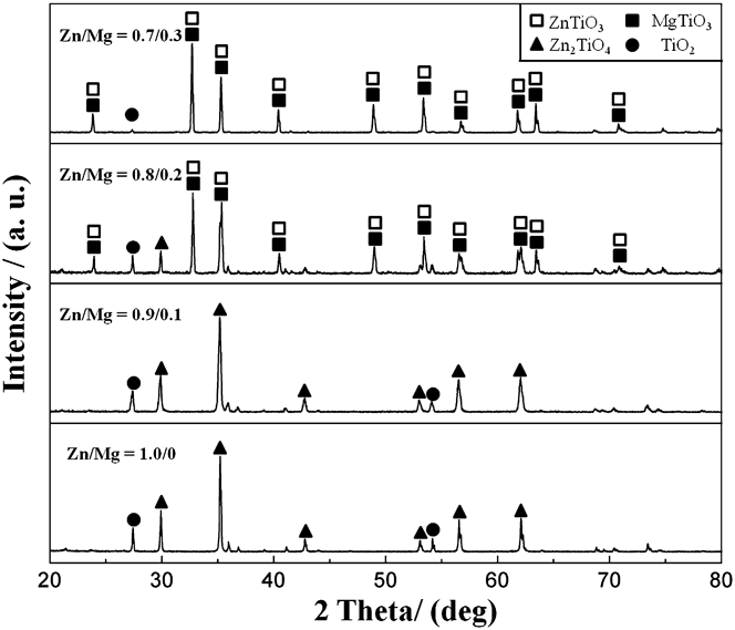
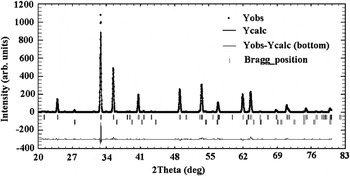
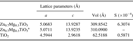
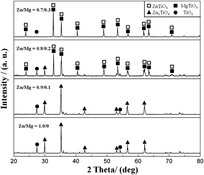
Figure 1 shows the XRD patterns of (Zn1−xMgx)TiO3 microwave dielectric ceramics sintered at 1100 °C for 4 h. To reduce noise, all data had been smoothed by Adaptive smoothing method and had deducted background using Powder X.Reference Dong and Powder15 It was observed that when x = 0 and x = 0.1, the main phases of the system were not ZnTiO3 (JCPDS No. 48-0323) and MgTiO3 (JCPDS No. 48-0323) but were Zn2TiO4 (JCPDS No. 48-0323) and TiO2 (JCPDS No. 48-0323). When x = 0.2, main phases of ZnTiO3 and MgTiO3 and second phases of Zn2TiO4 and TiO2 were identified. When x = 0.3, no Zn2TiO4 were observed, and (Zn0.7Mg0.3)TiO3 with 2.37 wt% of TiO2 was obtained. The weight fraction of TiO2 was calculated directly from scale factors, which were obtained by the quantitative phase analysis using the RietveldReference Rietveld16 refinement. A pseudo-Voight function was used to model the shape of the diffraction peaks. All parameters of interest including background, zero-point, scale factors for all phases, half-width, asymmetry parameters, unit cell parameters, atomic positional coordinates, and temperature factors were refined step-by-step for avoiding correlations. The (Zn0.7Mg0.3)TiO3 (ICSD No. 5529) reported by Liferovich and MitchellReference Liferovich and Mitchell17 and TiO2 (ICSD No. 16636) reported by BaurReference Baur18 were adopted as the starting model. Figure 2 shows the pattern plot after refinement of all parameters of interest. The calculated pattern is overlaid on the measured pattern and the differences between two profiles are plotted along the bottom. The parts of refinement results compared with Ref. Reference Liferovich and Mitchell17 were shown in Table I.
The x-ray diffraction (XRD) patterns of (Zn1−xMgx)TiO3 ceramics sintered at 1100 °C.
The pattern of multiple refinement of Zn0.7Mg0.3TiO3 ceramics.

Crystallographic data obtained from a Rietveld refinement for Zn0.7Mg0.3TiO3 ceramics compared with Ref. Reference Liferovich and Mitchell17.
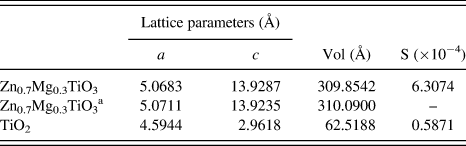
Profile factor (Rp) = 8.33%, Weight profile factor (Rwp) = 13.5%, Goodness of fit indicator (GOF) = 0.8232.
a By Ref. Reference Liferovich and Mitchell17.
Microwave dielectric properties of ε = 24.44, Qf = 15,400 GHz, and τ f = −75 ppm/°C were obtained for Zn0.7Mg0.3TiO3 specimens sintered at 1100 °C for 4 h. Comparing to the previous reports, i.e., Refs. Reference Kim, Byun and Kim7 and Reference Wang, Li, Wu, Ling and Yu19, the ε are slightly smaller and τ f are larger, but the Qf value is obvious higher than those of previous reports. These results are possibly due to the differences of processing, but the basic factor which influences microwave dielectric properties was structural characteristics. To analyze the structural characteristics and the correlations between structures and properties of (Zn0.7Mg0.3)TiO3 in this work, the deviations between theoretical and observed dielectric polarizabilites, the packing fraction, and bond valence were calculated comparing with structure reported in Ref. Reference Liferovich and Mitchell17.
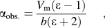
At microwave frequencies, the dielectric constant is not only dependent on the dielectric polarizabilities but also on the structural characteristics such as the distortion, tilting, and/or rattling spaces of oxygen octahedral in unit cell.Reference Shannon and Rossman20–Reference Kim and Choi22 The observed dielectric polarizability (α obs.) was calculated to evaluate the structural dependence of the dielectric constant comparing with the theoretical dielectric polarizability (α theo.). From the Clausius-Mosotti equation, the observed (α obs.) dielectric polarizability was calculated by Eq. (2)Reference Shannon and Rossman23:
and from the additive rule of dielectric polarizability, the theoretical (α theo.) dielectric polarizability was calculated by Eq. (3)Reference Shannon and Rossman23:

where α obs. and α theo. are the observed and the theoretical polarizabilities; α A, α B, and α O are the ionic polarizabilities of A-site ion, B-site ion, and oxygen; ε is the measured dielectric constant; b is 4π/3, and V m is molar volume, respectively. As shown in Table II, the deviation between theoretical and observed dielectric polarizabilites of (Zn0.7Mg0.3)TiO3 in this work was 0.16%.
Comparison of observed and theoretical polarizabilities of Zn0.7Mg0.3TiO3 specimens sintered at 1100 °C.

Based on crystal structural considerations, the packing fraction, defined by the summation of the volume of packed ions over the volume of a primitive unit cell, could be obtained from Eq. (4) for an ilmenite compound:
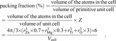
where r Zn, r Mg, r Ti, and r O are the effective ionic radii at each coordination number, V cell is volume of unit cell, and Z = 6 for a ilmenite compound. The packing fraction of (Zn0.7Mg0.3)TiO3 in this work and in Ref. Reference Liferovich and Mitchell17 was shown in Table III. The packing fraction of (Zn0.7Mg0.3)TiO3 in this work was obviously higher than that in Ref. Reference Liferovich and Mitchell17. It indicated that the high Qf value of (Zn0.7Mg0.3)TiO3 in this work is related to the high packing fraction of it. This result, which is high Qf value related to high packing fraction, was in accordance with previous researches.Reference Kim, Chun, Freer and Cernik24, Reference Kim and Jeon25
Packing fraction of Zn0.7Mg0.3TiO3.

a By Ref. Reference Liferovich and Mitchell17.
CN, coordination number.
Another important dielectric property for microwave applications is the temperature coefficient of resonant frequency (τ f), which determines the thermal stability of materials and devices. τ f of materials basically results from the temperature dependence of the dielectric constant (τ ε) related with the chemical nature of constituent ions, the distance between cations and anions, and the structural characteristics originating from the bonding type. These structural characteristics could be evaluated by the bond valence of ions.Reference Kim, Chun and Yoon26–Reference Park, Yoon and Kim28
The bond valence of atom i, V i, was defined as the sum of all the valences from a given atom i, and that was calculated in the Eqs. (5) and (6)Reference Kim, Chun and Yoon26:

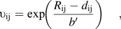
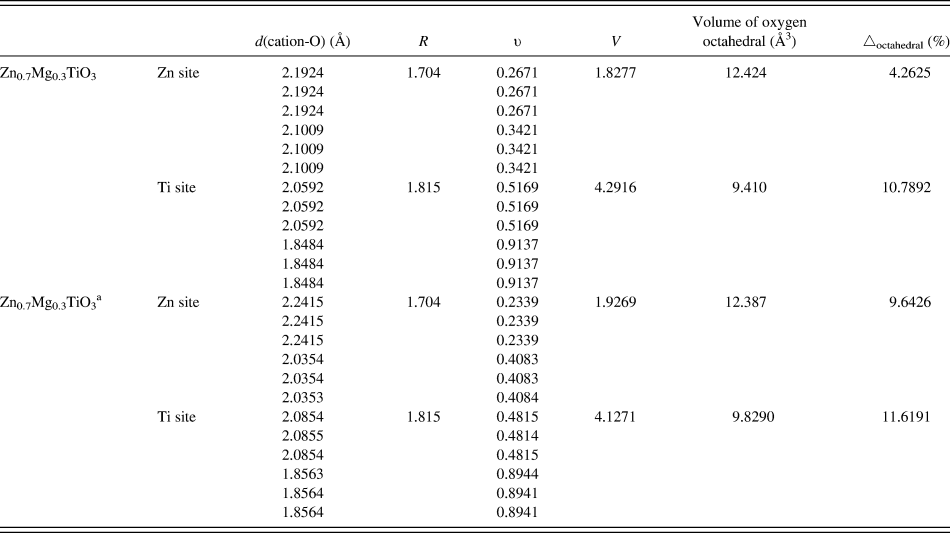
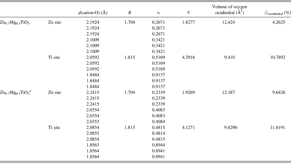
where R ij is the bond valence parameter, d ij is the length of a bond between atom i and j, and b′ is commonly taken to be a universal constant equal to 0.37 Å. The bond valence parameters followed the values in the previous report.Reference Brown and Altermatt29 The bond valence of cations of (Zn0.7Mg0.3)TiO3 ceramics compared with that in Ref. Reference Liferovich and Mitchell17 was shown in Table IV, and it has been reported in Ref. Reference Kim, Chun and Yoon26 that the τ f was strongly dependent on the oxygen octahedral distortion. With increase of oxygen octahedral distortion, the τ f would increase. But in this work, as shown in Table IV, (Zn0.7Mg0.3)TiO3 did not show much large oxygen octahedral distortion. Therefore, the relative large τ f was mainly attributed to the small bond valence on Zn site. Small bond valence on Zn site indicated that the bonding strength between oxygen and Zn2+ ion is weaker. This suggests that the Zn cations of the specimens rattle easily, which means that the contribution of rattling effect to the polarizabilities of the specimens increased, and subsequently the dielectric constant temperature coefficient also gets increased.
Oxygen octahedral distortion and bond valence of cations of Zn0.7Mg0.3TiO3 ceramics in this work compared with Ref. 17.
a By Ref. Reference Liferovich and Mitchell17.
B. Microwave dielectric properties of TiO2 added (Zn0.7Mg0.3)TiO3
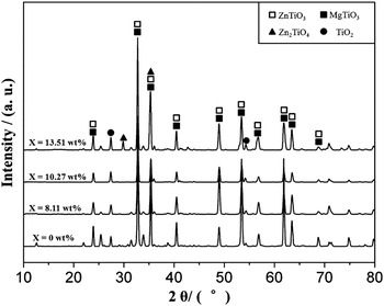
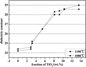
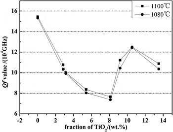
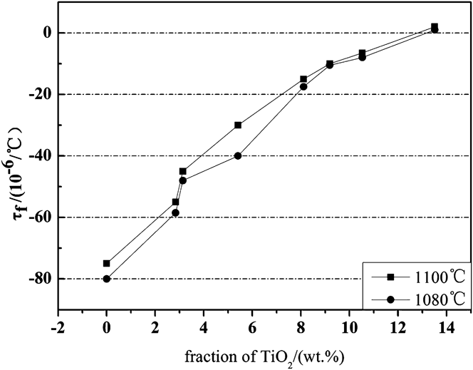
To adjust τ f, (Zn0.7Mg0.3)TiO3 was added with 2.84, 3.14, 5.41, 8.11, 9.19, 10.53, and 13.51 wt%TiO2. Figure 3 shows the XRD patterns of (Zn0.7Mg0.3)TiO3–xTiO2 ceramics. The ε, Qf, and τ f of (Zn0.7Mg0.3)TiO3-xTiO2 ceramics were shown in Fig. 4, Fig. 5, and Fig. 6, respectively.
The XRD patterns of Zn0.7Mg0.3TiO3–xTiO2 ceramics sintered at 1100 °C.

The dielectric constant of (Zn0.7Mg0.3)TiO3–xTiO2 ceramics.

The Qf value of (Zn0.7Mg0.3)TiO3–xTiO2 ceramics.

The τ f of (Zn0.7Mg0.3)TiO3–xTiO2 ceramics.
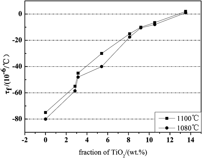
The dielectric constant of the system increased from 24 to 29 and τ f decreased from −80 to 1 ppm/°C along with the increase of TiO2 content. This was in good agreement with Lichnetecker law since TiO2 has a large dielectric constant (100) and positive τ f (+420 ppm/°C).Reference Liou, Shiue and Weng30
The Qf values ranged from 73,000 to 154,500 GHz. As shown in Fig. 5, when TiO2 content was less than 8.11 wt%, the Qf values decreased with the increase of TiO2 content. When the addition of TiO2 was more than 8.11 wt%, the Qf values increased to a maximum and thereafter decreased. The explanations were: the Qf values decreased with the increase of TiO2 content because the Qf values of TiO2 is lower than that of ZnTiO3. Adding more TiO2 could inhibit the decomposition of ZnTiO3 and reduce the amount of Zn2TiO4 due to the following chemical reaction: Zn2TiO4 + TiO2 → 2ZnTiO3. Thus, Qf values increased slightly. However, when the TiO2 content exceeded 10.53 wt%, there existed unreacted TiO2 with a low Qf values. As a result, the Qf values of system decreased again.
The 0.82(Zn0.7Mg0.3)TiO3–0.18TiO2 microwave dielectric ceramics, which satisfied the requirement as a substrate material for microstrip patch antenna, showed a microwave dielectric properties as: ε = 28.5, Qf = 125,050 GHz, and τ f = −6.5 ppm/°C.
C. Fabrication of dielectric microstrip antenna
To prove the advantages of 0.82(Zn0.7Mg0.3)TiO3–0.18TiO2 (ε r = 28.5) microwave dielectric ceramics to be used as a substrate material for microstrip patch antenna, a rectangular microstrip antenna was designed and fabricated compared with FR4 (ε r = 4.4).
D. Analysis of rectangular microstrip antenna
According to the analytic method of transmission line model, the antenna’s parameters can be calculated with the formula:
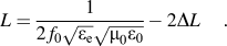
If W/h ≥1, then

or


in which, f 0 is the central frequency of the antenna, ε 0 is the permittivity of vacuum, μ 0 is the permeability of vacuum, ε r is the relative permittivity of the substrate, ΔL is the equivalent radiation slot width, ε e is the effective dielectric constant, and h is the thickness of the dielectric between the conducting ground plane and the microstrip.
E. Simulation on Ansoft HFSS
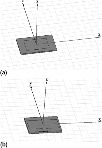
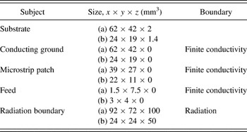
High frequency structure simulator (HFSS) is a design tool utilizing finite element method (FEM) to solve electromagnetic problems in which the simulation of antenna is a common application. Since the design formula above is empirical, and the simulation result is based on actual situation, there exists difference between the simulation result and the theory. This kind of deviation may be improved through the antenna simulation model adjustment. Figure 7 shows the antenna simulation model with respect to different dielectric substrates in HFSS. Main parameters are shown in Table V.
The antenna simulation model using substrates (a) FR4 and (b) proposed dielectric.

Parameters of the simulation model using substrates: (a) FR4 and (b) proposed dielectric 0.82(Zn0.7Mg0.3)TiO3–0.18TiO2.

F. Result of the antenna simulation
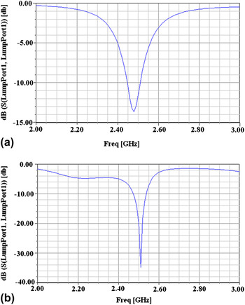
(i) Figure 8 demonstrates that the central frequency of the two antenna using different substrates are both around 2.5 GHz, and the return loss at central frequency are −13.84 and −34.96 dB.
FIG. 8.Input reflection coefficients of the microstrip antenna using substrates (a) FR4 and (b) proposed dielectric.

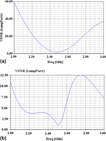
(ii) Figure 9 illustrates that voltage standing wave ratio (VSWR) are 1.28 and 1.05, respectively, which satisfies the requests in the antenna system that the ratio is smaller than 1.5. The VSWR is the ratio of maximum to minimum voltage in a standing wave pattern. It is a measure of impedance mismatch between the transmission line and its load. The higher the VSWR, the greater the mismatch.
FIG. 9.Voltage standing wave ratio (VSWR) of the microstrip antenna using substrates (a) FR4 and (b) proposed dielectric.
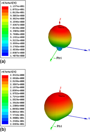
(iii) Figure 10 shows that the antennas are both very directive in the direction of z-axis (red color means strong radiation intensity).
FIG. 10.Antenna pattern of the microstrip antenna using substrates (a) FR4 and (b) proposed dielectric.


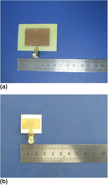
Figure 11 shows the real photos of the microstrip antennas using FR4 and the proposed dielectric as substrate materials, respectively. In comparison with FR4, the antenna using the proposed dielectric not only shows a tremendous reduction in the insertion loss but also demonstrates a considerable reduction in size.
Real photos of the microstrip antenna using substrates (a) FR4 and (b) proposed dielectric.

IV. CONCLUSIONS
0.82(Zn0.7Mg0.3)TiO3–0.18TiO2 using as a substrate material for microstrip patch antenna was investigated. On inhibiting the decomposition of ZnTiO3 by adding sufficient amount of MgO, high quality factor microwave dielectric material (Zn0.7Mg0.3)TiO3 was obtained firstly. The high Qf value of Zn0.7Mg0.3TiO3 in this work is related to the high packing fraction of it, and the relative large τ f was mainly attributed to the small bond valence on Zn site. To adjust τ f, TiO2 was added to (Zn0.7Mg0.3)TiO3 and 0.82(Zn0.7Mg0.3)TiO3–0.18TiO2 with an ε r of 28.5, a Qf of 125,050 GHz, and a near-zero τ f which satisfied the requirement as a substrate material for microstrip patch antenna was obtained at 1100 °C.
The study of 0.82(Zn0.7Mg0.3)TiO3–0.18TiO2 showed that it was promising for applications in microwave devices (antennas for instance), where the miniaturization, high radiation efficiency, and temperature stability of the devices were crucial. A dielectric microstrip antenna was successfully designed using 0.82(Zn0.7Mg0.3)TiO3–0.18TiO2 ceramics as substrate. The return loss was −34.96 dB at 2.5 GHz, and the temperature variation of the resonance frequency was low.
ACKNOWLEDGMENTS
This work was supported by 863 program (2007AA03Z423).