NOMENCLATURE
- A
-
test section cross-sectional area (m2)
- M
-
Mach number
- p 0
-
absolute stagnation pressure (bar)
- Re
-
Reynolds number
Abbreviations
- ADD
-
Agency for Defense Development (South Korea)
- AEDC
-
Arnold Engineering Development Complex (US)
- AETC
-
NASA Aerosciences Evaluation and Test Capabilities (US)
- AGARD
-
Advisory Group for Aeronautical Research and Development (NATO)
- AIAA
-
American Institute of Aeronautics and Astronautics
- ARA
-
Aircraft Research Association (UK)
- ARC
-
Aeronautical Research Council (UK)
- ASE
-
Aero Systems Engineering (US)
- ASRD
-
Aeronautical Systems Research Division (Taiwan)
- ATI
-
Aerospace Technology Institute (UK)
- ATLA
-
Acquisition, Technology & Logistics Agency (Japan)
- ATP
-
Aeronautics Test Programme (US)
- AVIC
-
Aviation Industry Corporation of China
- BTWT
-
Boeing Transonic Wind Tunnel (US)
- CAAA
-
China Academy of Aerospace Aerodynamics
- CARDC
-
China Aerodynamics Research and Development Centre
- CFD
-
Computational Fluid Dynamics
- CSIR
-
Council for Scientific and Industrial Research (South Africa)
- CSIR-NAL
-
National Aerospace Laboratories (India)
- CTS
-
Captive Trajectory System
- DLR
-
Deutsches Zentrum für Luft- und Raumfahrt (Germany)
- DNW
-
German-Dutch Wind Tunnels (DLR & NLR)
- DPSP
-
Dynamic Pressure Sensitive Paint
- DSO
-
Defense Science Organization (Singapore)
- EFD
-
Experimental Fluid Dynamics
- EPSRC
-
Engineering and Physical Sciences Research Council (UK)
- ETW
-
European Transonic Wind Tunnel
- EU
-
European Union
- FFA
-
Aeronautical Research Institute (Sweden)
- FOD
-
Foreign Object Damage
- HST, HWST
-
High-Speed Wind Tunnel
- IAI
-
Israel Aerospace Industries
- INCAS
-
National Institute of Aerospace Research (Romania)
- ISRO
-
Indian Space Research Organisation
- JAXA
-
Japan Aerospace Exploration Agency
- LDA
-
Laser Doppler Anemometry
- MSWT
-
Medium-Speed Wind Tunnel
- NAE
-
National Aeronautical Establishment (Canada)
- NAL
-
National Aerospace Laboratories (India)
- NASA
-
National Aeronautics and Space Administration (US)
- NATA
-
National Aeronautical Test Alliance (US)
- NLR
-
Royal Netherlands Aerospace Centre
- NPAT
-
National Partnership for Aeronautical Testing (US)
- NPL
-
National Physical Laboratory (UK)
- NRC
-
National Research Council (Canada)
- NTF
-
National Transonic Facility (NASA Langley, US)
- NWTA
-
National Wind Tunnel Alliance (US)
- NWTC
-
National Wind Tunnel Complex (US)
- NWTF
-
National Wind Tunnel Facility (UK)
- ONERA
-
Office National d’Etudes et de Recherches Aérospatiales (France)
- PES
-
Plenum Exhaust System
- PIV
-
Particle Image Velocimetry
- PSP
-
Pressure Sensitive Paint
- PSWT
-
Polysonic Wind Tunnel
- S&C
-
Stability and Control
- SoW
-
Statement of Work
- STARCS
-
Sjöland and Thyselius Aerodynamics Research Centre (Sweden)
- STAI
-
Supersonic Tunnel Association International
- TsAGI
-
Central Aero-Hydrodynamic Institute (Russia)
- TDT
-
Transonic Dynamics Tunnel (NASA Langley, US)
- TPT
-
Transonic Pressure Tunnel (NASA Langley, US)
- TWT
-
Transonic Wind Tunnel
- UAV
-
Unmanned Air Vehicle
- UOH
-
User Occupancy Hour
- UPWT
-
Unitary Plan Wind Tunnel (NASA Ames and NASA Langley, US)
- VTI
-
Military Technical Institute Belgrade (Serbia)
1.0 Introduction
Despite more than 40 years of predictions of their imminent demise [Reference Kraft1], wind tunnels remain an essential element in the design and development of flight vehicles. However, graduates in aerospace engineering tend to have had relatively little exposure to the demands of industrial experimental work in large-scale facilities, particularly at high speed. As a broad generalisation, aerospace universities are well provided with low-speed wind tunnels of a reasonable size, available for both teaching and research. In contrast, high-speed facilities are rather rarer and tend to be relatively small and focused on research. For example, in the UK there are around 45 institutions offering undergraduate degrees in Aerospace or Aeronautical Engineering. Almost every one of these has a low-speed wind tunnel, but only seven have an operational transonic test facility.
The situation is exacerbated by a lack of up-to-date reference material: the most recent textbooks on high-speed wind tunnels were published in the 1960s [Reference Goethert2–Reference Pope and Goin5], supplemented by two conference papers reviewing the state-of-the-art, Ref. [Reference Ring and Milillo6] in 1970 and Ref. [Reference Blackwell7] in 1981. Most subsequent aerodynamics textbooks (with the recent exceptions of Refs Reference Rathakrishnan8 and Reference Chanetz9) are either rather superficial in their coverage of high-speed testing, or draw heavily on Ref. [Reference Pope and Goin5]. The proceedings of the Supersonic Tunnel Association InternationalFootnote 1 (STAI) are a mine of information, but are unfortunately available to member organisations only.
This paper aims to partially fill this gap by providing an up-to-date and reasonably comprehensive overview of the current and near-term status of large-scale high-speed industrial wind tunnels and wind tunnel testing. The review is largely aimed at new/recent entrants to the field, with the goal of helping them make the daunting step from research projects and lab work in small-scale university facilities to testing commercial projects in large-scale industrial facilities. Section 2 reviews the current global status of high-speed wind tunnels, focusing on tunnels with a transonic test capability. Typical configurations for large transonic tunnels are presented in Section 3. Finally, Section 4 presents some aspects of industrial-scale testing, including typical challenges faced in production testing. All these sections focus on features that are likely to be less familiar to the new graduate or non-specialist.
2.0 Status of industrial high-speed facilities
2.1 Scope and definitions
Attention will be focused on wind tunnels capable of high-subsonic/transonic/low-supersonic testing (typically, a Mach number range of 0.7–1.3), since this flow regime presents the most challenges for wind-tunnel testing in general, and is likely to be the least familiar to new entrants. More broadly, industrial supersonic and hypersonic tunnels do not differ significantly in their fundamental operation from typical university facilities, whilst issues associated with commercial testing and large size are common across the spectrum of industrial facilities. Cryogenic or heavy gas operation will not be considered here, since these would require a review article each to address properly (e.g. Refs Reference Goodyer10, Reference Ivanco11).
Transonic test capability implies a ventilated (porous, slotted, or open) test section, and hence purely supersonic wind tunnels with solid wall test sections are also excluded from this review. Wind tunnels with transonic test capability are typically referred to as transonic (mostly closed-return continuous tunnels with a maximum Mach number ≤ 2) or trisonic (mostly open-return intermittent tunnels with a maximum Mach number ≥ 3).
For brevity, the term transonic in this paper will normally cover both classes of tunnel, except where stated otherwise. For trisonic tunnels, the focus will be on their use for transonic testing, rather than for supersonic testing.
2.2 Transonic wind tunnels of the world
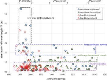
Figure 1 presents a picture of the history of transonic wind tunnels around the world, plotting test section size against year of entry into service. Here, test section size is characterised by the standard reference length
 $\sqrt{A}$
, where A is the cross-sectional area of the test section. For the purposes of this review, size is a more useful measure than (for example) the test envelope, because it is primarily the physical size of a wind tunnel, and the operational complexity of the associated plant, that distinguish an industrial facility from a research facility.
Transonic wind tunnels of the world.

Filled symbols denote tunnels that are still operational, and open (red) symbols tunnels that have since closed. Circles indicate continuous running, and upright triangles intermittent running facilities.
Looking first at size and type, four reasonably distinct classes of transonic wind tunnel can be discerned in Fig. 1:
-
1. Research facilities (
 $\sqrt{A}$
∼ 0.1–1.0 m) - smaller continuous and intermittent tunnels operated by universities, and by national research organisationsFootnote
2
. These facilities are the most vulnerable to closure, although new ones continue to be built.
-
2. Mid-range intermittent tunnels (
$\sqrt{A}$
∼ 1.2–1.5 m, or 4-5 ft) – transonic and trisonic tunnels operated by national research organisations, and by aircraft manufacturers. Numbers in operation have continued to increase steadily since the 1960s, with only one having ever closed completelyFootnote
3
. -
3. Large continuous tunnels (
$\sqrt{A}$
∼ 1.8–2.8 m, or 6-10 ft) – transonic tunnels operated by national research organisations, and by independent commercial organisations. Several of these tunnels were closed in the 1990s, but since then numbers have remained relatively stable. -
4. Very large continuous tunnels (
$\sqrt{A}$
> 3 m, or > 10 ft) – a handful of older transonic tunnels operated by national research organisations.


For the purposes of the rest of this review, classes (2), (3) and (4) will be grouped together as industrial facilities, characterised by a test section reference length
 $\sqrt{A}$
≥ 1.2 mFootnote
4
. This is a more useful criteria than (for example) the test envelope, because it is primarily the physical size and operational complexity of the associated plant that distinguishes an industrial facility from a research facility.
Now looking at the time axis on Fig. 1, there have been broadly speaking three generations of industrial tunnel construction:
-
1950s: a 1st generation of large continuous transonic wind tunnels started to appear in the late 1940s, the earliest based on modified wartime high-subsonic tunnels. Later in the decade, aircraft manufacturers as well as national research establishments began to build mid-range trisonic intermittent tunnels, mostly blowdown facilities.
-
1980s: a small number of more capable large transonic and cryogenic tunnels appeared in the 1980s and early 1990s. Two large intermittent tunnels also came online in this period, whilst mid-range trisonic tunnels continued to be built.
-
1990s: an intervening period of retrenchment, with several 1st generation facilities closed or mothballed. This decade also saw a number of ambitious projects for new tunnels cancelled, most notably the National Wind Tunnel Complex project in the United States [Reference Sawyer and Krynytzky12].
-
2010s: The last ten years have seen a resurgence of transonic wind tunnel R&D and construction activity. In addition, several mothballed supersonic facilities have been reactivatedFootnote 5 .
2.3 Industrial transonic wind tunnel population
Received wisdom is that wind tunnels are in decline, a thing of the past, but a simple head count demonstrates that the opposite has in fact been the case in recent years for high-speed industrial tunnels.
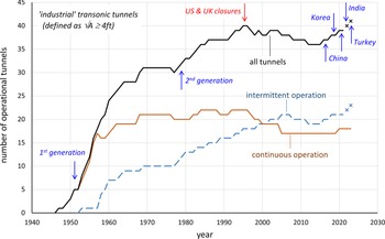
Figure 2 shows the variation with time of the world population of operational industrial-scale wind tunnelsFootnote 6 . The 1950s saw a rapid build-up in the number of larger continuous facilities, which then remained relatively constant until the UK and US started closing tunnels in the 1990s. The smaller intermittent facilities got off to a delayed start in the mid-1950s, with a later surge as 2nd generation tunnels began to appear in the 1980s.
Operational industrial transonic wind tunnel population by year.

In the last decade, numbers of operational tunnels have begun to increase again, with new-builds FL-60 and FL-62 in China, and the relocation and reactivation of the ex-FFA T1500 in Korea. A new 1.2 m trisonic blowdown tunnel is currently under construction for ISRO in IndiaFootnote 7 , with another in the planning stage in Turkey.
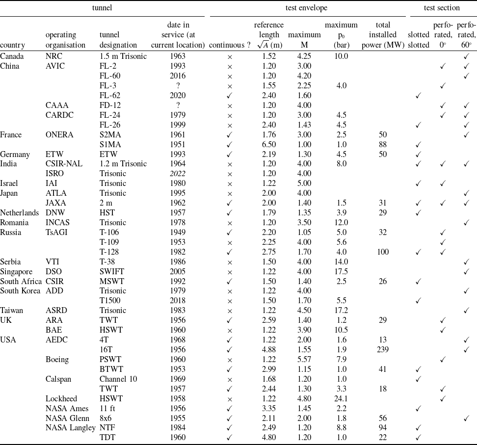
As of 2021, there are 39Footnote 8 industrial transonic wind tunnels operational around the world, of which 18 are continuous running tunnels and 21 are intermittent running tunnels, supplemented by a fluctuating population of around 60–70 smaller research facilities. Taking into account ongoing projects, the world population of industrial transonic tunnels is likely to exceed its 1995 peak by the middle of this decade.
Current operational and near-operational transonic and trisonic tunnels are listed alphabetically by country in Table 1 Footnote 9 . The United States remains the major operator with 11 tunnels, but the newest of these (NTF at NASA Langley) was commissioned 35 years ago, in 1984. China’s intensive tunnel building programme has seen it move past Russia into second place with 7 tunnels, 4 of which were commissioned in the 21st century. Almost all of these countries have a national aerospace research organisation which either operates or provides indirect support to their transonic facilities; the exceptions are the UK and Israel.
Operational and near-operational industrial transonic wind tunnels

2.4 Transonic wind tunnels in the UK
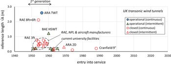
Having considered global trends in transonic wind tunnel numbers and capabilities, it is instructive to look briefly at the situation in the UK. Figure 3 shows the UK facilities from Fig. 1, plotted at the same scale to permit a direct comparison. Data on UK high-speed facilities has been collated from a number of sources, including Refs Reference Goethert2 (1961), Reference Irwin13 (1965), 14 (1977), and Reference Prince15 (2015).
Almost all the important UK transonic facilities (the exception being the 2D tunnel at ARA) came into service in the 1950s. These can be split into three groups:
-
(a) Modifications of existing continuous tunnels – the supersonic 3 ftFootnote 10 at RAE Bedford acquired a slotted wall transonic test section in 1953 [Reference Sutton16], and the wartime high-subsonic 10 ft × 7 ft at RAE Farnborough was rebuilt as the transonic 8 ft × 6 ft in 1954.
-
(b) New research tunnels – a number of smaller slotted wall tunnels at the NPL, and at several aircraft manufacturersFootnote 11 .
-
(c) New industrial tunnels – the ARA 9 ft × 8 ft TWT transonic continuous tunnel at Bedford (1956 [17]), and the English Electric (now BAE) 4 ft HSWT trisonic intermittent tunnel at Warton (1960 [18]).
UK transonic wind tunnels (scale as Fig. 1).

However, the closures of the RAE tunnel sites at Farnborough and Bedford, and the NPL high-speed tunnels at Teddington, combined with the gradual amalgamation and rationalisation of UK aircraft company facilities, have resulted in the loss of almost all of these early wind tunnels.
There now remain only two operational industrial-scale transonicFootnote 12 wind tunnels in the country: the ARA TWT and the BAE HSWT. These are early 1st generation facilities, which retain their original 1950s test section configurations (i.e. high-porosity perforated walls with normal holes).
These facilities are supported by a handful of small (
 $\sqrt{A}$
< 0.25 m) research tunnels [Reference Prince15], five in universitiesFootnote
13
and one at ARA. These are all intermittent facilities, and even the newest has been in service for over 55 years. Two of the university facilities are part of the National Wind Tunnel Facility [Reference Morrison and Gouder19] consortium, although EPSRC and ATI funding for this group formally ended in 2019. The last purpose-built 2D transonic tunnel in the UK (1969 [Reference Humphreys20]) ceased operationsFootnote
14
at ARA in the mid-2000 s. The last new university transonic tunnel, the continuous 9 in × 7.5 in at Cranfield University (1988 [Reference Gibb21]), only ran for a few years into the 1990s before being closed due to a drive failure. There are no larger (
 $\sqrt{A}$
∼ 0.3–1.0 m) transonic (or indeed supersonicFootnote
15
) research facilities left operational in the UK. Further, with the break-up of DERA in 2001, the UK lost the background fundamental research ecosystem that had long supported its industrial facilities.
2.5 The continuing need for high-speed wind tunnels
2.5.1 Wind tunnel usage
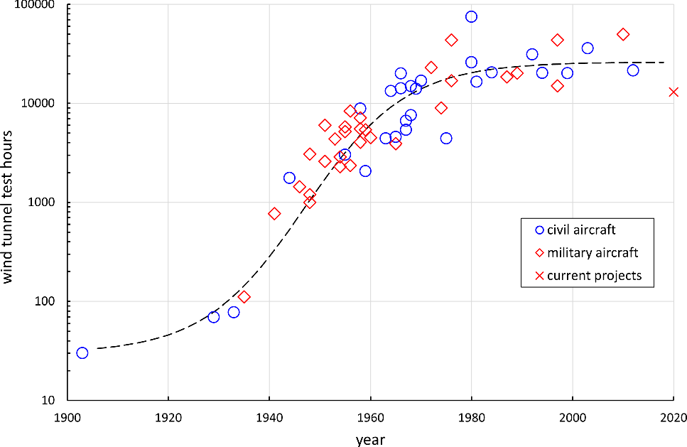
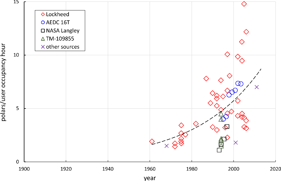
The number of wind tunnel test hours required for a major aircraft programme has remained relatively stable for several decades. This is illustrated by Fig. 4, which is based on a plot from a 1994 NASA facilities study [22], supplemented with more recent data from a wide variety of sources [Reference Parsons23–Reference Mitchell30]. After a rapid increase post-WW2, wind tunnel test hours per programme have levelled off at around 20,000 hours, with both civil and military programmes showing similar trends. This levelling-off has been accompanied by a very significant general improvement in wind tunnel data productivityFootnote 16 (Fig. 5 [22,Reference Kraft and Huber24]), which appears to have compensated to some extent for the ever-increasing complexity of high-speed flight vehicles.
Wind tunnel test hours per programme.

High-speed wind tunnel data productivity.

To put these numbers in context, high-intensity operations in a well-maintained, fully crewed industrial wind tunnel could generate around 1,500–2,000 hours of testing per year; however, most facilities do not achieve anywhere near this level of utilisation. At a national level, Ref. [Reference Kraft and Huber24] reported that the US high-speed wind tunnel test capacity in 2009 was about 6,000 hours per year.
Figure 4 indicates that required wind tunnel capacity at any time is proportional to the number of active flight vehicle programmes. Unfortunately, this is not a straightforward metric to quantify, since the customer base for transonic wind tunnels includes civil and military aircraft, missiles, and spacecraft, with test programmes covering new designs, developments of existing designs and operational support (e.g. weapons clearance). A 2010 review of future wind tunnel test requirements [Reference Melanson, Chang and Baker31] suggested that at that time numbers of aircraft designs (civil, military, UAV) reaching first flight per decade had not changed significantly since the 1980s. More recently, there has been a significant revival in military aircraft and spacecraft test activity; anecdotally, many industrial test facilities are close to capacity, with some having to turn work away.
Computational fluid dynamics (CFD) has not made any noticeable impact on wind tunnel usage for flight vehicle development programmes [Reference Kraft1]. If anything, Figs 4 and 5 together suggest that underlying data requirements (i.e. polars per programme) have been steadily increasing over the past 40 years. The computer has very clearly not replaced the high-speed wind tunnel in any form whatsoever, whilst the widely touted integrated use of computational and experimental fluid dynamics (EFD) [Reference Kraft32–Reference Dunn34] has in practice simply been a continuation of the complementary use of theoretical, numerical, and experimental methods that has always been routine in industrial testing.
2.5.2 Some recent investments
A further pragmatic indicator of the continuing need for large high-speed wind tunnels is the amount of time and money governments and operators are prepared to spend on them. In recent years this investment has broadly split into three categories:
-
1. Building new facilities, or reactivating mothballed facilities.
-
Looking at the past 20 years or soFootnote 17 , at least six new industrial-scale high-speed wind tunnels have been built in China: FL-26 (1999) and FL-28 (2010) at CARDC, FL-3 (∼2000), FL-60 (2016), and FL-62 (2020) at AVIC, FD-12 (∼2000) at CAAA, plus several smaller research-scale facilities. Recent publications indicate that this impressive tunnel building programme is supported by intensive R&D activity on advanced instrumentation and test techniques. India has a new 1.2 m trisonic intermittent tunnel nearing completion at ISRO, and has plans for a 2.5 m trisonic continuous tunnel at CSIR-NAL. Turkey also has ongoing projects for new continuous and intermittent high-speed tunnels, although it is not clear how much progress has been made to date.
-
Four large transonic/supersonic wind tunnels have been reactivated over the same period: the Unitary Plan tunnels at NASA Langley (4 ft supersonic continuous, 2017) and NASA Ames (11 ft transonic continuous, 2000), 16S at AEDC (16 ft supersonic continuous, 2019), and DNW’s SST (1.2 m supersonic intermittent, 2018). Two other tunnels have been relocated and reactivated – SWIFT from Lockheed to DSO in Singapore (4 ft trisonic intermittent, 2005), and T1500 from FFA via STARCS to ADD in South Korea (1.5 m transonic intermittent, 2019).
-
-
2. Increasing top-level organisational support for existing facilities.
-
Two US programmes are of particular relevance to industrial wind-tunnel testing: AEDC’s ten-year programme to “reinvigorate technical rigour” [Reference Best, Kraft and Huber35–Reference West37], and NASA’s very recent move to fully funding critical ground test facilities [Reference Colantonio38].
-
Ref. [Reference West37] summarises with commendable honesty actions taken at AEDC since 2009 to recapture its heritage of technical excellence, and is recommended as essential reading to anyone concerned with the management of large wind tunnel facilities. Following a recognition in the mid-2000s that a “myopic focus on cost” had compromised overall test effectiveness, plans to invest in workforce development and facility enhancements [Reference Best, Kraft and Huber35,Reference Huber, Kraft and Best36] finally got underway in 2015. These involved the US government taking back responsibility for leading test execution, with AEDC reorganised into a “mission-centric combined test force” structure, and a major restructuring of the test support contracts.
-
After the lean years of the 1990s, the last 20 years have seen a gradual turn-around in the fortunes of large wind tunnels in the United States, with a succession of national initiatives summarised in Ref. [Reference Bell39], from the National Wind Tunnel Alliance (NWTA) in 1998 to the National Aeronautical Test Alliance (NATA) in 2000 to the National Partnership for Aeronautical Testing (NPAT) in 2007. Within NASA, the Aeronautics Test Programme (ATP) was established in 2006 to retain and invest in NASA aeronautics test capabilities [Reference Marshall40], which by 2015 had become the Aerosciences Evaluation and Test Capabilities (AETC) Project [Reference Proffitt41], now referred to as the AETC PortfolioFootnote 18 [Reference Bell39].
-
One significant, but not widely reported, outcome of these years of reorganisations and reviews was a major change in 2017 to NASA’s funding model for its AETC facilities [Reference Colantonio38]. Previously, the AETC funding allocation covered only 50% of fixed costs, with the remainder of fixed and variable costs covered by customer revenue. From 2017, 100% of fixed costs were covered for NASA customers, with consumables (including power) added in 2019. This new funding model also provides for investment in workforce and assets, covering operations, maintenance, capability advancement, and test technology.
-
In the UK, top-level support for industrial-scale transonic and supersonic facilities has been fragmented and inconsistent; as a consequence it has been much less effective in maintaining and enhancing a national capability (see Fig. 3).
-
-
3. Major upgrades or refurbishments of existing facilities.
-
Many industrial high-speed wind tunnels have seen significant recent investment in the basic plant and instrumentation. These include:
-
− test section upgrades for the BAE HSWT, JAXA 2 m, and CAAA FD-12 tunnels.
-
− nozzle upgrades for the BAE HSWT, SWIFT, AEDC 4T, TsAGI T-109, VTI T-38, ADD Trisonic, and NRC 1.5 m tunnels.
-
− compressor upgrades for the IAI Trisonic, ARA TWT, and Lockheed HSWT tunnels.
-
− the STARBUKS upgrade project for the NASA Langley NTF [Reference Paryz42].
-
-
A wide range of enhancement work is also currently taking place in NASA facilities, made possible by the new funding model discussed above.
-
On the commercial side, in January 2020 Calspan in the United States announced a $6M investment programme for their transonic wind tunnel division. The company has also recently acquired a balance manufacture and calibration capability (Triumph Aerospace Systems, 2016), and hypersonic and propulsion test facilities (Aero Systems Engineering, 2020 and ACEnT Laboratories, 2021).
-
In the UK, the two remaining industrial facilities have had significant investment in the last 10 years: the BAE HSWT has had the flexible nozzle, test section, and model support system refurbished, whilst the ARA TWT has received over £15M from the UK government, primarily to support specific test capability development projects (albeit with widely varying degrees of success).
3.0 Industrial transonic wind tunnels
3.1 Work-Horse industrial facilities
Having defined an industrial tunnel in Section 2.2 as one having a test section reference length
 $\sqrt{A}$
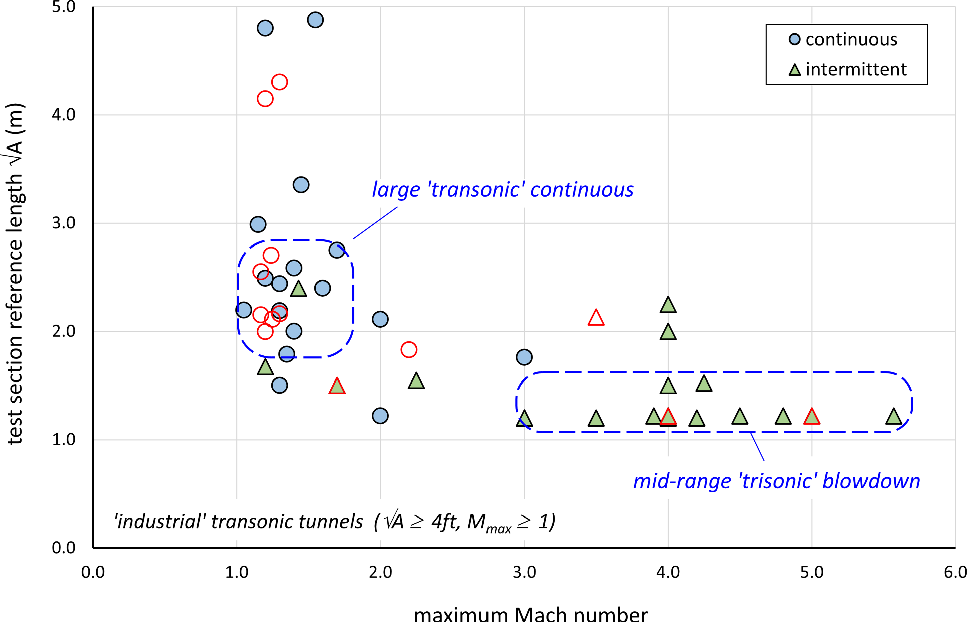
≥ 1.2 m, Fig. 6 shows the relationship between maximum Mach number and size for these facilities. Taken together with Fig. 1, this plot indicates that most industrial transonic tunnels (including almost all built since the mid-70s) fall into one of two categories:
-
1. Large continuous transonic tunnels → maximum M ∼ 1.1–1.7,
$\sqrt{A}$
∼ 1.8–2.8 m. -
2. Mid-range blowdown trisonic tunnels → maximum M ∼ 3–5,
$\sqrt{A}$
∼ 1.2–1.5 m,


Size and maximum mach number for industrial transonic wind tunnels.

These work-horse wind tunnels are used for the vast majority of civil and military flight vehicle testing; together they present almost all the significant design featuresFootnote 19 , test types, and operational issues likely to be encountered in high-speed industrial testing.
3.2 Typical facility layouts
3.2.1 Continuous transonic tunnels
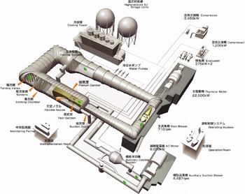
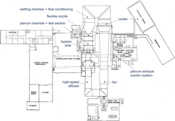
Figures 7 and 8 illustrate the layout and circuit elements of two typical work-horse transonic continuous tunnels. Most of the elements of these tunnels are common to low-speed tunnels, for which Refs Reference Barlow, Rae and Pope43 and Reference Bradshaw and Pankhurst44 remain standard sources. However, there are a number of features of industrial transonic facilities which may be less familiar to the non-specialist, including the pressurisation, drying and cooling systems, and the ventilated test section. These are discussed in more depth in Refs Reference Goethert2, Reference Pope and Goin5 and Reference Chanetz9.
A typical transonic continuous tunnel (JAXA 2 m [Reference Ueno, Kohzai and Koga49]).

Transonic continuous tunnel components (ARA TWT [Reference Gatliff and Gunnel50,51]).

Transonic continuous tunnels can be sub-categorised further on the basis of their pressurisation capabilities:
-
(a) unpressurised atmospheric facilities (p 0 ∼ 1 bar),
-
(b) pressurised low-pressure facilities (maximum p 0 ∼ 1.2–2 bar), and
-
(c) pressurised high-pressure facilities (maximum p 0 ∼ 2–9 bar).
High-pressure tunnels can be pumped up to get closer to full-scale Reynolds numbers. Low-pressure tunnels cannot generally match full-scale Re (except perhaps for some missile tests), but have a wide enough pressure range to be able to maintain a constant Re as Mach number is varied.
3.2.2 Trisonic blowdown tunnels
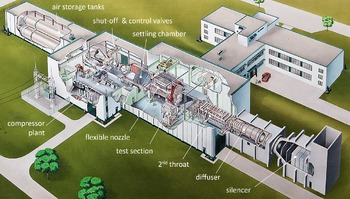
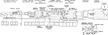
The majority of industrial intermittent facilities are open-circuit blowdown tunnels venting to atmosphere, Figs 9 and 10. The basic configuration of these facilities has changed relatively little since they first appeared in the 1950s [Reference Ferri and Bogdonoff45]. Run times depend on Mach number and total pressure, but are typically less than a minute for transonic testing, with recharge times of the order of 30 minutes [46,Reference Brown47]. A number of these blowdown facilities have been retrofitted with an ejector system in the diffuser to reduce model loads and extend the test envelope [Reference Benne48].
A typical trisonic blowdown tunnel (NRC 1.5 m [Reference Brown47]).

Trisonic blowdown tunnel components (NRC 1.5 m [Reference Brown47]).

3.3 Transonic test sections
For transonic testing all industrial facilities use a ventilated test section, with perforated or slotted walls backed by a plenum chamber. Wall ventilation has five interrelated functions [Reference Goethert2,Reference Pope and Goin5], all of which are important for industrial testing:
-
1. to prevent choking in the test section at transonic conditions,
-
2. to set or adjust freestream Mach number at low-supersonic conditions,
-
3. to compensate for boundary layer growth in the test section,
-
4. to reduce or eliminate wall corrections (constraint, blockage, buoyancy) at subsonic conditions [Reference Garner52,Reference Ewald53], and
-
5. to reduce or eliminate interference from wave reflections at supersonic conditions [Reference Davis54,Reference Capone and Coates55].
Functions (1), (2) and (3), and to a certain extent (4), requires a forced outflow from the test section, which can be achieved either passively by venting the plenum directly into the high-speed diffuser, and/or actively by using a Plenum Exhaust System (PES) compressor. For transonic testing, the flow expansion prevents choking at the model; at higher tunnel pressure ratios the flow expansion permits a supersonic flow to be established in the test section without a convergent-divergent nozzle. Many industrial transonic tunnels use this effect to dispense with a nozzle entirely, neatly avoiding the mechanical and aerodynamic design issues associated with low-supersonic nozzles.
For industrial facilities, ventilated wall configurations can be split into four types, all of which can be traced back to the 1st generation of continuous transonic tunnels:
-
(a) longitudinal profiled slots, usually with a fixed sonic nozzle and a passive plenum suction system (e.g. NASA Langley [Reference Becker56–Reference Hansen58]).
-
(b) parallel slots with internal flow baffles, usually with a variable-geometry convergent-divergent nozzle and a plenum exhaust system (e.g. NASA Ames [Reference Hartman59]).
-
(c) perforated walls with normal holes, usually with a variable-geometry convergent-divergent nozzle and a plenum exhaust system, (e.g. TsAGI [Reference Bedrzhitsky and Roukavets60] and ARA [Reference Haines and Jones61]).
-
(d) perforated walls with holes inclined at 60° to the freestream (e.g. AEDC [Reference Goethert2,Reference Pindzola and Chew62]).
The optimum wall porosity level and longitudinal distribution is different for each of the ventilation functions and ventilation types listed above, and also depend on the model configuration and the test conditionsFootnote 20 . In order to address this issue, a number of transonic tunnels have been built with adaptive or adjustable test-section wall profiles and/or porosity distributions. However, the time taken to re-adjust the wall configuration as Mach number and model incidence change generally results in poor data productivity, so that the very few industrial facilities with an adaptive wall capability now generally leave them fixed in a compromise configuration.
As a very broad generalisation, slotted walls tend to be better suited to transonic testing, and perforated walls better suited to low-supersonic testing, so that (again in general) continuous tunnels tend to have slotted walls and intermittent tunnels tend to have perforated walls. All industrial trisonic tunnels have perforated walls for transonic testing and solid walls for high-supersonic testing, although some also have an alternative slotted wall test section for 2D or semi-span testing. For industrial tunnels with fixed-geometry walls, a compromise porosity level and distribution was almost invariably determined empirically during tunnel commissioning. Typical goals for these wall configuration adjustments include:
-
− minimising the longitudinal variation in centreline Mach number at transonic test conditions [Reference Haines and Jones61,Reference Capone63], hence reducing horizontal buoyancy corrections to cruise drag measurements,
-
− creating a smooth acceleration to low-supersonic flow in the test-section for tunnels without a nozzle [Reference Capone63], and
-
− minimising wave reflection interference for low-supersonic testing [Reference Davis54].
On the last goal, it should be emphasised that in practice wave reflections are never entirely suppressed, particularly in the sonic region. There has been an increasing tendency from customers of industrial facilities to ask for testing in the M = 0.95–1.05 range, but any force or pressure data obtained in this region should be viewed with extreme caution. If obliged to test here, it is essential to have some means of assessing whether wave reflections have impinged on the model. At the very least a geometric assessment of reflection angles should be made, although this is likely to be rather optimistic [Reference Capone and Coates55].
4.0 Industrial testing
4.1 Test planning and management
4.1.1 Guidance on test management
Relatively little has been published on the test process for industrial-scale high-speed testing, and in many cases test engineers are simply expected to learn on the job. The primary formal resource for test planning and management is the AIAA Recommended Practice guide R-092 to best practice for wind tunnel testing. This consists of two volumes, one for managers [64] and one for practitioners [65]. Refs Reference Pope and Goin5 and Reference Barlow, Rae and Pope43 also discuss the test process, but the material is spread across several chapters.
Wind tunnel facility guides and user handbooks also usually include some useful material on test planning and management, but these are often for customers only. Two useful exceptions available on-line are the NASA Ames Test Planning Guide [66], and the AEDC Test Planning Requirements guide [67]. Finally, Ref. [Reference Meija68] provides a rare informal discussion of the practicalities of production wind tunnel testing in aerospace, from a Boeing perspective.
4.1.2 The test process
The documents listed above present a neat and linear picture of the wind tunnel test process, divided into six reasonably well-defined and (ideally) sequential activities:
-
(a) test objectives and requirements – setting test objectives and technical requirements needed to meet the top-level programme goals.
-
(b) test planning – development and management of a detailed test project plan.
-
(c) model design and manufacture – development and fabrication of new models, or modification and refurbishment of existing models.
-
(d) pre-test preparation – final on-site preparation of the test plan, model, instrumentation, and facility.
-
(e) test phase – model installation, testing, and removal.
-
(f) post-test activities – disposal or storage of test hardware, data review and delivery, and project documentation.
In practice, the test process in an industrial wind tunnel is never so straightforward, as discussed in Section 4.3.
4.1.3 Test aims
A wind tunnel test is a means to an end, and so it is essential to have a clear statement of the problem being addressed and the purpose of the test, that all of the participants are aware of; Ref. [Reference Barlow, Rae and Pope43] notes that this seemingly obvious point is often overlooked, whilst AIAA-R-092 is rather ambiguous on definitions and hierarchy of test aims.
The aims of a test can be categorised as:
-
(a) programme goals – why is the test being conducted?
-
(b) test objectives – what needs to be measured?
-
(c) test requirements – how is the data to be obtained?
Goals should be broad, long-term, and reference the business benefit. For an industrial wind tunnel test, the goals should for example define: what are the questions the data is needed to answer, who are the customers for the data, when do they need it by, and how much can they afford? The critical goal is the first; this largely determines the scope of the test, the test objectives, the test priorities, and the test success criteria. Unfortunately, it is probably the goal that causes the most problems, particularly when facility and/or customer test team members are not fully briefed on it.
Objectives are the strategies needed to achieve a goal. Wind tunnel test objectives could include the test concept, the model configuration, the test envelope, the quantities to be measured, and the test success criteria. In principle, the test objectives depend only on the test goals; in practice, determining achievable objectives requires the visualisation and development of a test concept, and a critical assessment of its feasibility. Compromises on objectives, their priorities, and their success criteria are almost always necessary, given availability and technology constraints on facilities, test rigs, and instrumentation systems.
Defining test objectives should involve the facility and customer test teams, and all the data customers, and is typically completed 3–6 months prior to the test date. This activity may be called a Test Planning Conference, a Test Objectives Meeting, an Advanced Planning Conference, or a Project Launch Meeting.
Requirements are the specific detailed needs that must be satisfied to achieve objectives. In principle, wind tunnel test requirements should be determined solely by the test objectives. In practice, many requirements end up defaulting to standard procedures, which may range from industry-specific quality standards (e.g. Ref. [Reference Steinle and Stanewsky69]), to undocumented custom and practice at a chosen facility.
It should be the responsibility of the data customer to ensure that all explicit and implicit test requirements are commensurate with the test goals and objectives, and that requirements creep is avoided. However, in practice this is often in the hands of the facility test team. Where the test team have the appropriate experience, and are fully conversant with the test goals and objectives, this can work well. For example, in 2004 Ref. [Reference Madl70] noted that “ARA has been known to insist that certain components of a test be included, leaving the customer no choice but to accept them. The result is that ARA’s data quality remains high.”
Finalisation and documentation of the test requirements are typically completed 12 weeks prior to the test date. The resulting documentation may be called a Pre-Test Report, or a Test Requirements Document. Examples of typical contents and formats can be found in Refs. [66] and [67], typically covering requirements for the model, instrumentation, installation, facility operation, test matrixFootnote 21 , data reduction and analysis and reporting.
4.2 Test types
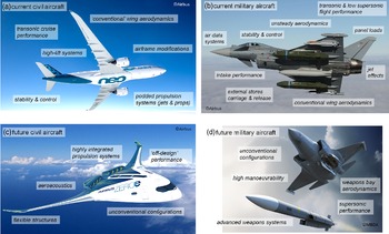
The types of test undertaken in industrial transonic facilities have changed relatively little since the 1950s [Reference Benne48,Reference Dunn71], although the emphasis has gradually been shifting away from routine testing to populate performance and S&C databasesFootnote 22 (e.g. civil aircraft cruise performance), to unconventional configurations, extremes of the flight envelope, and highly-integrated propulsion systems.
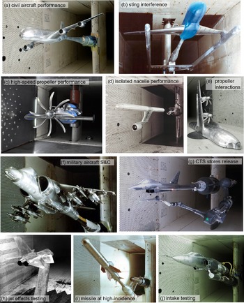
Figure 11 illustrates some examples of current and near-future applications for transonic testing at an industrial scale, all of which would have been familiar to test engineers 30–40 years ago [Reference Blackwell7]. Advances in instrumentation systems have had some impact, particularly optical measurements of model surfaceFootnote 23 properties such as pressureFootnote 24 , temperature and deformation [Reference Davidson, Stokes, Roberts and Quinn72], but the mainstays of testing in large industrial transonic facilities remain the traditional internal sting balance [73] for forces and moments, and the electronic multiplexed pressure scanner for surface pressure distributions. Developments in instrumentation, data acquisition systems, and data reduction methods [Reference Davis96] have contributed to the data productivity trends of Fig. 5, but Fig. 4 suggests that this has been counter-balanced by the shift away from routine performance database building.
Examples of current and near-future applications for transonic testing.

Typical industrial transonic test types include [Reference Pope and Goin5,Reference Blackwell7]:
-
− concept development – aimed at the development and evaluation of a particular aerodynamic concept, for example Hybrid Laminar Flow Control [Reference Lawson, Ciarella and Wong74]. These tests are often of an exploratory nature, making use of an existing model or test rig.
-
− code development – verifying or calibrating theoretical or computational aerodynamic analysis tools, typically using simplified model configurations, but with complex test setups [Reference Blackwell7]. More recently, these activities have moved from addressing stand-alone tools to developing integrated computational and experimental test capabilities [Reference Chanetz9,Reference Watanabe33,Reference Dunn34].
-
− flight vehicleFootnote 25 configuration development – demonstrating and refining a configuration with a defined mission or market. This could be a generic technology demonstration programme, or part of the generation and down-selection of configurations for a specific flight vehicle project. Models are often modular, with a large number of alternative components, but with some geometry simplifications (e.g. faired-over inlets or flow-through nacelles)
-
− mission performance – establishing the aerodynamic performance of a production vehicle throughout its operating range (Mach number, Reynolds number and incidence). This could include both full-span models with an internal balance [Reference Harris75], semi-span models with an external balance, and tests aimed at addressing scalingFootnote 26 [76] as well as performance issues. Individual panels may be balanced for structural loads. Drag measurements for cruise performance are the most demanding form of test in a transonic facility in terms of measurement accuracy and repeatability (Fig. 12(a), (b)), but have become less important as CFD capabilities have improved advances; the focus now tends to be on the extremes of the flight envelope.
Figure 12.Examples of civil and military testing at the aircraft research association [92–Reference Greenwell94].
-
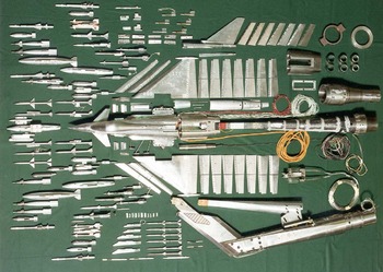
− stability and control (S&C) – establishing the static stability characteristics and control effectiveness of a production vehicle. Force models are complex and test entries tend to be lengthy, with multiple configurations to work through (particularly for military aircraft, Figs 12(f) and 13). Individual surfaces may also be balanced for measurement of actuation loads [Reference Davie77,Reference Muncey and Pote78].
Figure 13.Example of a military aircraft force model [92].
-
− propulsion integration – establishing the installed performance of propulsion systems or their components, and the ‘throttle-dependent’ effect of propulsion flows on configuration aerodynamics [79–Reference McWaters81]. This includes isolated and installed propellers (often on semi-span models) and podded engines for civil aircraft (Fig. 12(c), (d), (e)), and inlet and jet-effects models for military aircraft (Fig. 12(h), (j)). Complete propulsion systems may also be tested [Reference Celestina and Long-Davis82].
-
− weapons integration – supporting the safe and effective deployment of weapons systems from military aircraft. This includes store carriage testing to assess the effects of external carried weapons and tanks on the aerodynamic characteristics of the store and the parent aircraft, store release testing using a Captive Trajectory System [Reference Wood83,Reference Veazey84] (Fig. 12(g)) or occasionally free-drop testingFootnote 27 , and (for recent military aircraft configurations) weapons bay aerodynamics. Fitting balances to stores and pylons for loads measurements can be challenging due to the small size and unsteady flows.
-
− unsteady aerodynamics – encompassing aeroacoustics of propellers [Reference Wood and Newman85] (Fig. 12(c)) and cavities [Reference Roberts86], unsteady pressure forces acting on a model, aeroelastic response of flexible models, and free- and forced-oscillation testing [Reference McConnell87,Reference Jin88]. Dynamic testing of one form or another is becoming a more significant part of the work load at industrial facilities, with current topics of interest including shock-induced buffet [Reference Masini, Timme and Peace89] and gust response [Reference Gomariz-Sancha90] for civil aircraft, and weapons bay aerodynamics and transonic wing-drop [Reference McConnell87] for military aircraft. For unsteady pressure measurements, cost, and reliabilityFootnote 28 of pressure transducers has always been an issue, but Dynamic Pressure Sensitive Paint (DPSP) has the potential to be a game-changer for industrial testing [Reference Davidson, Stokes, Roberts and Quinn72,Reference Davidson, Stokes, Roberts and Quinn91].
-
− miscellaneous aircraft systems and components – for example air data systems, air-to-air refuelling booms, antennae, etc.


4.3 Production testing
For an industrial facility, the test types listed above could all be grouped together as production testing. Ref. [Reference Meija68] describes this as being like the traditional testing that a new graduate would be familiar with, but working at larger scale, higher productivity, higher accuracy, higher repeatability, and (much) higher cost. To this list could also be added shorter timescales, and more demanding data customers.
As a result, test planning and management is a much more complex and contingent process than the neat test programme flow charts in AIAA-R-092 might imply. Elements may run in parallel (e.g. model design and manufacture), or be repeated (e.g. reconsideration of test objectives, or the test plan), as circumstances change. Tests fail, or are compromised, due to facility or model issues, or due to human error. Customers change their minds at the last moment or dispute the costs, and so on. In the face of all this, the test engineer must focus on ensuring that activities that must happen, do happenFootnote 29 ; the absolutely key requirement for an industrial wind tunnel test engineer is therefore flexibility in the face of apparent disaster.
An incomplete list of the typical challenges that a test engineer may face in the progress of a production test includes:
-
− plant failure – most industrial facilities are oldFootnote 30 , and worked hard, so failures of the tunnel plant (e.g. main drive, compressors, cooler, drier), are to be expected [Reference Colantonio95].
-
− model failure – testing at high speeds and at the extremes of the flight envelope puts extreme demands on the model structure. Model failures range from the almost routine loss of minor components (e.g. fasteners and fairings) to the very rare catastrophic break-up of a model. Unfortunately, at high speeds model failures are near-instantaneous, so the best a test engineer can do is to be rigorous in checking the model, and hope that the tunnel debris catcherFootnote 31 does its job.
-
− instrumentation failure – given the complexity of the measurements typically being made in a production test, it is inevitable that elements of the data chain will fail to perform as required. This could range from poor measurement accuracy or poor repeatability, to physical failure or degradation of a sensor — pressure transducers, hot-wires, and balances are common culprits. Instrumentation issues are often elusive, and can escape the attention of both customer and facility test teams; the good production engineer is always suspicious of their data.
-
− data reduction failure – almost every industrial test has unique aspects, so it is usual for data reduction codes to be modified on a test-by-test basis, often at short notice. In these circumstances bugs are to be expected, and having to reprocess data during and/or after a test is not uncommon. Data corrections for wind tunnel interference effects in ventilated test sections can be problematic for unconventional model configurations and test types, particularly for facilities still relying on older semi-empirical methods [Reference Davis96].
-
− flow physics failure – when an expensive test fails to give the results the customer expects, life can become very difficult for the test engineer. Data customers will rarely accept that a test concept was flawed after the fact, so management of expectations prior to testing is a critical skill in production testing. Particular attention also needs to be paid to aspects of the test requirements that impact on extrapolation to full-scale, for example appropriate transition fixing strategies [97].
-
− test matrix changes – establishing and managing a test matrix (or runs list) for a production test is a rolling (and thankless) task for the test engineer. Initial matrices from data customers are almost always optimisticFootnote 32 , and the inevitable changes forced by the harsh realities of testing in an industrial facility are often a source of contention. Many industrial data customers remain wedded to rectangular test matrices, although more flexible techniques such as Modern Design of Experiments [Reference DeLoach98] are beginning to be pulled through from academia.
-
− productivity vs data quality – data productivity in production testing has seen a steady increase in recent years (Fig. 5), due to a combination of improved instrumentation systems and changes to test techniques. However, maintaining this level of output puts significant time pressures on the facility test team which are not generally present in a research or academic environment. In some cases data quality has had to be traded-off against data productivityFootnote 33 ; the challenge for the production test engineer is to maintain control of this trade-off in the face of commercial and management pressures to keep taking data.
-
− tracking costs – an additional burden for the busy test engineer in an industrial facility is the need to keep track of costs during a test entry, often on an hourly basis. Commercial tests are typically charged either by the User Occupancy HourFootnote 34 (UOH), or on a fixed-price Statement of Work (SoW). In the former case, the test customer is the one worrying about costs and productivity; in the latter case it is the facility management doing the worrying.
In facing these challenges, perhaps the most effective mitigation strategy is to recognise that a production test should be a collaborative effort between the customer test team and the facility test team. Commercial pressures and mindsets can make this difficult, but experience shows that better results are obtained when both teams are involved in pre-test planning, post-test data analysis and assessment, and reporting [Reference West37,Reference Madl70].
5.0 Summary
This paper has presented a snapshot of industrial transonic testing in the early 2020s, with the aim of helping new entrants to the field make the step from research work in small-scale university facilities to testing commercial projects in large-scale high-speed industrial facilities.
In addition, a rather surprising picture of the current status of transonic wind tunnels has emerged, which contradicts current received wisdom that the wind tunnel is a dinosaur technology, nearing extinction. Globally, the industrial transonic wind tunnel is undergoing somewhat of a renaissance. Numbers are increasing, investment levels are rising, capabilities are being enhanced, and facilities are busy.
Some salient points from that global picture are:
CFD developments have not had a significant impact on wind tunnel usage for flight vehicle development programmes.
there is currently a very high demand for industrial testing in transonic wind tunnels.
the types of test done in industrial transonic wind tunnels have changed very little over the past 30–40 years, but have become more complex.
numbers of operational industrial transonic and trisonic tunnels are increasing, with recent new-built and reactivated tunnels in China, Korea, and India.
as of 2021 there are 39 industrial transonic and trisonic wind tunnels operational around the world, supported by a population of around 60–70 smaller research facilities.
of the 20 industrial trisonic blowdown tunnels built since the 1950s, only one has ever closed permanently – the rest are still operational.
most major industrial facilities have had some kind of refurbishment or upgrade in the last 20 years.
most countries have a single national aerospace research organisation, and associated research facilities, that provide a technical ecosystem in which their industrial tunnels operate.
From a UK perspective, the picture is less optimistic.
there are only two industrial-scale high-speed wind tunnels in the UK: a continuous transonic tunnel at ARA, and a blowdown trisonic tunnel at BAE.
these two tunnels are old and largely unmodified 1st generation facilities, and both have been in operation for over 60 years.
there are no operational continuous supersonic tunnels in the UK.
there are no supporting transonic research facilities of a significant size and capability in the UK.
there is no supporting national aerospace research organisation in the UK.