1 Introduction
High-speed impacts may occur due to both natural and manmade reasons. The former is often caused by asteroids and meteorites, and one such incident may have led to the extinction of the dinosaurs (Schulte et al. Reference Schulte, Alegret, Arenillas, Arz, Barton, Bown, Bralower, Christeson, Claeys and Cockell2010). The latter transpire during, say, projectile impact, or when deep-penetrating anchors are utilized. Figure 1 shows a torpedo-shaped, heavy deep-penetrating anchor which is released from a height above the seabed and penetrates deep into the seabed due its inertia.
Slow cratering in loose and dense granular beds has been investigated extensively through experiments, computations and theory; see, for example, Katsuragi & Durian (Reference Katsuragi and Durian2007). Both blunt and sharp impactors were considered. High-velocity impacts with blunt impactors have been studied in the context of impact cratering (Melosh Reference Melosh1989).
High-speed penetration of slender bodies is a challenging problem of physics, with a long and venerable history beginning with Robins (Reference Robins and Wilson1742), Euler (Reference Euler1922) and Poncelet (Reference Poncelet1835). Because of its application in ballistics and projectile impact, special attention has been directed towards slender, high-speed impactors into metallic solids (Backman & Goldsmith Reference Backman and Goldsmith1978; Anderson Jr Reference Anderson1978) and soils (Omidvar, Iskander & Bless Reference Omidvar, Iskander and Bless2014). Lately, impacts into seabeds have become important, driven by their utility in deep-penetrating anchoring systems (Medeiros Jr Reference Medeiros2002; O’Loughlin et al. Reference O’Loughlin, Richardson, Randolph and Gaudin2013). In all cases, estimating the projectile’s penetration speed and final penetration depth is of importance.
A typical deep-penetrating anchor. Typical dimensions are
 ${\sim}15$
m in length and
 ${\sim}1$
m in diameter, with a weight of
 ${\sim}1$
ton. Taken with permission from Intermoor.

Most analytical methods estimate penetration depths by employing the following equation to model the impactor’s deceleration:
 $$\begin{eqnarray}\frac{\text{d}u}{\text{d}t}=\unicode[STIX]{x1D6FD}_{1}u^{2}+\unicode[STIX]{x1D6FD}_{2}u+\unicode[STIX]{x1D6FD}_{3},\end{eqnarray}$$
where
 $u$
is the impactor’s speed and
 $\unicode[STIX]{x1D6FD}_{i}$
are parameters found by fitting experiments; see, for example, Allen, Mayfield & Morrison (Reference Allen, Mayfield and Morrison1957a
,Reference Allen, Mayfield and Morrison
b
). The presence of the rate-independent term
 $\unicode[STIX]{x1D6FD}_{3}$
ensures finite-time stoppage. The linear term
 $\unicode[STIX]{x1D6FD}_{2}u$
is discarded when the penetration speeds are high, to recover Poncelet’s equation (Poncelet Reference Poncelet1835). In vertical impacts, if the projectile’s mass is not negligible, the acceleration due to gravity is explicitly included.
Theoretical attempts have been made to develop expressions for the constants
 $\unicode[STIX]{x1D6FD}_{1},\unicode[STIX]{x1D6FD}_{2}$
and
 $\unicode[STIX]{x1D6FD}_{3}$
for slender, high-speed impactors from fundamental principles. When the impact is on metals, these attempts have utilized hydrodynamic models (Birkhoff et al.
Reference Birkhoff, MacDougall, Pugh and Taylor1948; Alekseevskii Reference Alekseevskii1966; Tate Reference Tate1967, Reference Tate1969, Reference Tate1978, Reference Tate1986a
,Reference Tate
b
; Yarin, Rubin & Roisman Reference Yarin, Rubin and Roisman1995) or spherical and cylindrical cavity expansion methods (Hopkins Reference Hopkins, Sneddon and Hill1960; Goodier Reference Goodier1965; Hill Reference Hill1980; Masri & Durban Reference Masri and Durban2009; Warren Reference Warren2016). Impact into soils (Forrestal & Luk Reference Forrestal and Luk1992; Durban & Masri Reference Durban and Masri2004; Omidvar et al.
Reference Omidvar, Iskander and Bless2014), ceramics (Satapathy Reference Satapathy2001) and rocks (Kipp & Longscope Reference Kipp and Longscope1973) are almost exclusively addressed through cavity expansion methods. However, cavity expansion may not always be accurate as it does not account for the non-spherical nature of the projectile’s nose (Rubin Reference Rubin2016), because of which it can fail to give adequate results even in the case of static penetration of long piles (Baligh Reference Baligh1985).
The aim of this work is develop a hydrodynamic-like model for high-speed impact of slender bodies into frictional geomaterials such as soils and clays. Besides Sharma & Huppert (Reference Sharma, Huppert, Gupta and Manzhirov2008), no such investigation has yet been attempted. We will model these geomaterials within the general framework of pressure- and strain-rate-dependent Bingham fluids – which are non-smooth, complex fluids that flow once the stress in the material violates a yield criterion. We will demonstrate the utility of our approach in the context of deep-penetrating anchors, where our predictions of the anchor’s penetration depth and velocity history match well with laboratory and field experiments. We consider vertically downward impact, so that the impactor’s large weight affects the penetration process.
2 Mathematical modelling
Figure 2(a) shows a schematic of the system. The impactor’s deceleration is given by
 $$\begin{eqnarray}a=\dot{u}=g-\frac{N(t,h)}{m},\end{eqnarray}$$
where
 $N$
is the total upward vertical force exerted by the surrounding material on the impactor, which changes with time
 $t$
and penetration depth
 $h$
,
 $g$
is the acceleration due to gravity,
 $m$
is the impactor’s mass, and
 $u(t)$
is its penetration speed (positive downwards). The force
 $N$
is found by integrating the vertical traction
 $T$
over the impactor’s surface:
 $$\begin{eqnarray}N(t,h)=\int T\,\text{d}A,\end{eqnarray}$$
where, at any point on the impactor’s surface,
 $$\begin{eqnarray}T=\unicode[STIX]{x1D70E}_{nn}\sin \unicode[STIX]{x1D711}+\unicode[STIX]{x1D70F}\cos \unicode[STIX]{x1D711},\end{eqnarray}$$
in terms of the normal (
 $\unicode[STIX]{x1D70E}_{nn}$
) and tangential (
 $\unicode[STIX]{x1D70F}$
) tractions and the angle
 $\unicode[STIX]{x1D711}$
shown in figure 2(a). The main challenge is to estimate
 $\unicode[STIX]{x1D70E}_{nn}$
and
 $\unicode[STIX]{x1D70F}$
.
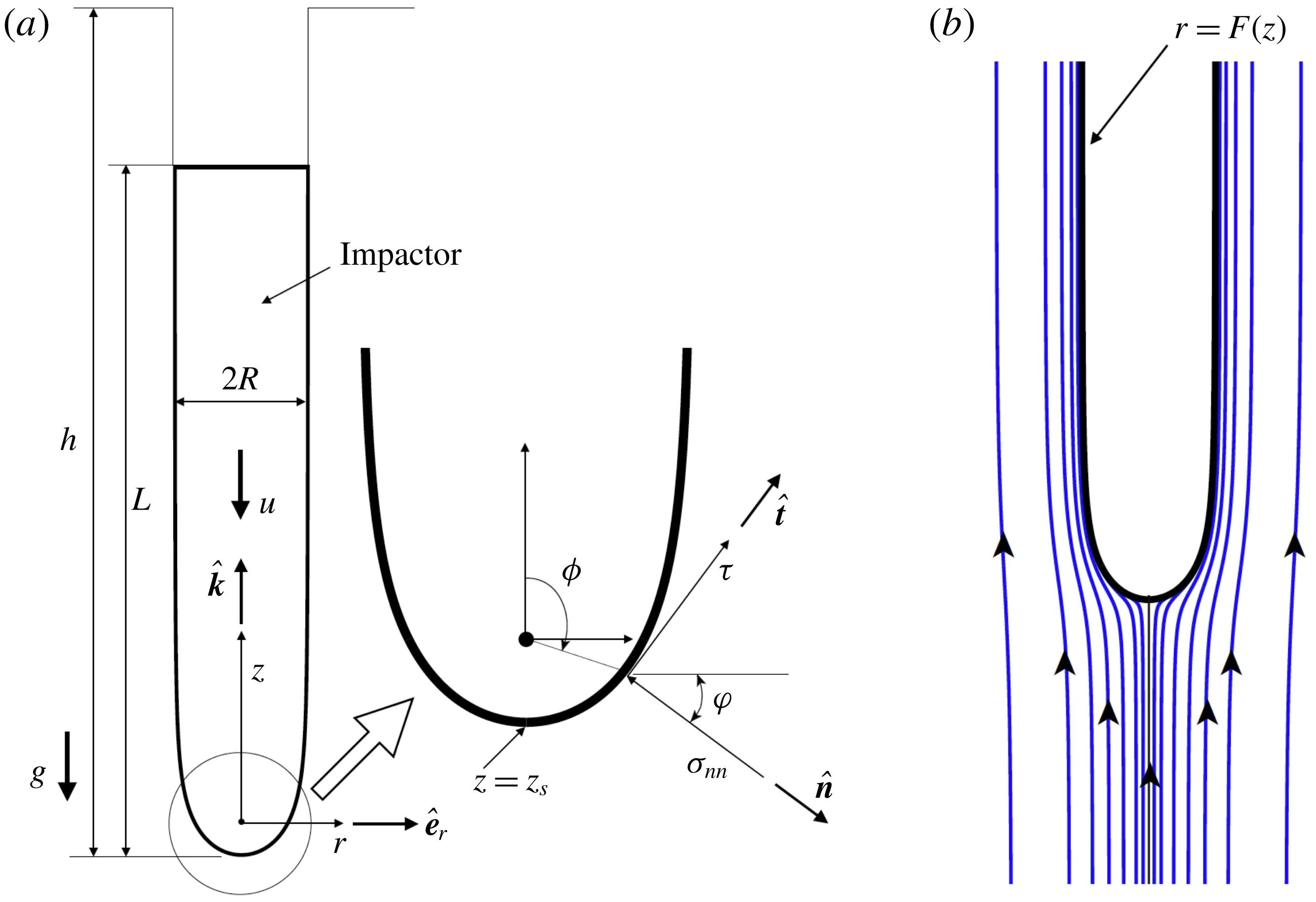
Our approach now has the following main steps: (i) we first propose a model for the flow field
 $\boldsymbol{u}$
for the impacted material as it yields and flows around the impactor. Far away from the impactor the material will remain intact (unyielded). (ii) Knowledge of
 $\boldsymbol{u}$
will then allow us to compute the strain-rate field
 $\unicode[STIX]{x1D63F}=\{\unicode[STIX]{x1D735}\boldsymbol{u}+(\unicode[STIX]{x1D735}\boldsymbol{u})^{\text{T}}\}/2$
in the impacted material. (iii) We next select constitutive laws appropriate for materials such as soils and clays. (iv) We combine the constitutive law with the computed strain-rate field and the linear momentum balance to obtain the stress field
 $\unicode[STIX]{x1D748}$
in the impacted material. From
 $\unicode[STIX]{x1D748}$
the total force
 $N$
on the impactor is found through (2.3) and (2.2), and (2.1) may then be integrated to obtain the evolutions of the impactor’s penetration and velocity.
2.1 Flow
Slender impactors have a cylindrical shaft (shank) capped by a curved nose. The flow of the material being penetrated by such impactors, relative to the impactor, can be approximated as a superposition of point sources upon a uniform background flow. In the simplest case (Tate Reference Tate1978; Yarin et al.
Reference Yarin, Rubin and Roisman1995), for an impactor penetrating at speed
 $u(t)$
at time
 $t$
, the relative velocity field of the impacted material may be obtained from the stream function
 $$\begin{eqnarray}\unicode[STIX]{x1D6F9}(r,z,t)=(R^{2}\cos \unicode[STIX]{x1D719}-2r^{2})u(t)/4,\end{eqnarray}$$
where
 $r$
and
 $z$
are as in figure 2(a),
 $\unicode[STIX]{x1D719}=\arctan (r/z)$
and
 $R$
is the radius of the impactor’s shank. The stream function
 $\unicode[STIX]{x1D6F9}$
represents the superposition of the flow field due to a growing spherical cavity of volumetric strength
 $\unicode[STIX]{x03C0}u(t)R^{2}$
per unit time and a background flow of rate
 $u(t)$
. Figure 2(b) shows the streamlines associated with (2.4) in the frame of the impactor. Note that, in a fixed frame, it is the impactor that penetrates at
 $u(t)$
which, in turn, is controlled by (2.1).
From (2.4), with
 $\tilde{r}=\sqrt{r^{2}+z^{2}}$
, we obtain velocity and strain-rate fields in the impacted material relative to the impactor, respectively,
 $$\begin{eqnarray}\boldsymbol{u}(r,z,t)=u(t)(\sin \unicode[STIX]{x1D719}\,\hat{\boldsymbol{e}}_{r}+\cos \unicode[STIX]{x1D719}\,\hat{\boldsymbol{k}})\frac{R^{2}}{4\tilde{r}^{2}}+u(t)\hat{\boldsymbol{k}},\end{eqnarray}$$
and
 $$\begin{eqnarray}\displaystyle \unicode[STIX]{x1D63F}(r,z,t) & = & \displaystyle \frac{u(t)R^{2}}{4\tilde{r}^{3}}(\cos ^{2}\unicode[STIX]{x1D719}-2\sin ^{2}\unicode[STIX]{x1D719})\hat{\boldsymbol{e}}_{r}\otimes \hat{\boldsymbol{e}}_{r}+\frac{u(t)R^{2}}{4\tilde{r}^{3}}\hat{\boldsymbol{e}}_{\unicode[STIX]{x1D703}}\otimes \hat{\boldsymbol{e}}_{\unicode[STIX]{x1D703}}\nonumber\\ \displaystyle & & \displaystyle +\,\frac{u(t)R^{2}}{4\tilde{r}^{3}}(\sin ^{2}\unicode[STIX]{x1D719}-2\cos ^{2}\unicode[STIX]{x1D719})\hat{\boldsymbol{k}}\otimes \hat{\boldsymbol{k}}-\frac{3u(t)R^{2}}{4\tilde{r}^{3}}\sin \unicode[STIX]{x1D719}\cos \unicode[STIX]{x1D719}(\hat{\boldsymbol{e}}_{r}\otimes \hat{\boldsymbol{k}}+\hat{\boldsymbol{k}}\otimes \hat{\boldsymbol{e}}_{r}),\nonumber\\ \displaystyle & & \displaystyle\end{eqnarray}$$
where
 $\otimes$
denotes the outer product. The relative acceleration field
 $\boldsymbol{a}(r,z,t)=a_{r}\hat{\boldsymbol{e}}_{r}+a_{\unicode[STIX]{x1D703}}\hat{\boldsymbol{e}}_{\unicode[STIX]{x1D703}}$
is obtained by computing
 $\unicode[STIX]{x2202}\boldsymbol{u}/\unicode[STIX]{x2202}t+\boldsymbol{u}\boldsymbol{\cdot }\unicode[STIX]{x1D735}\boldsymbol{u}$
. In particular,
 $$\begin{eqnarray}a_{r}(r,z,t)=\frac{R^{2}r}{4\tilde{r}^{3}}\left\{\dot{u}(t)-\frac{3z}{\tilde{r}^{2}}u(t)^{2}-\frac{R^{2}}{2\tilde{r}^{3}}u(t)^{2}\right\}.\end{eqnarray}$$
We note that (i) strain rates change with the impactor’s speed
 $u(t)$
, (ii) far from the impactor the flow field becomes uniform, i.e.
 $\boldsymbol{u}\rightarrow u(t)\hat{\boldsymbol{k}}$
when
 $\tilde{r}\gg R$
, and (iii) the strain-rate tensor’s magnitude
 $|\unicode[STIX]{x1D63F}|=\sqrt{\unicode[STIX]{x1D60B}_{ij}\unicode[STIX]{x1D60B}_{ij}}=\sqrt{6}uR^{2}/4\tilde{r}^{3}$
so that, at any
 $z$
,
 $|\unicode[STIX]{x1D63F}|\sim r^{-3}$
as
 $r\rightarrow \infty$
.
The zero-velocity streamline, which emanates from the stagnation point
 $z=z_{s}=-R/2$
, is an ovoid of Rankine:
 $$\begin{eqnarray}r=F(z)=\left\{\left(R^{2}-z^{2}+z\sqrt{z^{2}+2R^{2}}\right)/2\right\}^{1/2};\end{eqnarray}$$
this is shown in figure 2(b). We observe that the zero-velocity streamline imitates the shape of an impactor with a near-cylindrical shank and a curved nose very well. In fact, if the impactor’s shape was given by (2.8), then the flow would satisfy our expectation that the material velocity normal to the impactor’s surface vanishes. Of course, general torpedo-shaped impactors (for example, figure 1) will not strictly satisfy (2.8). Subsequently, we will ignore these differences in shape, and take the impactor’s shape to be the profile generated by (2.8). This assumes that modelling the impactor’s exact profile may not greatly affect its dynamics. This simplifying assumption is also a practical one, considering that the complex rheology of geomaterials is itself not well understood and mathematical descriptions incorporate many idealizations. Finally, we note that, when crucial, it is possible to systematically improve our approximation of the impactor’s shape by introducing point vortex sources (Tate Reference Tate1986a ,Reference Tate b ).
The kinematic description (2.5) works well given the impactor’s speed and slenderness, and because material flow around the impactor is severely confined. However, (2.5) will be unable to capture flow detachment or changes in the flow introduced by fluid friction. Nevertheless, we surmise that the kinematic description (2.5) will yield useful answers, at least at leading order, for any rheology, provided the impactor is slender and penetrates at a fast rate; for example, this held true for projectile impact into metals (Yarin et al. Reference Yarin, Rubin and Roisman1995).
2.2 Rheology
The next step is to select appropriate constitutive models for geomaterials such as soil and clay. Soils and clays may both be modelled as pressure-dependent Bingham fluids (Oldroyd Reference Oldroyd1947; Prager Reference Prager1961). Such fluids have a yield criterion that separates solid- and fluid-like behaviour. Yielding in soils depends on the local pressure, but this is not so in clays, wherein yielding is regulated by a maximum shear strength
 $K$
. In either case, the rheology postyield may be represented as
 $$\begin{eqnarray}\unicode[STIX]{x1D748}=-p\mathbf{1}+\sqrt{2}K\unicode[STIX]{x1D63F}/|\unicode[STIX]{x1D63F}|,\end{eqnarray}$$
where
 $\unicode[STIX]{x1D748}$
is the postyield stress tensor,
 $p=-(\text{tr}\,\unicode[STIX]{x1D748})/3$
is the pressure and
 $\mathbf{1}$
is the identity tensor. The constitutive law above is rate-independent, and should be compared with the usual Amontons–Coulomb friction law, with
 $K$
playing the role of a ‘friction coefficient’.
The shear strength in water-saturated clays increases with vertical depth. For simplicity we set
 $$\begin{eqnarray}K=R_{f}k(h-z),\end{eqnarray}$$
where
 $R_{f}$
accounts for the rate dependence of clay (Casagrande & Wilson Reference Casagrande and Wilson1951) and the shear strength gradient
 $k$
models the variation with depth of the maximum shear stress. For example, in seabed clay
 $k\approx 1.5~\text{kPa}~\text{m}^{-1}$
(Freeman, Murray & Schüttenhelm Reference Freeman, Murray and Schüttenhelm1988). Following Mitchell & Soga (Reference Mitchell and Soga2005) we take
 $$\begin{eqnarray}R_{f}=1+\unicode[STIX]{x1D706}\max \{\ln |\dot{\unicode[STIX]{x1D6FE}}/\dot{\unicode[STIX]{x1D6FE}}_{ref}|,0\},\end{eqnarray}$$
where the rate parameter
 $\unicode[STIX]{x1D706}$
is a constant that estimates the increase in the clay’s strength per log cycle, and
 $\dot{\unicode[STIX]{x1D6FE}}$
and
 $\dot{\unicode[STIX]{x1D6FE}}_{ref}$
are magnitudes of the actual and reference strain rates, respectively. We will estimate
 $\dot{\unicode[STIX]{x1D6FE}}$
as
 $u/(2R)$
, where
 $u$
is the impactor’s penetration speed. Laboratory tests (O’Loughlin et al.
Reference O’Loughlin, Richardson, Randolph and Gaudin2013) on clay estimate
 $\unicode[STIX]{x1D706}$
to be in the range 0.2–1 for
 $\dot{\unicode[STIX]{x1D6FE}}_{ref}=0.17$
, but suggest that in the field
 $\unicode[STIX]{x1D706}$
may lie within 0.15–0.2. Henceforth, we will set
 $\dot{\unicode[STIX]{x1D6FE}}_{ref}=0.17$
in all our computations. Finally, the ‘max’ in (2.11) is introduced to ensure that rate effects are included only if the strain rate
 $\dot{\unicode[STIX]{x1D6FE}}$
is greater than the reference strain rate
 $\dot{\unicode[STIX]{x1D6FE}}_{ref}$
.
2.3 Water-saturated clays
The computation of the impactor’s dynamics will now be demonstrated in the specific case of the penetration into seabeds of deep-penetrating anchors of the kind shown in figure 1. For this, we will employ the rheology of seabed clay as modelled through (2.9)–(2.11). Analysis of impacts into soils would follow the same procedure, but with a different rheology, and this will be taken up in the future.
The stress tensor during seabed penetration is found by combining (2.6) and (2.9):
 $$\begin{eqnarray}\displaystyle \unicode[STIX]{x1D748} & = & \displaystyle -p\mathbf{1}+\frac{K}{\sqrt{3}}\{(\cos ^{2}\unicode[STIX]{x1D719}-2\sin ^{2}\unicode[STIX]{x1D719})\hat{\boldsymbol{e}}_{r}\otimes \hat{\boldsymbol{e}}_{r}+\boldsymbol{e}_{\unicode[STIX]{x1D703}}\otimes \hat{\boldsymbol{e}}_{\unicode[STIX]{x1D703}}\nonumber\\ \displaystyle & & \displaystyle +\,(\sin ^{2}\unicode[STIX]{x1D719}-2\cos ^{2}\unicode[STIX]{x1D719})\hat{\boldsymbol{k}}\otimes \hat{\boldsymbol{k}}-3\sin \unicode[STIX]{x1D719}\cos \unicode[STIX]{x1D719}(\hat{\boldsymbol{e}}_{r}\otimes \hat{\boldsymbol{k}}+\hat{\boldsymbol{k}}\otimes \hat{\boldsymbol{e}}_{r})\!\},\end{eqnarray}$$
where
 $\hat{\boldsymbol{e}}_{r}$
and
 $\hat{\boldsymbol{k}}$
are shown in figure 2(a) and
 $\hat{\boldsymbol{e}}_{\unicode[STIX]{x1D703}}=\hat{\boldsymbol{k}}\times \hat{\boldsymbol{e}}_{r}$
. The normal traction
 $\unicode[STIX]{x1D70E}_{nn}$
to be utilized in (2.3) is given by
 $\hat{\boldsymbol{n}}\boldsymbol{\cdot }\unicode[STIX]{x1D748}\boldsymbol{\cdot }\hat{\boldsymbol{n}}$
, where
 $\hat{\boldsymbol{n}}$
is the normal to the anchor’s surface defined by (2.8); see figure 2(a). However, the tangential traction
 $\unicode[STIX]{x1D70F}$
in (2.3) is not estimated well by
 $\hat{\boldsymbol{n}}\boldsymbol{\cdot }\unicode[STIX]{x1D748}\boldsymbol{\cdot }\hat{\boldsymbol{t}}$
, where
 $\hat{\boldsymbol{t}}$
is the unit tangent in the
 $\hat{\boldsymbol{e}}_{r}-\hat{\boldsymbol{k}}$
plane, as the velocity field (2.5) corresponds to an inviscid flow. Hence, we postulate that
 $\unicode[STIX]{x1D70F}$
is proportional to the maximum shear strength
 $K$
, i.e.
 $$\begin{eqnarray}\unicode[STIX]{x1D70F}=\unicode[STIX]{x1D6FC}K,\end{eqnarray}$$
where the adhesion factor
 $\unicode[STIX]{x1D6FC}$
is obtained from experiments – for example, Kaolin clay has
 $\unicode[STIX]{x1D6FC}=0.4$
(O’Loughlin et al.
Reference O’Loughlin, Richardson, Randolph and Gaudin2013). Combining (2.3) with (2.8), (2.12) and (2.13), we obtain
 $$\begin{eqnarray}T(z,t)=\frac{F^{\prime }(2\unicode[STIX]{x1D70E}_{rz}F^{\prime }-\unicode[STIX]{x1D70E}_{rr}-\unicode[STIX]{x1D70E}_{zz}F^{\prime 2})}{(1+F^{\prime 2})^{3/2}}+\frac{\unicode[STIX]{x1D6FC}K}{\sqrt{1+F^{\prime 2}}},\end{eqnarray}$$
where
 $F^{\prime }=\text{d}F/\text{d}z$
and
 $T$
changes with time and location
 $z$
along the anchor. The first term on the right captures the contribution to
 $T$
from normal traction, while the second term is due to tangential traction. The total vertical force
 $N$
on the anchor at any time
 $t$
may now be obtained from (2.2):
 $$\begin{eqnarray}N(t)=2\unicode[STIX]{x03C0}\int _{z_{s}}^{L}T(z,t)F(z)\,\text{d}z,\end{eqnarray}$$
where
 $z=z_{s}$
locates the anchor’s tip; see figure 2(a).
To express
 $\unicode[STIX]{x1D748}$
, and hence
 $N$
, only in terms of the material parameters of the seabed and the anchor’s geometry and dynamics, we need to find the pressure
 $p$
. For this, we consider linear momentum balance in the
 $r$
direction:
 $$\begin{eqnarray}\frac{\unicode[STIX]{x2202}\unicode[STIX]{x1D70E}_{rr}}{\unicode[STIX]{x2202}r}+\frac{\unicode[STIX]{x2202}\unicode[STIX]{x1D70E}_{rz}}{\unicode[STIX]{x2202}z}+\frac{\unicode[STIX]{x1D70E}_{rr}-\unicode[STIX]{x1D70E}_{\unicode[STIX]{x1D703}\unicode[STIX]{x1D703}}}{r}=\unicode[STIX]{x1D70C}_{s}a_{r},\end{eqnarray}$$
where
 $\unicode[STIX]{x1D70C}_{s}$
is the density of seabed clay. We then utilize (2.7) and (2.12) to obtain
 $$\begin{eqnarray}\frac{\unicode[STIX]{x2202}p}{\unicode[STIX]{x2202}r}=-\unicode[STIX]{x1D70C}_{s}\frac{R^{2}r}{4\tilde{r}^{3}}\left\{\dot{u}(t)-\frac{3z}{\tilde{r}^{2}}u(t)^{2}-\frac{R^{2}}{2\tilde{r}^{3}}u(t)^{2}\right\}-\frac{\sqrt{3}Kr}{\tilde{r}^{2}}\left(2+\frac{z}{K}\frac{\unicode[STIX]{x2202}K}{\unicode[STIX]{x2202}z}\right),\end{eqnarray}$$
where the last term is due to
 $K$
’s variation with depth and we recall that
 $\tilde{r}=\sqrt{r^{2}+z^{2}}$
. At any time, with the anchor’s deceleration
 $\dot{u}$
provisionally known from (2.1), the above equation is integrated along constant
 $z$
-lines from the anchor’s surface at
 $r=F(z)$
to the plastic boundary at
 $r=r_{p}(z)$
– beyond which the clay remains solid and does not flow – to obtain the pressure
 $p_{a}:=p|_{r=F(z)}$
on the anchor’s surface. Utilizing (2.10), we find
 $$\begin{eqnarray}p_{a}=\unicode[STIX]{x1D70C}_{s}g(h-z)+\left[-\frac{\unicode[STIX]{x1D70C}_{s}R^{2}\dot{u}}{4\tilde{r}}+\unicode[STIX]{x1D70C}_{s}\left(\frac{zR^{2}}{4\tilde{r}^{3}}+\frac{R^{4}}{32\tilde{r}^{4}}\right)u^{2}+\sqrt{3}K\frac{2h-3z}{h-z}\ln \tilde{r}\right]_{r=F(z)}^{r=r_{p}(z)},\end{eqnarray}$$
where we have taken the far-field pressure to be lithostatic, i.e. due to the seabed’s weight,
 $z=h$
is the location of the sea floor with respect to the anchor (figure 2
a) and
 $[f(r)]_{r=F(z)}^{r=r_{p}(z)}=f(r_{p})-f(F)$
for any function
 $f(r)$
. The first term in the brackets in (2.18) contributes to the added mass arising from the clay’s inertia while the second leads to the coefficient
 $\unicode[STIX]{x1D6FD}_{1}$
in (1.1). Finally, the sea’s weight acts on both the seabed and the anchor and may, therefore, be ignored.
To utilize (2.18) the location
 $r_{p}(z)$
of the plastic boundary has to be estimated. By definition the seabed clay does not yield for
 $r>r_{p}$
. An exact estimate for the plastic boundary requires the solution for the equilibrium of the unyielded material. We do not pursue this complex plasticity calculation, given the relative simplicity of our overall description, and because material behaviour and system geometry are rather ill-constrained in actual scenarios. Instead, we note from (2.6) that the strain-rate’s magnitude drops off as
 $r^{-3}$
for large
 $r$
, so that we expect the seabed to be relatively undisturbed not too far from the anchor. We then set
 $r_{p}/R\approx 4$
, a value which is consistent with the large-deformation, elasto-plastic computations of Sabetamal et al. (Reference Sabetamal, Carter, Nazem and Sloan2016), and with estimates derived from the analytical solution of the dynamical expansion of a spherical cavity in pressure-dependent materials (Durban & Masri Reference Durban and Masri2004).
3 Results and discussion
Utilizing (2.12), (2.13) and (2.18) in (2.14) allows us to compute
 $N$
from (2.15) at any given time
 $t$
. Substituting
 $N$
into (2.1) then yields a second-order differential equation for the penetration depth
 $h$
. This equation, after non-dimensionalization is
 $$\begin{eqnarray}(1+2\unicode[STIX]{x1D700}^{2}c_{m}\overline{m}_{a})\ddot{\overline{h}}=\overline{g}\{1-c_{f}(\unicode[STIX]{x1D700}\overline{N}_{n}+\overline{N}_{t})\},\end{eqnarray}$$
where
 $\overline{m}_{a},\overline{N}_{n}$
and
 $\overline{N}_{t}$
are, respectively, the scaled added mass, and contributions from the normal and tangential tractions to
 $N$
;
 $\overline{h}=h/L$
is the scaled depth of penetration; and differentiation is with respect to scaled time
 $\overline{t}=t/(U_{R}^{2}/L^{2})$
, with
 $U_{R}$
being a reference speed (for example, the impact speed
 $U_{0}$
); and
 $\unicode[STIX]{x1D700}=R/L$
,
 $c_{m}=\unicode[STIX]{x1D70C}_{s}\unicode[STIX]{x03C0}R^{2}L/m$
,
 $\overline{g}=gL/U_{R}^{2}$
and
 $c_{f}=2\unicode[STIX]{x03C0}RLK/mg$
are, respectively, the anchor’s slenderness ratio, the scaled mass of the displaced clay, the reduced acceleration due to gravity, and the ratio of the drag force on the anchor, were the maximum shear strength of the clay to act upon it, to the anchor’s weight. The values of
 $\overline{N}_{n},\overline{N}_{t}$
and
 $\overline{m}_{a}$
are obtained from quadratures, respectively,
 $$\begin{eqnarray}\displaystyle & \displaystyle \overline{N}_{t}=\int _{\overline{z}_{s}}^{1}\frac{\unicode[STIX]{x1D6FC}\overline{F}\,\text{d}\unicode[STIX]{x1D709}}{\sqrt{1+\unicode[STIX]{x1D700}^{2}\overline{F}^{\prime 2}}}, & \displaystyle\end{eqnarray}$$
 $$\begin{eqnarray}\displaystyle & \displaystyle \overline{N}_{n}=\int _{\overline{z}_{s}}^{1}\frac{-\overline{\unicode[STIX]{x1D70E}}_{rr}+2\overline{\unicode[STIX]{x1D70E}}_{rz}\overline{F}^{\prime }-\unicode[STIX]{x1D700}^{2}\overline{\unicode[STIX]{x1D70E}}_{zz}\overline{F}^{\prime 2}}{(1+\unicode[STIX]{x1D700}^{2}\overline{F}^{\prime 2})^{3/2}}\,\text{d}\unicode[STIX]{x1D709} & \displaystyle\end{eqnarray}$$
and
 $$\begin{eqnarray}\overline{m}_{a}=\int _{\overline{z}_{s}}^{1}\frac{\overline{a}_{1}\overline{F}\overline{F}^{\prime }\,\text{d}\unicode[STIX]{x1D709}}{\sqrt{1+\unicode[STIX]{x1D700}^{2}\overline{F}^{\prime 2}}},\end{eqnarray}$$
in terms of the appropriately scaled components of the stress tensor
 $\unicode[STIX]{x1D748}$
given in (2.12),
 $\overline{z}=z_{s}/L$
,
 $\unicode[STIX]{x1D709}=z/L$
,
 $\overline{F}=F/R$
,
 $\overline{F}^{\prime }=\text{d}\overline{F}/\text{d}\unicode[STIX]{x1D709}$
, and
 $\overline{a}_{1}=\unicode[STIX]{x1D700}R\{(\unicode[STIX]{x1D709}^{2}+\overline{F}^{2})^{-1/2}-(\unicode[STIX]{x1D709}^{2}+\overline{r}_{p}^{2})^{-1/2}\}/4$
with
 $\overline{r}_{p}=r_{p}/R$
. When non-dimensionalizing
 $\unicode[STIX]{x1D748}$
’s components, the dimensionless groups
 $\unicode[STIX]{x1D70C}_{s}gL/K$
(scaled lithostatic pressure) and
 $\unicode[STIX]{x1D70C}_{s}u^{2}/K$
(scaled clay’s inertia) arise naturally.
Equation (3.1) may now be integrated for a given impact speed at
 $\overline{h}=0$
to until the anchor comes to a stop to find the evolutions of the penetration speed and depth. Figure 3 shows the results for a typical deep-penetrating anchor. From figure 3 we observe that the anchor’s penetration speed initially grows due to gravity overcoming the relatively low seabed resistance. As the anchor penetrates further, the seabed’s resistance increases due to growth in both the shear strength and the lithostatic pressure. This causes the anchor’s speed to reach a maximum, after which it decelerates to a stop. This maximum is reached earlier for anchors whose impact speed
 $U_{0}$
is greater, as the seabed’s shear resistance is elevated at higher strain rates; cf. (2.10) and (2.11). For the same reason, figure 3(a) shows that anchors with larger
 $U_{0}$
stop earlier. However, as expected, faster impacting anchors penetrate deeper; see figure 3(b).
Scaled penetration speed
 $\overline{u}=u/U_{R}$
of an anchor as function of (a) scaled time
 $\overline{t}$
, and (b) scaled depth of penetration
 $\overline{h}$
with time increasing along the curves as indicated. The reference speed
 $U_{R}=30~\text{m}~\text{s}^{-1}$
. Several scaled impact speeds
 $\overline{U}_{0}$
are explored and we show
 $U_{0}$
in
 $\text{m}~\text{s}^{-1}$
next to its associated curve. For the anchor: mass
 $m=100$
metric tons; radius
 $R=0.6$
m; length
 $L=15$
m. For the seabed: density
 $\unicode[STIX]{x1D70C}_{s}=2000~\text{kg}~\text{m}^{-3}$
; adhesion factor
 $\unicode[STIX]{x1D6FC}=0.4$
; rate parameter
 $\unicode[STIX]{x1D706}=0.2$
; shear strength gradient
 $k=1500~\text{kPa}~\text{m}^{-1}$
. These values are representative of deep-penetrating anchors and of seabeds made of Kaolin clay (O’Loughlin et al.
Reference O’Loughlin, Richardson, Randolph and Gaudin2013).

We saw in (2.14) that both normal and tangential traction on the anchor’s surface contribute to the total force resisting the anchor’s penetration. Computations reveal that the resistance due to shear and normal tractions are for the most parts – except when the anchor reaches its greatest penetration speed – comparable, with the former always being greater. Both achieve their largest value when the anchor reaches its peak penetration speed. This is expected because of the dependence of the maximum shear strength
 $K$
on strain rate, which, in turn, is regulated by the penetration speed. Because the shear contribution depends directly on
 $K$
(cf. (2.13)) while the normal contribution is influenced by
 $K$
only through the stresses (cf. (2.12)), at peak penetration speed, the former can, at high impact speeds, become nearly twice the latter. As the anchor slows down the shear contribution reduces rapidly to come close to that of the normal traction. Finally, we note that the anchor’s dynamics depend crucially on the choice of the adhesion factor
 $\unicode[STIX]{x1D6FC}$
and
 $\unicode[STIX]{x1D706}$
, making their careful characterization important. Here we utilize values consistent with available experimental data.
Figure 4 compares our theoretical predictions with field data from the Tyro 86 penetrator experiments of Freeman et al. (Reference Freeman, Murray and Schüttenhelm1988) conducted in the Atlantic Ocean at Great Meteor East. The anchor and seabed parameters follow Freeman et al. (Reference Freeman, Murray and Schüttenhelm1988). The lower value of the adhesion factor
 $\unicode[STIX]{x1D6FC}$
and the choice of the rate parameter
 $\unicode[STIX]{x1D706}$
are consistent with the characterization experiments of, respectively, Baudet & Ho (Reference Baudet and Ho2004) and Low et al. (Reference Low, Randolph, DeJong and Yafrate2004). We investigate both the evolution of the penetration speed
 $u$
with depth
 $h$
and the change in the final penetration depth
 $h_{f}$
with impact speed
 $U_{0}$
. Figure 4(a) shows very good agreement of
 $u$
’s evolution with
 $h$
. There is initial mismatch, which we suspect is due to the flow field (2.5) not being a good model of the flow of the impacted material during the initial stages of the impact, especially at high
 $U_{0}$
. It is possible that the material flow at the beginning of the impact is less constrained than assumed by (2.5). At the same time, figure 4(b) shows excellent match for the final penetration depth. We note that experiment 8612 does not match predictions well, and we trace it to the anomalous deviation in the data at
 $h\approx 40$
m in comparison with the data of experiment 8610.
(a) Comparison of predicted (solid lines) evolution of penetration speed with penetration depth and field data (stars) obtained by Freeman et al. (Reference Freeman, Murray and Schüttenhelm1988). Numbers identify experiments. The mass
 $m$
of the impactor is noted alongside in brackets. (b) Comparison of predicted (filled circles) final penetration depth with impact speed and field data (open circles) of Freeman et al. (Reference Freeman, Murray and Schüttenhelm1988). The parameters utilized were:
 $\unicode[STIX]{x1D70C}=8000~\text{kg}~\text{m}^{-3}$
,
 $R=1.78$
m,
 $L=3.56$
m,
 $\unicode[STIX]{x1D70C}_{s}=1400~\text{kg}~\text{m}^{-3}$
,
 $\unicode[STIX]{x1D6FC}=0.22$
,
 $\unicode[STIX]{x1D706}=0.23$
and
 $k=1500~\text{kPa}~\text{m}^{-1}$
.

Finally, in figure 5 we compare our theoretical predictions of the final penetration depth
 $h_{F}$
, given the impact speed
 $U_{0}$
, with
 $h_{F}$
estimated by O’Loughlin et al. (Reference O’Loughlin, Richardson, Randolph and Gaudin2013) from extensive centrifuge experiments. In these experiments, centrifuges were used to create bed conditions similar to geophysical situations by augmenting the effective acceleration field acting upon the impacted bed to
 $200g$
. The measured depth was then multiplied by 200 to estimate actual penetration
 $h_{F}$
in the field. We find a good match, although theory tends to generally overpredict the penetration depth when
 $h_{F}\gtrapprox 15$
m. This overprediction is explained by the greater-than-linear increase with depth of the shear strength
 $K$
in centrifuge experiments for
 $h\gtrsim 15$
m (O’Loughlin, Randolph & Richardson Reference O’Loughlin, Randolph and Richardson2004, figure 5).
Comparison of predicted (solid lines) final penetration depth with impact speed and estimated from centrifuge experiments (open circles) by O’Loughlin et al. (Reference O’Loughlin, Richardson, Randolph and Gaudin2013). The anchor parameters are shown in the plot. The material parameters of clay used in experiments were (O’Loughlin et al.
Reference O’Loughlin, Randolph and Richardson2004, Reference O’Loughlin, Richardson, Randolph and Gaudin2013):
 $\unicode[STIX]{x1D70C}_{s}=2600~\text{kg}~\text{m}^{-3}$
,
 $\unicode[STIX]{x1D6FC}=0.4$
,
 $\unicode[STIX]{x1D706}=0.42$
and
 $k=1300~\text{kPa}~\text{m}^{-1}$
.

4 Conclusion
We have proposed a model for the high-speed impact of slender bodies into non-smooth, complex fluids. The model has the potential to incorporate a variety of constitutive laws. We verified this for clayey seabeds by investigating the impact of a deep-penetrating anchor. We achieved an excellent match between theory and experiments, which is very encouraging given the model’s simplicity. Several avenues are available for improvement. First, this is a leading-order theory, in that the stresses are essentially due to the expansion of a spherical cavity. Effects of the impactor’s actual shape on the stresses may be systematically included by superposing several flow fields, as in Tate (Reference Tate1986a
,Reference Tate
b
). Second, more accurate strength profiles can be utilized to characterize
 $K$
in (2.10). Finally, the utility of the current modelling strategy needs to tested with other geophysical materials. In the meantime, we have derived a leading-order model which is amenable to simple interpretation, straightforward numerical evaluation, and systematic improvements. We envisage that the present approach will find further important applications in the future.
Acknowledgements
I thank H. E. Huppert, E. J. Hinch and J. R. Willis at Cambridge for helpful discussion. I am also grateful to three referees whose careful and critical reading have greatly improved this manuscript.