Introduction
Wireless body area networks (WBAN) is an increasingly prevalent wireless communication network established through sensors implanted in the human body or portable devices worn on the surface of the body, finding extensive applications in medical care, motion monitoring, military operations, and other scenarios [Reference Valim, Nogueira, Pisani and Endler1–Reference Kurt, Yang and Ho4]. Obviously, wearable antennas play a crucial role in these applications. Generally, the WBAN has two modes of operation: on-body communication and off-body communication [Reference Golestani and Moghaddam5]. The former refers to the communication among nodes on the human body, which requires the antenna to have an omnidirectional radiation pattern. The latter is the communication between nodes on the body and the external devices outside the body, which requires antennas for broadside radiation. As working in the on-body applications, the posture of the nodes is different and constantly changing, so the circular polarization antenna is generally used to reduce the polarization loss. However, directional linearly polarized antennas are used in off-body mode to reduce the design complexity. In addition, wearable antennas can be divided into flexible antennas and rigid antennas. Common rigid wearable antennas include button antennas, eyeglass frame antennas, zipper antennas and belt buckle antennas, etc. [Reference Hu, Yan and Vandenbosch6–Reference Pei, Leach, Lim, Wang, Wang, Wang, Jiang and Huang9]. The dielectric substrate of the flexible wearable antenna is usually made of materials that are easy to bend, such as denim and wool felt. The flexible conductive material is mainly a mixture of metal and fabric.
In recent years, the research on wearable antenna mainly focuses on miniaturization, portability, multi-band, multi-polarization, and low specific absorption rate (SAR). A triangular slotted monopole wearable antenna suitable for dual-band communication is presented in paper [Reference Atrash, Abdalla and Elhennawy10]. It generates broadside linearly polarized radiation in both bands, so it is more suitable for off-body communication modes. In addition, the antenna has a large surface area. In paper [Reference Bhattacharjee, Midya, Mitra and Chaudhuri11], a dual-band dual-polarized PIFA antenna is proposed. The omnidirectional property at 2.45 GHz supports the on-body communication whereas the broadside radiation pattern at 3.5 GHz is feasible for off-body. However, both operation modes are linearly polarized radiation. In paper [Reference Zhou, Fang and Jia12], a textile antenna with dual-polarized for dual-mode WBAN applications is proposed. The off-body and on-body modes are operated at 2.45 and 5.8 GHz, respectively. However, the omnidirectional radiation pattern at 5.8 GHz is severely upwarped, almost becoming a broadside pattern. The button antenna in paper [Reference Yin, Chen and Fumeaux13] greatly improves the omnidirectional radiation performance compared with paper [Reference Zhou, Fang and Jia12], but the ∞-shaped radiation pattern is still upwarped, and the maximum radiation is not in the plane where θ = 90°. The design in paper [Reference Hu, Yan, Zhang, Volskiy and Vandenbosch14] provides a good idea for us. The part of the wearable antenna that meets the body often uses flexible fabrics. The part that is not contact with the body is best to use the rigid metal objects. This idea not only ensures the structural stability of the antenna but also reduces the sense of discomfort. But unfortunately, this antenna proposed in paper [Reference Hu, Yan, Zhang, Volskiy and Vandenbosch14] can only operate in one band and one mode.
In this paper, a dual-frequency dual-polarization wearable antenna is proposed, which can work in both on-body and off-body. Like paper [Reference Hu, Yan, Zhang, Volskiy and Vandenbosch14], the proposed antenna is also composed of two parts, a rigid button radiator and a flexible fabric radiator. The button is a linearly polarized directional radiator operating at 5.8 GHz for off-body communication. The flexible fabric radiator is an omnidirectional circularly polarized antenna suitable for on-body communication, and the operating frequency is 2.45 GHz. The design not only realizes the miniaturization, portability and versatility of the antenna, but also ensures the safety of the body. In addition, the antenna achieves relatively high radiation efficiency, more than 74.6% and 91.1% in the lower and higher bands, respectively. A detailed comparison of this work and literatures is shown in Table 1.
Comparison with the literatures

Antenna structure
Figure 1(a) depicts the configuration of the proposed wearable antenna. The upper part of it is a rigid button-like radiator, and the lower part is a flexible fabric radiator. As shown in Fig. 1(b), the button radiator is a copper slotted patch on the front side of Rogers 5880 substrate (εr = 2.2, tan δ = 0.004), which is connected to the ground on the back of the flexible dielectric substrate by a short circuit pin. The coaxial probe is inserted to the feeding patch, and then the radiation patch is coupled. A pair of tuning stubs are also designed on the feed patch to match better. The flexible fabric radiator is a four-arm curved branches, which form a ring antenna and can excite the horizontally polarized omnidirectional radiation, as see in Fig. 1(c).The coaxial probe that feeds the button antenna is also a monopole, and it can generate vertically polarized radiation that is naturally 90° out of phase with the one emitted by the ring antenna. A reasonable combination of the ring and the monopole can stimulate omnidirectional circularly polarized radiation [Reference Ren, Li, Bai and Wu15]. In addition, four shorter arc-shaped branches are designed to optimize the axial ratio (AR) of circular polarization radiation, that is, the AR adjustment branches in Fig. 1(c). It should be noted that the flexible substrate is made of wool felt with εr = 1.4 and tan δ = 0.044. The current ring and the ground is a flexible conductive textile mixed with metal and cloth, its conductivity is 1.18 × 10⁵ S/m, and the thickness is 0.17 mm.
Antenna configuration: (a) perspective view, (b) rigid button radiator, (c) flexible fabric radiator.

Working mechanism
In this work, directional radiation is realized by a rigid button radiator, which is essentially a circular patch fed by a coaxial probe coupling. First, a slot is cut into the patch, lengthening the path of the current. Second, a shorted pin is loaded between the patch and the ground to reduce the resonant frequency of the antenna by increasing the inductance. These two measures effectively reduce the size of the patch. It should be noted that the coaxial probe will introduce an inductance component, so the top of the probe is loaded with a capacitive feeding patch.
If the antenna operates in on-body mode, it has an omnidirectional circular polarized pattern, which requires two orthogonal electric fields of equal amplitude and 90° phase difference. Hence, the coaxial probe connected to the feeding patch is equivalent to a monopole, which is a vertically polarized omnidirectional antenna. A ring composed of four curved branches is a horizontally polarized omnidirectional antenna. The omnidirectional circularly polarized radiation can be generated by adjusting the height of the monopole (h 1) and the radius of the ring (r 3) reasonably. The electric field distribution at different moments at 2.45 GHz is simulated. As shown in Fig. 2, the yoz plane is selected as the observation plane. When ωt = 0°, the electric field is mainly along the -z axis. When ωt = 90°, it is mainly along the -y axis. And then when ωt = 180° and 270°, the electric fields are in the +z and +y directions, respectively. Obviously, the antenna exhibits left-hand circular polarization.
Radiation electric field distribution at 2.45 GHz.

Parameters studies
In order to optimize the impedance and AR characteristics, we simulated and analyzed all the size parameters of the antenna. The results show that parameters α 1, α 2, α 3, and h1 have a significant influence on the antenna performance
Height of equivalent monopole
The coaxial probe can not only feed the button antenna but also be equivalent to a monopole. In Fig. 3(a), the height of the monopole h 1 is changed from 4.4 to 5.2 mm. Then the lower resonant frequency gradually shifts to the left, and the upper band around 5.8 GHz hardly moves. Figure 3(b) shows the AR pattern of the antenna at 2.45 GHz. The AR is minimized on the azimuth plane of θ = 90°. Obviously, with the increase of h 1, the AR of the antenna gradually deteriorates.
Impact of parameter h 1 on antenna performance, (a) (|S 11|), (b) AR at 2.45 GHz.

Angle of arc-shaped branches
The flexible fabric antenna is composed of four arc-shaped branches, and the angle of each branch is represented by the parameter α 2. In Fig. 4(a), with the increase of α 2, the lower resonant point of the antenna shifts to the left, and the upper resonant band do not seem to move. Meanwhile the AR at 2.45 GHz of the antenna at θ = 90° is also reduced from 5dB to <3 dB, as seen in Fig. 4(b). Based on the analysis of parameters h 1 and α 2, it can be concluded that the equivalent monopole and the split loop antenna work together around 2.45 GHz, and they can excite circularly polarized waves.
Impact of parameter α 2 on antenna performance, (a) |S 11|, (b) AR at 2.45 GHz.

Angle of branches for AR adjustment
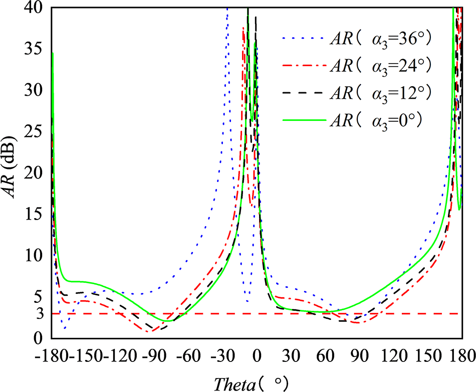
To obtain a smaller axis ratio, four adjustment branches were designed inside the four-arm ring, in Fig. 1(c). These branches are also curved, and their angle to the center of the circle is α 3. When α 3 = 0°, it means that no adjustment branch is loaded. As shown in Fig. 5, with the increase of α 3, the AR at 2.45 GHz of the antenna gradually becomes better. However, when α 3 is greater than 24°, the AR deteriorates rapidly.
Impact of parameter α 3 on AR at 2.45 GHz.

Angle of button-like patch
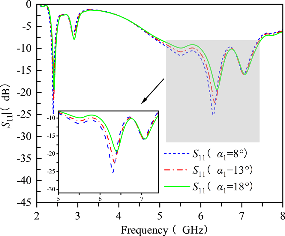
As shown in Fig. 1(b), the rigid button radiator is a circular patch that is hollowed out, and parameter α 1 indicates the angle of the patch. Figure 6 shows that with the angle α 1 growing larger, the upper resonant band gradually moves to the left, while the low-frequency resonant point changes slightly. That is to say, the button-like patch antenna operates at around 5.8 GHz, and the parameter α 1 can be used to fine-tune the position of the resonant zero point. The detailed parameters of the antenna were finally obtained and presented in Table 2.
Influence of parameter α 1 on |S 11|.

Antenna dimensions (unit: mm and deg.)

Experimental verification
The test piece of the antenna is fabricated and measured. The photograph of the antenna is shown in Fig. 7. The flexible conductor is made of conductive fabric, which is made of a mixture of wire and cloth. The back of the fabric is coated with glue. In addition, the flexible substrate is made of wool felt. To make the antenna, conductive fabric is glued to both sides of the wool felt, and then a laser is used to carve out the radiator and the ground. Finally, as shown in the back view of the antenna, a metal platform made of aluminum is glued to the ground. This is not only easy to install the coaxial connector but also easy to weld the shorted pin to ground.
Photograph of fabricated antenna.

Figure 8(a) shows measured reflection coefficients of the antenna in different scene. The lower band bandwidth in the free space is from 2.35 to 2.47 GHz (5%), which is basically consistent with the simulation results. In upper band, the measured bandwidth ranges from 5.06 to 7.23 GHz (35%). Compared with the simulation results, the band is shifted to the high frequency about 400 MHz. Due to the large ground plane designed with conductive fabric, and the 8–10 mm spacing between the antenna and the skin, the human body has little influence on the impedance matching of the antenna. As shown in Fig. 8(b), the proposed antenna generates omnidirectional circularly polarized radiation in the lower band, and its average gain is about 0.15 dBi. The AR is about 1.7 dB at 2.45 GHz, and the minimum AR is 0.15 dB at 2.3 GHz. A linearly polarized broadside radiation pattern is generated by the antenna in upper band. The gain is measured to be about 5.95dB at 5.8 GHz, which is 0.6 dB less than the simulation result.
Measured results of the proposed antenna, (a) |S 11|, (b) AR and gains.

In Fig. 9, the measured radiation patterns of the antenna are shown. The omnidirectional radiation pattern is generated at 2.45 GHz. The measured peak gain in the azimuth plane is 0.15 dBi, and the gain ripple in the azimuth plane is only 1.8 dB. Besides, the pattern in the xoy-plane is somewhat asymmetrical, possibly due to the influence of the short-circuit pin. At the 5.8 GHz, the measured gain at the broadside is 5.95 dBi. The cross-polarization level is below −24 dB in the direction of maximum radiation. In addition, the beam widths of the antenna are 57.8° and 70.5° in the xoz and yoz planes, respectively.
Measured far-field patterns in free space at (a) 2.45, and (b) 5.8 GHz.

Last but not least, the Gustav voxel model in the CST Microwave Suite is used to calculate the 1-g tissue with the power of 0.1 W into the port. The results show that the maximum SAR value is 0.128 W/kg at 2.45 GHz and that at 5.8 GHz is 0.055 W/kg, both of which are far below the standard of the United States (1.6 W/kg) and the European Union (2.0 W/kg).
Conclusion
In this letter, a compact wearable antenna was proposed for WBAN application. The rigid button-like radiator of the antenna can generate a directional broadside radiation pattern, which is suitable for the off-body mode of WBAN. The flexible fabric radiator excites omnidirectional circularly polarized pattern and is suitable for on-body mode. The bandwidth for two bands are 5% and 35%, and the gain is measured to be 0.15 and 5.95 dBi, respectively. Furthermore, the maximum SAR values are far below the standard of the United States and the European Union.
Funding statement
This work was supported in part by the Key Research and Development Program of Shaanxi under Grant 2024GX-ZDCYL-01-29 and in part by the Science and Technology Project of Xi’an City under Grant 24KPZT0010.
Competing interests
The authors report no conflict of interest.

Yuhui Ren received the B.S. degree in communication engineering from the China University of Geosciences, Wuhan, China, in 2003, the M.S. degree in signal and information processing from Northwest University, Xi’an, China, in 2010, and the Ph.D. degree in electromagnetic wave and microwave technology from Northwestern Poly technical University, Xi’an, in 2017. He is currently an associate professor with the School of Information Science and Technology, Northwest University. His research interests include antenna array designs, metamaterials, and UWB antennas.

Jiaxin Lv received a master’s degree in electronic and communication engineering from Northwestern University in 2024. Her main research interests are direction is wearable antennas applied to wireless body area networks.

Kemeng Yan received her bachelor’s degree in materials science from Shaanxi University of Science and Technology in 2021. She has been a Master’s student at the School of Information Science and Technology, Northwest University since 2023. She conducts her research under the supervision of Associate Professor Yuhui Ren. Her current research interests include the design and development of metamaterial-based microwave absorbers.

Bai Wei was born in November 1988. Graduated from Shaanxi Aeronautical Vocational and Technical College with a major in Computer Communication in 2010. In 2011, I worked at Xi ‘an Hengda Microwave Technology Development Co., LTD., engaged in antenna design and testing.

Cui Feng, born in February 1979, is a senior engineer and chief engineer at Xi ‘an Hengda Microwave Technology Development Co., LTD. Mainly engaged in microwave, radar, communication equipment, antenna design and technical management work. Since 2003, I have participated in or led dozens of major scientific research projects.

Ke Li received the B.S. degree in electronic information engineering and the Ph.D. degree in electromagnetic wave and microwave technology from Xidian University, Xi’an, China, in 2011 and 2016, respectively. She is currently an associate professor with the School of Information Science and Technology, Northwest University, Xi’an. Her research interests include multiband antenna design, reconfigurable antennas, and metamaterials.

Han-Dong Wu was born in Jiangsu, China, in 1952. He received the B.S. degree in microwave technology from the Beijing Institute of Technology, Beijing, China, in 1976. From 1977 to 1992, he was an Engineer with the North Electronics Research Institute, Norinco Group. He founded Xi’an Hengda Microwave Technology Development Company Ltd., where he has been a Chief Engineer since 1993. He has authored over 80 articles. His research interests include microwave measurements, phased-array antenna design, and microwave circuit designs.

Fu-Wei Wang received the B.S. degree in electronic information engineering and the Ph.D. degree in electromagnetic wave and microwave technology from Xidian University, Xi’an, China, in 2009 and 2014, respectively. He is currently a lecturer with the School of Information Science and Technology, Northwest University, Xi’an. His research interests include antenna scattering, antenna RCS reduction, and metamaterials.