I. INTRODUCTION
During the last 10 years, the rapid prototyping and manufacturing techniques have received more and more interest from the industry. These techniques allow shaping of three-dimensional (3D) technical parts from a 3D-computer aided design (3D-CAD) representation. As a noticeable consequence, these techniques lead to a dramatic reduction of the processing time to produce a functional prototype. The cost effectiveness of these prototyping processes is considerably enhanced. The most popular solid freeform fabrication processes are fused deposition modeling, laminated object manufacturing, stereolithography, and selective laser sintering/melting (SLS/SLM). Reference Bourell, Marcus, Barlow and Beaman1,Reference Kruth, Levy, Klocke and Childs2 Nowadays, SLM is considered as an almost mature technique to process metals and polymers. Reference Pawlowski3 Processing of ceramics with this technology is unfortunately more complicated due to their intrinsic brittleness, low thermal shock resistance, and high refractoriness. Nevertheless, several researches are focused on the fabrication of ceramic coatings or monolithic parts by laser processes. Reference Bourell, Marcus, Barlow and Beaman1–Reference Wu, Du, Choy and Hench9 One of the primary challenges is to perform SLS or melting in two dimensions (on coatings or powder beds) which is a prerequisite to build up 3D ceramic parts. The secondary challenge is to fabricate 3D parts which may compete with those produced by more conventional techniques (mostly in terms of strength, toughness, dimensional accuracy, and roughness).
The objective of this article concerns the additive manufacturing of dense ceramic parts by selective laser process. The results reported here are related to selective laser treatments performed on alumina powder beds with the aim to find out the most suitable parameters to achieve melting or sintering. Tests were carried out with a fiber laser emitting at 1070 nm, a wave length typical for most of SLM machines and for which alumina is almost nonabsorbent. Even if alumina becomes highly absorbent in the far-infrared (IR) region, the larger spot size of sources operating in this region (ex: at least 80 µm for a CO2 laser against 30 µm for a fiber laser) is considered as unsuitable to ensure dimensional accuracy of parts and/or for the fabrication of small items. To compensate the poor absorptivity of alumina at 1070 nm, an additive was mixed with the ceramic powder to improve the laser beam/ceramic coupling. The influence of several laser parameters such as energy density, power, hatch spacing was assessed through a parametric study. The most relevant SLM parameters to obtain dense microstructures were determined.
II. EXPERIMENTAL
A. Principle of SLM of materials
SLM is a layer-by-layer manufacturing process which typically comprises five steps:
-
(i) A 3D-CAD file of an object is sliced in two-dimensional (2D)-elements corresponding to laser scan vector data for each layer.
-
(ii) A layer of powder (with a controlled thickness) is deposited on the building platform.
-
(iii) The powder bed is sintered or molten selectively (thanks to the scan vectors of 2D-element) by the laser beam deflected by a galvanometer scanner.
-
(iv) The building platform is lowered by a height corresponding to one layer thickness.
-
(v) Steps (ii) to (iv) are repeated until completion of the object building up.
-
(vi) The powder not irradiated by laser is brushed away from the objet and can be reused later to build up another part.
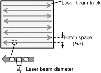
The SLM machine used in this study was a Renishaw-AM125 (Renishaw, Wooton-under-Edge, Gloucestershire, UK). It uses a high-power (P max = 200 W (cw)) fiber laser (λ = 1070 nm) and comprises a building chamber of 125 × 125 × 100 mm3 size, which is swept by argon to maintain an inert gas environment. The main parameters for fine-tuning processing are illustrated in Fig. 1 and listed hereafter:
-
(a) Laser power (P)
-
(b) Laser beam diameter (ɸ z )
-
(c) Exposure time for each point (t)
-
(d) Hatch space (HS): defined as the distance between two consecutive parallel laser tracks
-
(e) Point distance (pd): defined as the distance between two consecutives laser spot area irradiated
Laser key parameters.

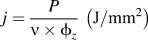
In the literature, Reference Yang, Bai, Xie, Kuang, Liu, Zhuang, Tong and Liang7,Reference Jasim, Rawlings and West10,Reference Tian, Günster, Melcher, Li and Heinrich11 laser treatments are evaluated by using energy density applied on the material as defined in Eqs. (1) and (2).
 $$j = {P \over {{\rm{\nu }} \times \phi _z }}\;\left( {{\rm{J}}/{\rm{mm}}^2 } \right)$$
where
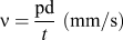 $${\rm{\nu }} = {{{\rm{pd}}} \over t}\;\left( {{\rm{mm}}/{\rm{s}}} \right)$$
where ɸ z is the diameter of the laser beam (69 µm in the present work) and v the laser scan speed.
B. Materials and sample preparation
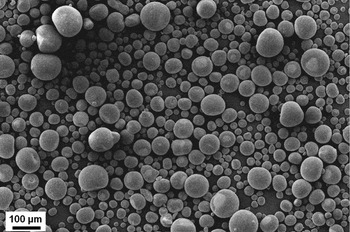
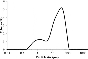
The alumina used in present work is P172 SB (99.7% purity) from Alcan. This powder was dispersed in water using a dispersing agent (Dolapix CE64 – Zschimmer & Schwarz, Lahnstein, Allemagne) and alumina balls media to reach a mean particle size of 0.4 µm (measured by laser scattering on a Malvern Mastersizer 2000, Malvern, UK). The slurry was then split into two batches. The first batch was spray-dried to get a granulated powder which was considered as the reference powder. A graphite-based colloidal suspension, called hereafter absorption additive, was added in the second batch. After subsequent milling, this slurry was spray-dried as previously. Both powders were sieved to 106 µm and the spherical shape of the spray-dried granules was confirmed (Fig. 2 and Fig. 3).
Example of spherical alumina particles obtained after spray drying (SEM image on a JEOL JSM-5900LV).

Typical particle size distribution of the spray-dried granules after sieving at 106 µm.

C. Laser processing
A laser marking machine (TruMark station 5000 new – TRUMPF, TRUMPF laser- und Systemtechnik GmbH, Ditzingen, Gremany) equipped with a Nd–YVO4 source emitting at a wave length of 1064 nm with a maximum power = 20 W (cw) was used to perform preliminary laser tests on pellets die-pressed at 45 MPa. These tests aimed at evaluating the effect of the absorption additive on the powder/laser optical coupling. The influence of each parameter listed in Sec. II. A was assessed.
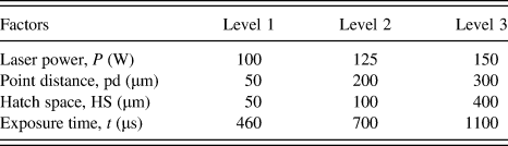
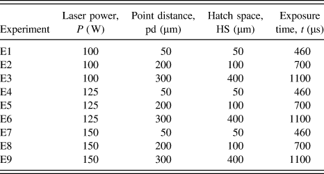
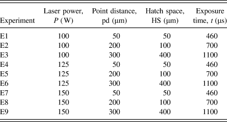
The number of combinations for SLM processing prohibits the evaluation of each set of parameters. To reduce the experiment time and to find out the most relevant parameters for, a fractional factorial design of experiment was considered. The Taguchi's method was used to extract a representative subset of the full factorial experimental array with 81 combinations available. By applying Taguchi's method with three levels for each of the laser key parameters (see Table I), nine representative experiments were extracted. These levels were determined from SLM screening tests.
Levels for factors in SLM process.
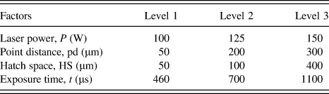
The selected subset array of nine representative experiments is presented in Table II.
Experimental scheme for the SLM process.
D. Samples characterization
Microstructures of ceramic bodies were observed by scanning electronic microscopy (SEM; JEOL JSM-5900LV, JEOL, Tokyo, Japan). Reflectance measurements were performed using an ultraviolet-visible light-near infrared spectrometer (UV/VIS/NIR; Perkin Elmer lambda 750, Waltham, MA). Crystal phase identification was performed using an x-ray diffractometer (XRD; Philips PW1729, Philips, Holland), with Cu Kα radiation. Dilatometric analysis was performed on a Setaram TMA92-16/18 (Setaram Instrumentation, Caluire, France). The density of SLM-processed parts was measured using Archimedes' method in water.
III. RESULTS AND DISCUSSION
A. Selective laser treatments of alumina without absorption additive
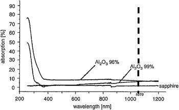
A broad range of laser parameters was considered for sintering/melting of pellets top surfaces with the Nd:YVO4 laser. Unfortunately, the irradiated surfaces did not reach a temperature high enough to allow material diffusion, grains bonding, and subsequent sintering or melting. As reported in the literature, the energy conversion of laser light into thermal energy is a function of the parameters reminded in Sec. II. A. However at a power of 20 W and considering the very poor coupling of alumina and laser at 1064 nm (alumina absorbs less than 10% of laser energy for wave length around 1000 nm as shown in Fig. 4 (Refs. Reference Hellrung, Yeh, Depiereux, Gillner and Poprawe12,Reference Pham, Dimov and Petkov13)), the energy density was clearly not enough to reach conditions of sintering/melting. Furthermore, the laser/matter interaction is not only a function of the laser wave length but also of the grain size and porosity of the pellets: although some fraction of the incident laser beam is reflected, a nonnegligible part of the remaining energy is absorbed by the material through multiple reflections on a certain depth of the pellets. Reference Shao, Lin and Zhou14 Usually, this effect improves the effective amount of absorbed energy. Reference Pham, Dimov and Petkov13–Reference Deckers, Shazad, Vleuels and Kruth15 Unfortunately, the low absorbance of alumina in the near-IR region was obviously not compensated by this mechanism in our preliminary experiments.
Comparison of wave length absorption of alumina adapted from Hellrung et al. Reference Hellrung, Yeh, Depiereux, Gillner and Poprawe12

Complementary tests were therefore performed at much higher laser powers on the SLM machine (up to 200 W) on single layers of powder. However, the results did not show any difference with those obtained on the marking machine at 20 W.
B. Selective laser treatments of alumina with absorption additive
As said previously, colloidal graphite was added within the ceramic granules to increase the optical coupling between the laser beam and alumina. Adding graphite presents two advantages: it exhibits a very high absorptivity at 1070 nm (>0.9) and it does not react with alumina, even at high temperature. Hence, there is no risk of forming new undesirable phases during the laser treatments. The effect of graphite addition on the alumina absorptivity was determined by spectrometry. The reflectance (R) of the material was measured on 5-mm-thick green pellets. Then the absorbance (A), defined as the ratio of absorbed radiation to the incident radiation, was calculated according the usual formula given in Eq. (3). Reference Tolochko, Laoui, Khlopkov, Mozzharov, Titov and Ignatiev16
 $$A = 1 - R - T$$
where T is the transmittance. In the present study, T was considered equal to zero considering the thickness of the pellets (whatever the amount of additive).
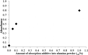
The absorbance for pure alumina is calculated in accordance with Hellrung et al. Reference Hellrung, Yeh, Depiereux, Gillner and Poprawe12 Figure 5 shows the absorbance evolution for increasing amounts of absorption additive into alumina. At 1 vol%, the mixed powder exhibits an absorbance around 0.8.
Change of absorbance of alumina with absorption additive ratio.

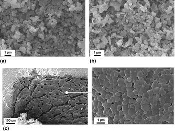
Comparison of irradiated areas in pellets containing or not the additive reveals significant changes (Fig. 6). Consolidated microstructures with grains around 1 µm are visible for pellets containing 0.1 vol% of graphite. The grains are bonded to each other and form bigger particles with a spherical morphology and sintered necks. Unfortunately, the irradiated areas are significantly damaged with cracks and porosity. The presence of cracks can be explained by shrinkage occurring during sintering, thermal shocks, and/or thermal stresses induced by a heterogeneous sintering. Some pores are also noticed and are probably related to the graphite burning off during the laser treatment. Another possibility to explain these defects, according to the study of Deckers et al. Reference Deckers, Shazad, Vleuels and Kruth15 is a local overheating of alumina leading to a subsequent boiling. Despite these defects, it is clear that the addition of graphite in alumina enhances the optical coupling and favors consolidation during the laser treatment.
SEM micrographs of (a) alumina green body without laser treatment, (b) laser treated area of top surface of alumina green body, and (c) laser treated area of alumina green body containing the absorption additive.

C. Density and microstructure
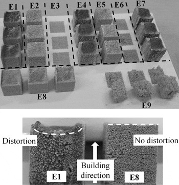
SLM cubes (10 × 10 × 10 mm3) were manufactured according to the design of experiment and starting from the alumina powder containing 0.1 vol% graphite. A total of ten cubes for each experiment were fabricated. Figure 7 shows an example of results.
Test specimens manufactured by SLM for density measurement.

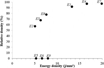
All experiments from Table II, have not led to dense bulk cubes from the powder bed (Fig. 7). The powder bed was not densified for experiments E3 and E6. For experiment E9, the specimen exhibited a too weak mechanical resistance to be manipulated. Therefore, for experiments E3, E6, and E9, the densification levels of powder beds are considered equal to 0%.
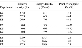
The highest relative densities were obtained with experiments E4, E7, and E1 with 97.5, 97.3, and 92.9%, respectively (Table III). But slight shifts of geometry following the Z axis compared to the 3D-CAD model were observed for these experiments. In these cases, the temperature of the powder bed seems to have reached the alumina melting point, inducing menisci in irradiated areas. Distortions observed along the Z axis could be explained by the freezing of menisci, due to the rapid cooling. According to this explanation, the geometrical distortion shown in Fig. 7 (E1) would result from the addition of each slight layer deformation. Contrarily, a good geometric accuracy following X, Y, and Z axis, was observed with experiments E8, E5, and E2 leading to lower densities (76.9, 67.3, and 57.2%, respectively).
Relative densities obtained by applying the experimental scheme of Table II.

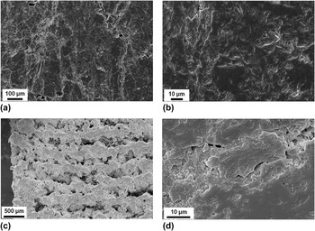
Figure 8 shows SEM micrographs of polished cross sections of specimens obtained from experiments E4 and E8. SEM micrographs of experiment E8 [Figs. 8(c) and 8(d)] show porosity, cracks, and large periodic defects along the building direction. It is believed that some visible pores are the consequence of stacking defects in the powder bed. But large periodic defects likely results from a lack of cohesion between two consecutive layers. In this case, the energy density is probably no sufficient to weld consecutive layers, contrary to results obtained with experiment E4 [Figs. 8(a) and 8(b)] leading to a higher density and where cracks and pores are the major defects. The energy density applied for this experiment (16.6 J/mm²) seems to be suitable to avoid the largest defects, but not the smallest ones, like pores.
SEM micrographs of (a and b) experiment E4 and (c and d) experiment E8.

D. Influence of laser parameters on powder bed densification
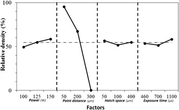
The influence of each laser parameters on the density is reported in Fig. 9. Among the four factors investigated, point distance (pd) has the strongest influence, hatch space (HS) and exposure time (t) have a similar effect on the evolution of density. The change of power (P) leads to a surprisingly insignificant effect on densification of powder bed compared to point distance. Considering Fig. 9, point distance should be chosen as low as possible, i.e., around 50 µm according to the present study.
Average effect of laser parameters upon powder bed densification.

To understand how densification is affected by the laser treatment, it is useful to plot the relative density as a function of laser energy density (j). Figure 10 shows that globally, the densification of powder bed increases with laser energy density. But for experiments E3, E6, and E9 energy densities are similar to those of E2, E5, and E8 whereas densification rate is equal to zero. It is clear that the laser energy density is not sufficient to explain densification. Points overlapping [Eq. (4)] seems to be more relevant. If Ov > 0, there is an overlap of successive laser spots. And for Ov < 0, there is no contact between successive spots inside laser tracks.
 $${\rm{Point}}\;{\rm{overlapping:}}\;{\rm{Ov}} = (1 - ({{{\rm{HS}}} \mathord{\left/ {\vphantom {{{\rm{HS}}} {{\phi _z}}}} \right. \kern-\nulldelimiterspace} {{\phi _z}}}))$$
Change of parts relative density as a function of laser energy density.

As previously reported in the literature, the laser track overlapping exerts a significant influence on microstructures and geometrical feature of 3D parts. Reference Su and Yang17
For experiments E2, E5, and E8, the applied energy densities are 5.1, 6.3, and 7.6 J/mm², respectively, with Ov = −44% (a negative value means that no overlapping occurs). For experiments E3, E6, and E9, the energy densities are 5.3, 6.6, and 7.9 J/mm², respectively, with Ov = −477%. Finally, for experiments E1, E4, and E7, the energy densities are 13.3, 16.6, and 19.9 J/mm², respectively, with Ov = 28% (Table III). In the latest case only there is an overlap between consecutive laser spots contrary to the two other cases. The absence of powder bed densification can be explained by a too large distance between successive irradiated zones which do not lead to a single continuous track of densified material.
E. Influence of slice thickness on microstructure
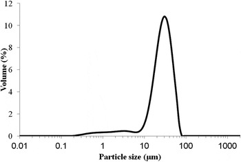
In an attempt to increase further the density and quality of SLM parts, the influence of the layer thickness was studied. The initial layer thickness of 100 µm was reduced to 50 µm by sieving the alumina granules at 50 µm. Figure 11 shows the particle size distribution of the granules used to build items with a layer thickness of 50 µm. Figure 12 shows the change of microstructures obtained by applying parameters of experiment E8. By decreasing the layer thickness from 100 to 50 µm, an increase of density was observed from 76.9 to 85.1%, respectively. SEM micrograph of the parts cross section [Fig. 12(a)] shows a net improvement of the microstructure with smaller pores size [Fig. 12(b)]. This change may be explained by a more homogeneous and efficient melting of the powder bed allowing a better welding between two consecutive layers.
Particle size distribution of the spray-dried granules after sieving at 50 µm.

Influence of layer thickness upon SLM microstructures (a) 100 µm slice, (b) 50-µm slice, and (c) 50 µm slice with postthermal treatment at 1550 °C/2 h.

A suitable setting of laser parameters and a decrease of layer thickness clearly improve microstructures and the relative density of parts. Unfortunately, cracks and heterogeneities are still noticed. It is expected that the amount of defects may be decreased by considering some improvements of powder bed density. This could be achieved either through the use of more suitable powders and/or by considering specific devices to precompact the powder bed before laser irradiation. This clearly requires further technological developments. An alternative approach would be to use slurries instead of powder. This approach also known as the layer-wise slurry deposition leads to improved green density and is described by Tian et al. Reference Tian, Günster, Melcher, Li and Heinrich11,Reference Tian, Mühler, Gomez, Günster and Heinrich18 However, this wet process required additional steps compared to our dry SLM process.
F. Influence of a thermal posttreatment
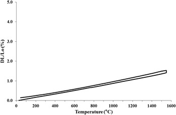
To increase the quality of parts, a thermal posttreatment was applied. Cubes manufactured by SLM with a 50 µm slice thickness were heat treated at 1550 °C for two hours. This temperature is usually considered to obtain fully dense objects with alumina P172 SB. Prior heat-treatment the density was 85.1%. Exactly the same value was obtained after postprocessing. Figure 12(c) shows the microstructure after posttreatment. Numerous cracks occurring perpendicular to building direction can now be observed. They may originate from a release of residual stresses in the structure during the thermal treatment, or an evacuation of gas resulting from the degradation of remnants of absorption additive. Dilatometric analysis of specimen before postthermal treatment shows no significant shrinkage (Fig. 13). SEM micrograph [Fig. 12(b)] exhibits clearly a molten structure suggesting that the temperature reached during SLM is over the melting temperature of alumina (T m = 2070 °C). According to the study of Bertrand et al., Reference Bertrand, Bayle, Combe, Goeuriot and Smurov19 the density cannot be increased by conventional postthermal treatment which is much lower than the shaping temperature. For a temperature lower than that achieved by SLM, internal rearrangement of matter is locked.
Dilatometric analysis of specimen manufactured by SLM with laser parameter of experiment E8 and slice thickness of 50 µm.

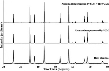
XRD analysis of SLM parts (Fig. 14) shows that the structures are well crystallized (despite melting) and that no change of the original crystalline structure of alumina occurs. Moreover, there is no glassy phase nor any secondary phase detected as a consequence of graphite addition.
Comparison of XRD patterns of raw alumina powder, SLM-treated alumina, and posttreated alumina parts at 1550 °C/2 h.

G. 3D complex shapes for demonstration purposes
By tuning laser parameters from the design of experiments, specimens with relative density of over 90% were manufactured without geometric deformation. Table IV shows that the level of density can be kept constant by decreasing the absorption additive ratio from 1.00 to 0.05 vol% for a same set of laser parameters.
Absence of effect of graphite amount addition (in the range 0.05–1 vol%) on the part density. (Laser parameters: P = 150 W; pd = 200 µm; HS = 50 µm; t = 700 µs).

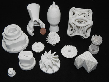
For demonstrating purposes, 3D complex shapes have been manufactured from alumina powder containing 0.05 vol% absorption additive (Fig. 15). The relative density of these large objects was confirmed around 90% similar to that obtained on small cubes.
Pure alumina parts processed by SLM.

IV. CONCLUSIONS
This work highlights the benefit of incorporating an absorption additive to consolidate alumina powder beds and manufacture 3D parts using a near-IR laser. The main advantage of the present strategy relies on the fact that there is no residue of the additive remaining after SLM processing. Our approach is suitable to consolidate any ceramic materials exhibiting a low absorbance in the near infrared wave length where most SLM equipments operate.
Our results show that not all laser parameters have similar influence on the powder beds densification. The most important parameters are the point distance parameter, the laser energy density, and the point overlapping between consecutive laser spots.
The possibility to manufacture alumina parts by SLM has been demonstrated without requiring a glassy phase or a low melting point phase acting as a binder for the ceramic grains. Nevertheless, even if the relative densities are exceeding 90%, microstructures are still damaged. This remains an open issue of this work. It may probably be overcome by a better temperature control of powder bed during SLM. The assessment of the mechanical properties of the parts is left for future works.
ACKNOWLEDGMENT
The European Regional Development Fund (ERDF) and Wallonia, are gratefully acknowledged for their financial support of this research project (Revêtements Fonctionnels – LASESURF – ECV12020010884F-830033) in the frame of the “Convergence programme”.