Introduction
Dual-polarized antennas have attracted much interest for several decades as employed multiple-input-multiple-output (MIMO) antennas in the field of wireless communications [Reference Zhu, Chen and Yang1, Reference Bellary, Kandasamy and Rao2], instead of two separated antennas with single polarization for capacity extension. For 360° coverage, omni-directional dual-polarized antennas are commonly applied. Thus, a series of dual-polarized omni-directional antennas have been reported [Reference Wen, Xu and Dong3–Reference Zhang, Liu, Yin and Li7].
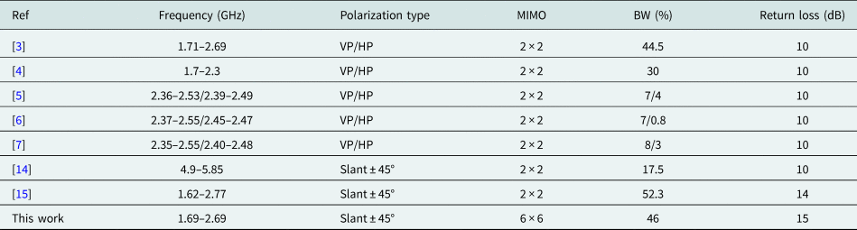
In [Reference Wen, Xu and Dong3], a dual-polarized omni-directional antenna with horizontal polarization (HP) and vertical polarization (VP) is achieved by eight stepped-impedance slots cut on the printed circuit board with a shorted cylindrical cavity. In [Reference Fan, Liu, Liu and Li4], a broadband dual-polarized omni-directional antenna with HP and VP is realized by four pairs of orthogonal dipoles printed on a cylinder-shaped barrel. In [Reference Zhang and Li5], a scalable dual-polarized antenna using the open-ended cavity for HP and a slot-dipole hybrid structure for VP is designed to achieve the omnidirectional radiation. In [Reference Zhang, Li, Zhang, Zhang and Feng6], a probe-fed cavity for HP radiation and a microstrip-fed slot for VP are adopted to realize the omnidirectional radiation. In [Reference Zhang, Liu, Yin and Li7], an omnidirectional dual-polarized antenna is introduced by two identical half-wavelength slots etched onto the cavity sidewalls symmetrically and VP achieved by another horizontal slot. However, the polarizations of these antennas are HP and VP, which have worse symmetrical propagation properties than slant ±45° dual polarizations used widely [Reference Lindmark and Nilsson8–Reference Jia, Liao and Xue13]. Also the operation bandwidth is narrow that is from 3% to 44.5%, and the construction is offering 2 × 2 MIMO only. So these antennas are very challenging to be applied for the capacity enhancement in modern communication systems. To overcome the above-mentioned issues, wideband slant ±45° dual-polarized omnidirectional antennas are proposed in [Reference Xun and Ge14, Reference Ye, Cao, Zhang, Gao and Xue15], in which several panel antenna arrays are configured in a cylinder fed by a power divider for a 360 coverage. Then these antennas only serve the application for 2 × 2 MIMO as well. For enhancement wireless network capacity in the field, they need to be mounting more antennas. In fact, for practical application of wireless network capacity enhancement of small cell coverage scenario, it requires to be performed in the limited size and cost effective [Reference Shen, Jamali and Wu16–Reference Bantavis, Kolitsidas, Empliouk, Le Roy, Jonsson and Kyriacou18].
In this paper, a broadband slant ±45° dual-polarized omni-directional antenna is presented working at operating frequency band of 1.69–2.69 GHz. The proposed antenna consists of two identical Butler matrix-based azimuth beamforming networks (ABFN), three elevation beamforming networks (EBFN), and three-panel broadband cross-dipole elements. Due to the three-panel architecture, in which each panel is pointing to −120°, 0°, +120°, respectively, the 360° omni-directional coverage can be realized by all three beam inputs with −120°/0°/+120° phase increments. The 6 × 6 MIMO is formed by the compact broadband 3 × 3 Butler matrix constructed as ABFN.
Analysis and design
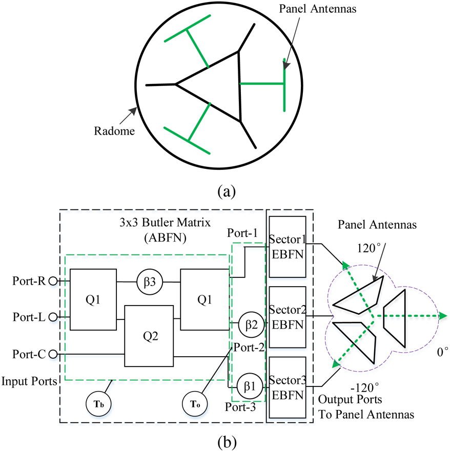
Figure 1(a) shows the cross-section of proposed omni-directional antenna, in which only three panels of slant ±45° dual-polarized subarrays are used. As shown in Fig. 1(b), the proposed omni-directional antenna comprises three main parts: ABFN, EBFN, and dual-polarized dipole elements. For simplicity, only one polarization architecture is shown.
Cross-section of proposed dual-polarized omni-directional antenna (a) and block diagram (b).

Broadband single-layered 3 × 3 Butler matrix (ABFN)
Figure 1(b) shows a 3 × 3 Butler matrix ABFN with three inputs (port-C, port-L, and port-R) and three outputs (port-1, port-2, and port-3), in which there are two quadrature hybrids Q 1, one quadrature hybrid Q 2, and three fixed phase shifters β 1, β 2, and β 3. As we know, the ideal quadrature hybrid couplers can be expressed by an orthogonal transmission matrix Q through the coupling coefficient of the quadrature hybrid. The phase difference between two output ports for any input is 90° due to the orthogonal property of the quadrature hybrid.
Tb is the transmission block of Q 1 and Q 2 with 90° phase shifter β 3, and To is the transmission block of two phase shifters β 1 and β 2 at outputs (i.e. β 1 = 180° and β 2 = 90°). For Q 1 and Q 2, their corresponding coupling coefficients a are $1/\sqrt 2$ and $1/\sqrt 3$
 , respectively. Giving the value of quadrature hybrid Q 1, Q 2, β 1, β 2, and β 3, the transmission block T 3×3 can be expressed as following:

For depiction correlations between amplitudes and phases, transmission block T 3×3 in (1) could be represented by Euler's formula as following:

Based on (2), the phase increment for the C/L/R ports of 3 × 3 Butler matrix are 0°, +120° (2π/3), and −120° (−2π/3), respectively, and signals at four outputs are ideally equal in amplitude of 4.77 dB.
To achieve the wide bandwidth and reduce the size of the quadrature hybrid, a cascaded three-section branch line coupler (BLC) with three-pair coupled line is adopted [Reference Wu and Shen19, Reference Wu and Shen20]. The initial impedance of quarter-wavelength branch lines is given by Z 1 = 54 Ω, Z 2 = 58 Ω, Z 3 = Z 4 = 143 Ω and the phase of quarter-wavelength is θ 1 = θ 2 = θ 3 = θ 4 = 90° [Reference Chun and Hong21]. In order to solve the problem of PCB manufacturing difficulty and high impedance affection caused by manufacturing tolerance, a single-layered layout with defected ground structure (DGS) [Reference Lim, Kim, Ahn, Jeong and Nam22] is conducted into the BLC design. DGS structures are used to give the increased equivalent inductance (L) and produce transmission lines with high impedance. The characteristic impedance of high impedance transmission line can be derived by $Zo = \sqrt {L/C}$ .
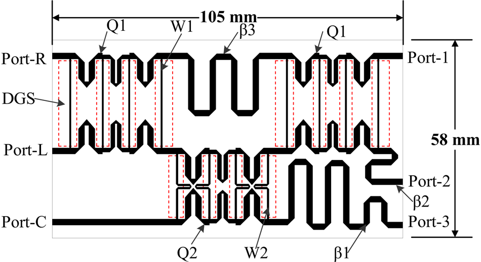
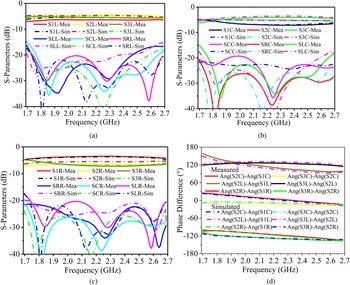
The proposed 3 × 3 Butler ABFN is designed based on the Rogers RO4534 substrate with a relative dielectric constant of 3.50 and a thickness of 0.82 mm as shown in Fig. 2. It is simulated by Mentor Graphics IE3D. The width of 50 Ω microstrip line is 1.80 mm, and the high impedance microstrip line's width of 3 dB and 4.77 dB BLC is 0.5 mm (W 1) and 0.6 mm (W 2), respectively. In Figs 3(a)–3(c), the simulated amplitude distribution values at full frequency band of 1.69–2.69 GHz are −5.3 ± 1.5 dB when port-R is excited; −5.3 ± 1.5 dB when port-L is excited; and −5.3 ± 0.7 dB when port-C is excited. The simulated worst-case return loss is 15 dB, and the simulated worst-case isolation among port-C, port-L, and port-R are 17, 23, and 17 dB, respectively. In Fig. 3(d), the averaging simulated phase difference between two neighboring ports at the center frequency of 2.19 GHz is −122° of port-R, +118° of port-L, and −2° of port-C.
PCB layout of proposed BLC.

Simulated and measured response of proposed 3 × 3 Butler network (ABFN): (a) port-L excited. (b) Port-C excited. (c) Port-R excited. (d) Transmission phase difference.

Dual-polarized radiation element configuration
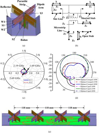
To achieve wide bandwidth and ±45° polarizations, the antenna radiation element comprises two cross-dipole arms, four parasitic strips, two perpendicular baluns, and a square bent ground reflector. Compared with the traditional dipole antenna element, a pair of parasitic strips with width W 1 and gap S 3 are added to extend the frequency bandwidth and improve the radiation performance [Reference Tao, Feng and Liu23, Reference Tao, Feng, Vandenbosch and Volskiy24]. By adjusting the lengths, widths, and gaps between the dipole arms and parasitic strips (W 1, W 2, S 1, S 2, S 3, and their corresponding lengths), the operating frequency band of the antenna can be adjusted flexibly. For impedance matching, two PCB baluns are designed for broadband application [Reference Ye, Zhang, Gao and Xue25–Reference Li, Wu, Pan, Lim, Laskar and Tentzeris28]. The configuration of the balun is displayed in Fig. 4(a) and its equivalent circuit is shown in Fig. 4(b). The matching steps are listed as following:

where Zd is the input impedance of the printed dipole without the integrated balun; Zs, βs, and lt are the characteristic impedance, phase constant, and the length of the slot line; ls is the length of the shorted stub; r is the impedance transformer coefficient; Zc, βc, and lc are the characteristic impedance, phase constant, and the length of open stub, respectively. Zd could be obtained by giving the excitation to the input port of dipole. According to the impedance matching theory, Z 3 can be deduced from (4).

where Zk is defined by the input port impedance with 50 Ω. For simplifying the calculation, the turn ratio of transformer, r could be set to be 1:1 initially. The initial dimensions of the balun can be estimated through above equations and the microstrip line formula. The cross-dipole is printed on the top of a substrate of dielectric constant 3.50 and thickness 0.82 mm. The height of its substrate is selected as 0.238λ 0 for high gain. By applying parameter optimization in Ansys HFSS, the wideband dual polarization dipole element with W 1 = W 2 = 10 mm, S 1 = S 2 = 2 mm, and S 3 = 9 mm is obtained. The size of the proposed antenna element is 81.0 × 49.0 mm2. The simulated results of proposed dipoles are shown in Figs 4(c)–4(d). The worst VSWR is less than 1.4 at full operating band and horizontal half-power beamwidth varies from 79° to 83°.
Geometry of a printed cross-dipole with adjusted integrated balun (a), equivalent circuit of the proposed printed dipole with adjusted integrated balun (b), simulated input impedance/VSWR of proposed elements (c), simulated radiation pattern of horizontal plane at 1690, 2190, and 2690 MHz (d), geometry of dual-polarized panel antennas fed by EBFN (e).

Dual-polarized panel array fed by EBFN
To realize the dual-polarized omni-directional antenna, a medium gain array with three elevation panels working at the full frequency band of 1.69–2.69 GHz is considered. In each elevation panel shown in Fig. 4(e), there are four broadband antenna elements connected by EBFN with 4° electrical down tilt (EDT). By minimizing the mutual coupling between elements, a 0.86λ o spacing is applied, where λ o is the wavelength in air of the center frequency of 2.19 GHz. The EBFN is designed based on Chebyshev distribution, and the ideal power levels of four antenna elements are −4.77, 0, 0, and −4.77 dB, respectively. The ideal phases of four antenna elements with 4° EDT are 0°, −21.2°, −42.4°, and −63.5°, respectively.
Dual-polarized omni-directional antenna fed by BFNs
Through connecting output ports of ABFN boards to the input ports of EBFN boards with three identical dual-polarized panel arrays formed in a cylinder as shown in Fig. 1(a), the Butler-based dual-polarized omni-directional antenna is achieved. The input signal flows to the each dual-polarized panel through both ABFN and EBFN. There are six ports in which three ports produce +45° (L+/C+/R+) polarized radiation and other three ports produce −45° (L−/C−/R−) polarized radiation. The whole antenna structure is investigated by Ansys HFSS. The simulation results show that, for port-C with 0° phase increment, gain is 9.1–10.7 dBi and the azimuth null is 5.1 dB; for port-L/R with ±120° phase increment, gain is 9.3–10.8 dBi and the azimuth null is 12.5 dB.
Experimental results
For validation, the several antenna samples are fabricated and tested by Keysight ENA E5071C and NSI spherical near-field chamber. Figure 4 shows measured responses of proposed 3 × 3 Butler ABFN: port-L excited (a), port-C excited (b), port-R excited (c), and transmission phase difference (d). The measured phase differences between two neighboring ports at the center frequency of 2.19 GHz are −122° in averaging of port-R, +118° in averaging of port-L, and −3° in averaging of port-C. The worst-case measured return loss is 15 dB, the worst-case isolation among port-C, port-L, and port-R are 15, 20, and 17.5 dB, respectively. The measured transmission amplitudes at full band of 1.69–2.69 GHz are −5.6 ± 1.3 dB when port-L is excited; −5.6 ± 1.5 dB when port-C is excited; and −5.3 ± 1.7 dB when port-R is excited. The measured insertion loss of the proposed Butler matrix is 0.33 dB with port-C excited and 0.44 dB with port-L/R excited.
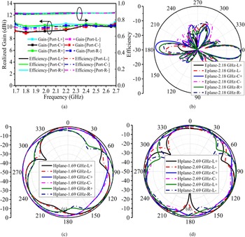
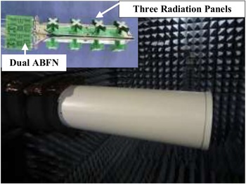
The measured results of the proposed omni-directional antenna are shown in Fig. 5(a), for port-C with 0° phase increment, gain is 8.9–10.5 dBi; for port-L/R with ±120° phase increment, gain is 9.6–10.6 dBi. The measured efficiency for all ports is higher than 87%. Figures 5(b)–5(d) show the measured elevation and azimuth patterns of the proposed 6 × 6 MIMO antenna at 2.18, 1.69, and 2.69 GHz, respectively. The azimuth null is 2.2 dB at port-C and 14.1 dB at port-L/R, respectively. The plots show the beam point at −120°, 0°, and 120° with a full coverage of 360°. Figure 6 shows the proposed omni-directional antenna under test. The dimension of the fabricated omni-directional antenna gives 154 mm in diameter.
(a) The measured realized gain and efficiency of the proposed omni-directional antenna. The measured elevation pattern at 2.18 GHz (b) and azimuth patterns at 1.69 GHz (c), 2.69 GHz (d).

The proposed dual-polarized omni-directional antenna under test.

Table 1 showing the comparison between proposed Butler-based slant ±45° dual-polarized omni-directional antenna and previous works. As it is seen, the proposed antenna has been forming a 6 × 6 MIMO application with wider operation bandwidth.
Comparison with the previous works

Conclusion
In this paper, a design of the Butler-based dual-polarized omni-directional antenna fed by a compact single-layered broadband 3 × 3 Butler matrix network is presented. The proposed antenna has successfully realized 360° coverage. Also comparing with traditional 2 × 2 MIMO omni-directional antenna fed by T-splitter power divider, the proposed antenna has been forming to 6 × 6 MIMO which could be used for network capacity expansion. Furthermore, the proposed single-layered broadband Butler matrix gives more convenience in network layout and PCB manufacturing.
Conflict of interest
None.
 Xiaoqing Wu received the master degree in electronics and communication engineering from the Soochow University, China, in 2016. He is currently pursuing a Ph.D. at the Soochow University, China. His current research interests include beamforming networks, radio frequency circuits, phased array antenna system, multibeam antennas, and the application of wireless communication systems.
 Lin-Ping Shen received his B.Sc. and M.Sc. in electrical engineering from Nanjing University of Science and Technology, Nanjing, China, in 1985 and 1988. He received his Ph.D. in electrical engineering from McMaster University, Hamilton, ON, Canada, in 2004. He is currently as senior antenna design engineer working in Antenna Research Group, Communication Components Antenna Inc (CCAI), Ottawa, Canada. His current research interests include beamforming antennas, high gain array antennas, multibeam antennas, multiband antennas, radio frequency circuits, and the application of wireless communication systems.
 Lijun Zhang received his Ph.D. from Institute of Microelectronics of The Chinese Academy of Sciences, in 2000. Since 2007, he has been a professor with the Soochow University, China. His current research interests include SOC design and methodology, integrated circuits and the application of wireless communication systems.